Henriksen Giraffe Tracer User manual

USER MANUAL
Giraffe Tracer
Document number: M000375
Revision: -12
Release date: 2020-06-12
USER MANUAL
Giraffe Tracer
Rev.: -12
page 2 of 52
M000375
Revision history
Rev. Pages Description Approved by Date
-10 8
19-20
Additional regulator details
Relief valve adjustment details.
RF 2020-02-13
-11 8 - 10
14
23
More details for the hook
attachment process
Additional details for the hook
disconnecting process
Lubrication comment
RF 2020-04-29
-12 32 - 35 BE390983 Backup Release
Harness added, see pos 21
RF 2020-06-12

USER MANUAL
Giraffe Tracer
Rev.: -12
page 3 of 52
M000375
Table of Contents
1INTRODUCTION ..................................................................................5
2ATTENTION! ........................................................................................5
3TECHNICAL DATA ..............................................................................6
3.1 Description .......................................................................................... 6
3.2 Technical specifications ...................................................................... 6
4OPERATION ........................................................................................7
4.1 Before use........................................................................................... 7
4.2 Preparations........................................................................................ 8
4.3 Operation ...........................................................................................13
4.4 After use.............................................................................................16
4.5 Filling the bottle with an external diving bottle (workaround)..............16
5TRANSPORT .....................................................................................18
5.1 On pontoon ........................................................................................18
5.2 Between seat rows.............................................................................19
5.3 On the deck........................................................................................20
6INSPECTION AND MAINTENANCE .................................................21
6.1 User level ...........................................................................................21
6.2 Maintenance personnel level .............................................................24
7PARTS LIST.......................................................................................28
7.1 Inside .................................................................................................28
7.2 Top section ........................................................................................32
7.3 Middle section ....................................................................................36
7.4 Bottom section ...................................................................................40
7.5 Handlebar and hook...........................................................................42
8TOOLS ...............................................................................................44
8.1 Maintenance Kit .................................................................................44
8.2 Repair Kit ...........................................................................................47
9ACCESSORIES..................................................................................48

USER MANUAL
Giraffe Tracer
Rev.: -12
page 4 of 52
M000375
Table of Figures
Figure 1: Bottle connection ................................................................................... 7
Figure 2: Hook rope attached ............................................................................... 8
Figure 3: Hook attached properly ......................................................................... 9
Figure 4: Locking ball ..........................................................................................10
Figure 5: Carabiners connected properly ............................................................11
Figure 6: Secured and unsecured carabiners......................................................12
Figure 7: Preparation...........................................................................................13
Figure 8: Placing the hook...................................................................................13
Figure 9: Releasing the hook...............................................................................14
Figure 10: Retracting the pole .............................................................................15
Figure 11: Filling with an external diving bottle....................................................16
Figure 12: Relief valve removal ...........................................................................21
Figure 13: Relief valve removal ...........................................................................22
Figure 14: Inside parts 1/2...................................................................................28
Figure 15: Inside parts 2/2...................................................................................30
Figure 16: Top section parts 1/2 ..........................................................................32
Figure 17: Top section parts 2/2 ..........................................................................34
Figure 18: Middle section parts 1/2......................................................................36
Figure 19: Middle section parts 2/2......................................................................38
Figure 20: Bottom section parts...........................................................................40
Figure 21: Handlebar and hook ...........................................................................42

USER MANUAL
Giraffe Tracer
Rev.: -12
page 5 of 52
M000375
1 INTRODUCTION
This use- and maintenance manual for this REBS product is prepared by
the manufacturer to provide necessary information about the use and
maintenance.
This REBS product is produced by H. Henriksen AS, in accordance with our
SOCES standards. The company and its representatives provide service
and training to make sure that your product has a safe and long life.
We are all committed to “Reducing Operational Risk”.
2 ATTENTION!
This manual and its content should be integrated into formats and
systems that your professional unit use. The content of this manual will
be given out digitally for free if you contact H. Henriksen AS.
Units using this REBS product must do a risk evaluation of the use of the
product. Operational scenarios with corresponding risk evaluations must
be well known for the operators.
Any tampering or modification of the product without the proper
authorization from the manufacturer may reduce performance and is
done at the sole risk of the user/owner.
Incorrect use of the product may cause serious harm or maybe death.

USER MANUAL
Giraffe Tracer
Rev.: -12
page 6 of 52
M000375
3 TECHNICAL DATA
3.1 Description
The Giraffe Tracer is a pneumatic powered extension and retraction pole
for boarding and entering. The Giraffe Tracer provides an easy to use
pneumatic system with push button control for precision up and down
movements. The control handle is collapsible and adjustable to retain a
slim profile when not in use.
3.2 Technical specifications
Part no. BE003632 BE003345
Description Giraffe Tracer 10 m Giraffe Tracer 15 m
Tracing height 10 m 15 m
Storage height 3,3 m 4,4 m
Weight 10,9 kg 13,5 kg
Full extension time 6 s 8 s
Full retraction time 8 - 11 s 11 - 14 s
Capacity of the
BE003431 bottle
Full extension /
retraction 10 times
Full extension /
retraction 7 times

USER MANUAL
Giraffe Tracer
Rev.: -12
page 7 of 52
M000375
4 OPERATION
Important:
The pole is designed to place a hook with a ladder on a height.
It is NOT designed for climbing.
For proper usage and safety reasons we recommend using only original
REBS accessories.
4.1 Before use
Preparation of the pneumatic system before use:
1. Connect the regulator to the bottle.
2. Connect the regulator to the Giraffe Tracer.
3. Open the valve on the bottle to provide the correct operation
pressure in the system.
Figure 1: Bottle connection
Giraffe
Tracer hose
Bottle
Regulator

USER MANUAL
Giraffe Tracer
Rev.: -12
page 8 of 52
M000375
Air regulator:
The air regulator is a pressure regulator for use with both 200 and
300 bar bottles. The default setting is approximately 6 - 7,5 bars outlet
pressure. This can be adjusted only by a REBS service engineer.
This equipment follows the REBS service program: general service and
recertification every 2nd year.
4.2 Preparations
1. Connect the second step of the wire ladder to the top mount of
the pole with the backup release harness. Place the harness into
the groove on the top mount as illustrated below.
Figure 2: Hook rope attached
Backup release
harness placed
Connected to the second step

USER MANUAL
Giraffe Tracer
Rev.: -12
page 9 of 52
M000375
2. Insert the hook into the top mount on the pole. Make sure that
the harness remains in the groove of the top mount.
The tip of the hook shall point downwards as the harness in the
top mount is on the top side.
Figure 3: Hook attached properly
The tip of the
hook points
downwards.
The harness is
on the top side
of the top mount
USER MANUAL
Giraffe Tracer
Rev.: -12
page 10 of 52
M000375
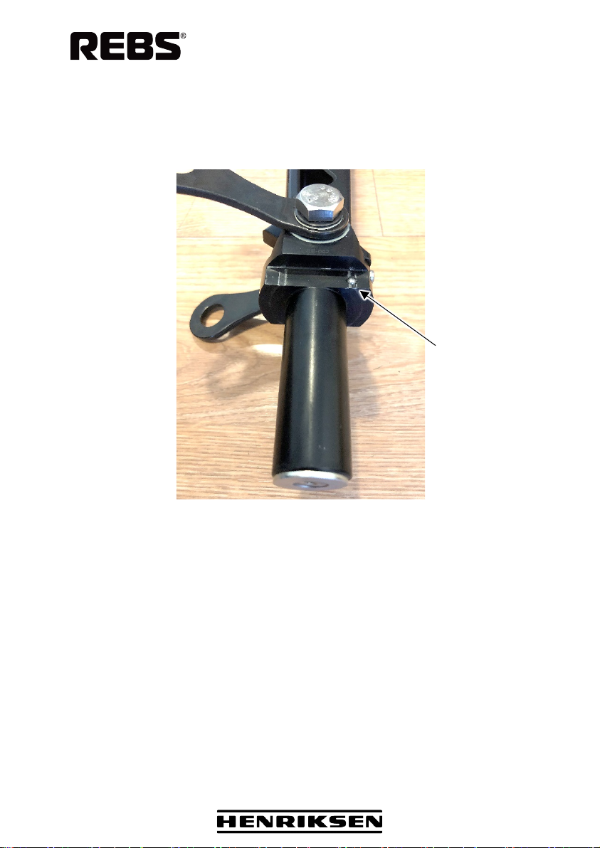
There is a spring-loaded locking ball installed in the shaft of the hook.
This device locks the hook in the top mount in addition of the magnetic
connection at the bottom of the shaft.
Figure 4: Locking ball
It is very important to make sure that the hook is attached in the right way
into the top mount (see Figure 3) to ensure the proper locking
functionality and to avoid damaging the connected parts.
Bend the hook at the shaft to unload the ball and unlock the hook.
Check this function before moving on to the next step!
Locking ball

USER MANUAL
Giraffe Tracer
Rev.: -12
page 11 of 52
M000375
3. Connect the wire ladder to the joints on the hook.
Make sure that:
- the nut at the joint is not fully tightened and the joints can
rotate if they are loaded,
- the carabiners are secured,
- the carabiners are connected properly
-the carabiners are in the correct position as shown below.
Figure 5: Carabiners connected properly

USER MANUAL
Giraffe Tracer
Rev.: -12
page 12 of 52
M000375
Secured Unsecured
Figure 6: Secured and unsecured carabiners

USER MANUAL
Giraffe Tracer
Rev.: -12
page 13 of 52
M000375
4.3 Operation
Figure 7: Preparation
Figure 8: Placing the hook

USER MANUAL
Giraffe Tracer
Rev.: -12
page 14 of 52
M000375
Figure 9: Releasing the hook
Bend the hook at the shaft by pressing the pole against the ledge
(see the red arrow at step 2) to unload the locking ball in the shaft.
This will release the hook, and now pull the pole with the top mount
downwards (retract) to disconnect the hook.
If there is not enough pressure in the system to retract the pole
properly - pull the wire ladder firmly to disconnect the hook.

USER MANUAL
Giraffe Tracer
Rev.: -12
page 15 of 52
M000375
Figure 10: Retracting the pole

USER MANUAL
Giraffe Tracer
Rev.: -12
page 16 of 52
M000375
4.4 After use
Disassembly of the pneumatic system after use:
1. Close the valve on the bottle.
NOTE: The system is still under pressure.
2. Press the retract button to release the pressure completely from
the system. Check the gauge on the regulator.
3. Disconnect the Giraffe Tracer from the regulator.
4. Disconnect the regulator from the bottle.
4.5 Filling the bottle with an external diving bottle
(workaround)
The bottle can be filled with an external diving bottle if necessary.
You need the BE004009 Fill line valve v.2 and the BE003752 External
air bottle system v.2 to connect the diving cylinder and the bottle.
NOTE: A YOKE adapter is needed for the fill line valve in case of 200 bar
diving cylinders.
Figure 11: Filling with an external diving bottle
External
diving bottle
Fill line
valve
Giraffe bottle
External air
bottle system

USER MANUAL
Giraffe Tracer
Rev.: -12
page 17 of 52
M000375
Connect and fill:
•Connect the bottles
•Open the fill line valve: rotate the wheel clockwise.
•Open the valve on the Giraffe bottle.
•Open the valve on the external bottle to start filling the Giraffe
bottle. Check the gauge on the fill line valve.
Disconnect:
•Close the valve on the external diving bottle.
•Close the valve on the Giraffe bottle.
NOTE: The system is still under pressure.
•Rotate the wheel of the fill line valve slowly counterclockwise to
release the pressurized air from the system completely.
Check the gauge on the fill line valve.
•Disconnect the bottles.

USER MANUAL
Giraffe Tracer
Rev.: -12
page 18 of 52
M000375
5 TRANSPORT
NOTE: Never transport the pole with hook attached!
5.1 On pontoon
1. The strap keeps the
pole from moving
sideways.
2. The middle strap
keeps the pole from
sliding forward.
3. The back strap
keeps the pole from
moving backwards.

USER MANUAL
Giraffe Tracer
Rev.: -12
page 19 of 52
M000375
5.2 Between seat rows
The base should have an angle
so that the pole lies flush on the
soft padding.
Secure the pole with a Velcro
strap or similar
The base has a flexible adapter,
so the pole can remain in the
base plate ready for immediate
use.

USER MANUAL
Giraffe Tracer
Rev.: -12
page 20 of 52
M000375
5.3 On the deck
Use Velcro straps to secure the pole to the three mounting bases.
Table of contents
Popular Extender manuals by other brands


EMG
EMG PA2 Installation information

Devolo
Devolo Audio Extender Specifications

Structured Cable Products
Structured Cable Products 960 operating instructions

Command access
Command access PM300UNIV installation instructions

NEW SYSTEMS INSTRUMENTS
NEW SYSTEMS INSTRUMENTS QUAD LFO user manual

Synergy Global Technology
Synergy Global Technology LCDK1042 user manual


