Table of contents
5
Table of contents
1 General information.................................... 6
1.1 Intended use ................................................. 6
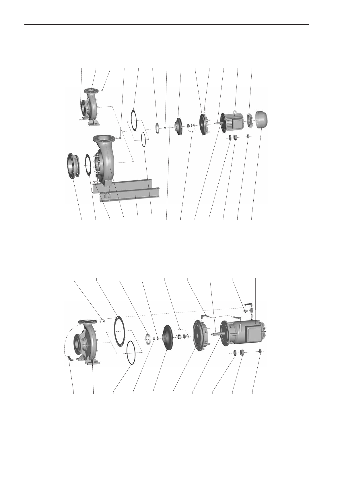
1.2 Exploded view............................................... 8
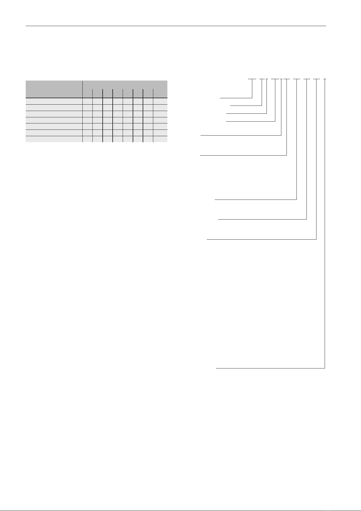
1.3 Wear parts................................................... 10
1.4 Technical specifications............................... 10
1.4.1 Model designation....................................... 10
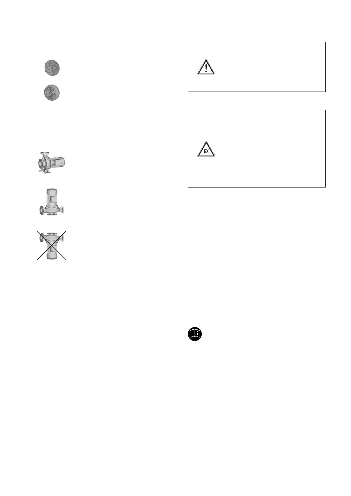
1.4.2 Impellers...................................................... 11
1.4.3 Installation................................................... 11
1.4.4 Shaft sealing ............................................... 11
1.4.5 Drive............................................................ 11
1.4.6 Dimensions, weight, performance data....... 12
1.4.7 General data ............................................... 12
2 Safety ......................................................... 14
2.1 Notes / explanations.................................... 14
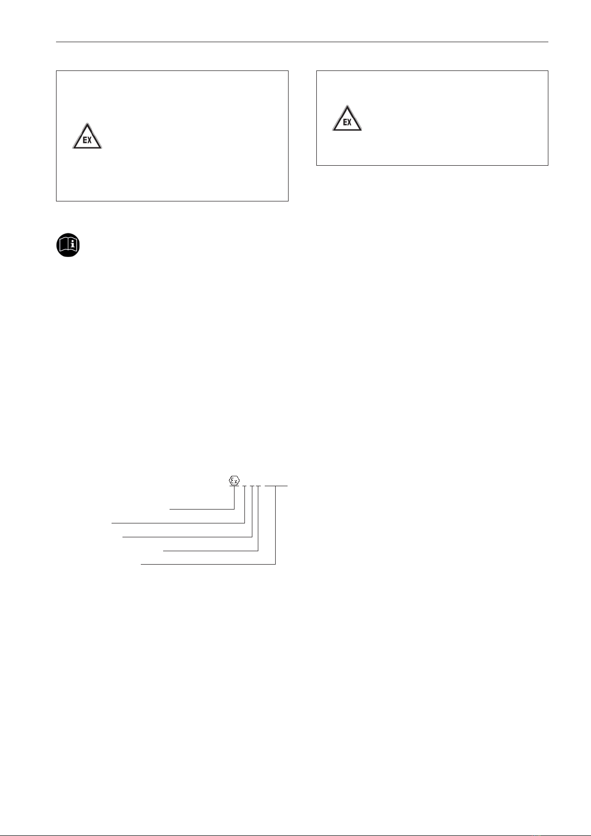
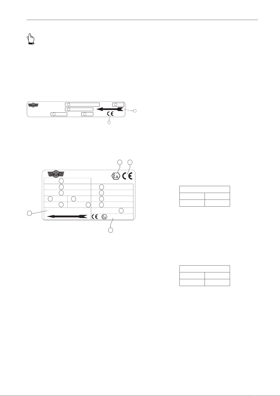
2.1.1 Machine identification.................................. 14
2.2 Integrated safety systems (optional) ........... 15
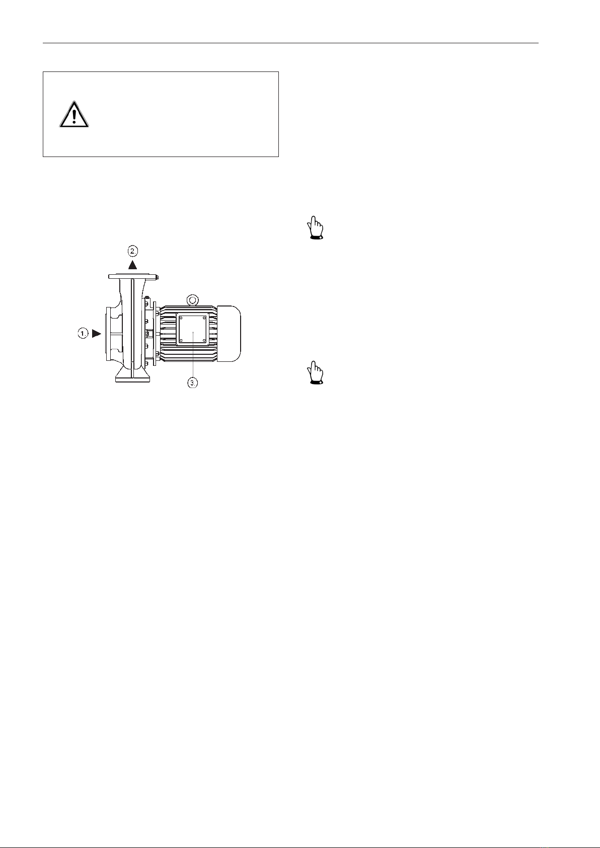
2.3 Connections on the pump ........................... 16
2.4 Safety measures ......................................... 16
2.5 Obligations of the operator.......................... 16
3 General hazard warnings ......................... 18
3.1 Dangers....................................................... 18
3.2 Danger zones on the pump......................... 18
3.3 Assembly, operation and maintenance
personnel .................................................... 18
3.4 Installation of replacement parts and wear
parts ............................................................ 18
3.5 Shut off procedures..................................... 19
4 Transport.................................................... 20
4.1 Scope of delivery......................................... 20
4.2 Transport and packaging ............................ 20
4.2.1 Delivery (including spare parts and re-
placement parts) ........................................... 20
4.2.2 Intermediate storage ................................... 20
4.3 Transport to the site of installation
(by the customer) ........................................ 20
4.3.1 Transport with a forklift truck ....................... 20
4.3.2 Transport with a crane ................................ 21
5 Installation / fitting .................................... 22
5.1 Installation................................................... 22
5.2 Dimensions ................................................. 23
5.2.1 Dimensions of GF/GF-PM model................ 23
5.2.2 Dimensions of GFC model.......................... 28
5.2.3 Dimensions of D model............................... 29
5.2.4 Dimensions of W model .............................. 31
5.2.5 Dimensions of WS model............................ 33
5.3 Technical specifications............................... 35
5.4 Electrical connection ................................... 37
5.5 Motor protection .......................................... 37
5.6 Direction of rotation check........................... 38
5.6.1 Change of direction of rotation.................... 38
5.7 Motor connection diagrams......................... 39
5.7.1 PTC thermistor connection.......................... 39
5.8 Frequency converter operation ................... 39
5.9 ETS X4........................................................ 40
5.10 Laying the pipes.......................................... 40
5.11 Frost protection ........................................... 40
6 Commissioning ......................................... 41
6.1 Operating modes and connecting
frequency .................................................... 41
6.2 Starting up................................................... 42
7 Maintenance / cleaning............................. 43
7.1 Maintenance................................................ 43
7.2 Maintenance instructions for prolonged
periods of inactivity...................................... 44
7.3 Bearing lubrication ...................................... 45
7.3.1 Relubrication unit ........................................ 45
7.3.2 Greasing intervals ....................................... 46
7.4 Seals ........................................................... 46
7.5 Cleaning...................................................... 46
7.6 Tightening torques for nuts and bolts.......... 47
7.7 Disposal ...................................................... 47
8 Disturbance / cause / trouble shooting... 48
9 Disassembly / assembly........................... 50
9.1 Disassembly................................................ 50
9.2 Assembly..................................................... 52
Table of figures
Figure 1a Exploded view (GF/GF-PM model) ............... 8
Figure 1b Exploded view (GFC model) ......................... 8
Figure 1c Exploded view (D model) .............................. 9
Figure 1d Exploded view (W/WS model)....................... 9
Figure 2a Name plate (standard) ................................ 15
Figure 2b Name plate (explosion protection pump) .... 15
Figure 3 Connections on the pump .......................... 16
Figure 4 Transport with a crane ................................ 21
Figure 5a Dimensions (GF/GF-PM model).................. 23
Figure 5b Dimensions (GFC model)............................ 28
Figure 5c Dimensions (D model)................................. 29
Figure 5d Dimensions (W model)................................ 31
Figure 5e Dimensions (WS model) ............................. 33
Figure 6 Dry running label......................................... 44
Figure 7 Relubrication label....................................... 45