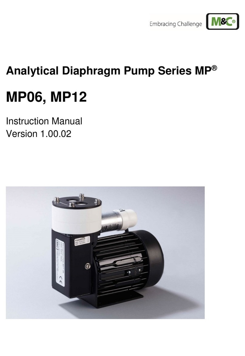
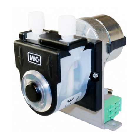
M&C SR Series User manual

Peristaltic Pump Series SR®
SR25.1, SR25.2-G, SR25.1/Ex
Instruction Manual
Version 1.01.01

2 SR25 | 1.01.01 www.mc-techgroup.com
Dear Customer,
Thank you for buying our product. In this manual you will find all necessary information about this M&C product.
The information in the manual is fast and easy to find, so you can start using your M&C product right after you
have read the manual.
If you have any question regarding the product or the application, please don’t hesitate to contact M&C or your
M&C authorized distributor. You will find all the addresses in the appendix of this instruction manual.
For additional information about our products, please go to M&C’s website www.mc-techgroup.com. There you
can find the data sheets and manuals of our products in German and English.
This instruction manual does not claim completeness and may be subject to
technical modifications.
©
02/2024 M&C TechGroup
Germany GmbH. Reproduction of this document or
its content is not allowed without permission from
M&C.
SR
®is a registered trademark.
With the
release of this version all older manual versions will no longer be valid.
The German instruction manual is the original instruction manual. In case of
arbitration only the German wording shall be valid and binding.
Version: 1.0
1.01

www.mc-techgroup.com SR25 | 1.01.01 3
Content
1General information.............................................................................................................................................4
2Declaration of conformity ...................................................................................................................................4
3Safety instructions................................................................................................................................................5
3.1 Intended use...........................................................................................................................................................................................................5
4Warranty.................................................................................................................................................................6
5Used terms and signal indications.....................................................................................................................6
6Introduction...........................................................................................................................................................8
7Technical Data.......................................................................................................................................................8
7.1 Options for SR25.1/Ex........................................................................................................................................................................................8
7.2 Dimensions..............................................................................................................................................................................................................9
8Description ..........................................................................................................................................................10
9Reception and storage.......................................................................................................................................11
10 Installation instructions.....................................................................................................................................12
10.1.1 Mounting instructions for peristaltic pump..........................................................................................................................12
11 Supply connections............................................................................................................................................13
11.1 Hose connections.............................................................................................................................................................................................13
11.2 Electrical connections ....................................................................................................................................................................................14
12 Preparations for commissioning......................................................................................................................15
13 Start-up ................................................................................................................................................................15
14 Closing down.......................................................................................................................................................16
15 Maintenance........................................................................................................................................................16
15.1 Changing the pump tubing.......................................................................................................................................................................17
15.2 Changing contact pulleys and springs................................................................................................................................................19
15.3 Reassembly of the driver..............................................................................................................................................................................20
15.4 Cleaning the pump head.............................................................................................................................................................................21
16 Repair information .............................................................................................................................................21
17 Proper disposal of the device ...........................................................................................................................21
18 Spare parts list.....................................................................................................................................................22
19 Risk assessment ..................................................................................................................................................22
20 Appendix..............................................................................................................................................................24
List of illustrations
Figure 1 Dimensions SR25.1 .......................................................................................................................................................................................9
Figure 2 Dimensions SR25.1/EX................................................................................................................................................................................9
Figure 3 Dimensions SR25.1/Ex in stainless steel enclosure (01P1250)........................................................................................10
Figure 4 Dimensions SR25.2-G...............................................................................................................................................................................10
Figure 5 Universal unit EC-FD with three built-in peristaltic pumps SR25.1..............................................................................11
Figure 6 SR25.2: Mounting distance between front panel and pump motor ..........................................................................13
Figure 7 Connection of the distribution voltage ........................................................................................................................................14
Figure 8 Changing the pump tubing ................................................................................................................................................................18
Figure 9 Different pump tube sizes.....................................................................................................................................................................19
Figure 10 Disassembly of pump head and driver.........................................................................................................................................19
Figure 11 Check of axles and rolls...........................................................................................................................................................................20
Figure 12 Overview risk assessment......................................................................................................................................................................23
Figure 13 Spare part drawing SR25.1....................................................................................................................................................................25
Figure 14 Spare part drawing SR25.2....................................................................................................................................................................26
Figure 15 EC-type examination certificate SR25.1/EX, SR25.2/EX and SR25.3/EX .....................................................................27

4 SR25 | 1.01.01 www.mc-techgroup.com
Head Office
M&C TechGroup Germany GmbH Rehhecke 79 40885 Ratingen Germany
Telephone: 02102 / 935 - 0
Fax: 02102 / 935 - 111
E - mail: info@mc-techgroup.com
www.mc-techgroup.com
1GENERAL INFORMATION
The product described in this instruction manual has been built and tested in our production facility.
All M&C products are packed to be shipped safely. To ensure the safe operation and to maintain the safe condition,
all instructions and regulations stated in this instruction manual need to be followed. This instruction manual
includes all information regarding proper transportation, storage, installation, operation and maintenance of this
product by qualified personnel.
Follow all instructions and warnings closely.
Read this manual carefully before commissioning and operating the device. If you have any questions regarding
the product or the application, please don’t hesitate to contact M&C or your M&C authorized distributor.
2DECLARATION OF CONFORMITY
CE - Certification
The product described in this operating manual complies with the following EU directives:
ATEX-Directive
The product SR25.1/Ex which is described in this manual is produced in accordance with the EU directive for devices
and protection systems for appropriate use in hazardous areas 2014/34/EU appendix II.
EMC-Instruction
The requirements of the EU directive 2014/30/EU “Electromagnetic compatibility“ are met.
Low Voltage Directive
The requirement of the EU directive 2014/35/EU “Low Voltage Directive“ are met.
The compliance with this EU directive has been examined according to DIN EN 61010.
Declaration of conformity
The EU Declaration of conformity can be downloaded from the M&C homepage or directly requested from M&C.

www.mc-techgroup.com SR25 | 1.01.01 5
3SAFETY INSTRUCTIONS
Please take care of the following basic safety procedures when mounting, starting up or operating this
equipment:
Read this operating manual before starting up and use of the equipment. The information and warnings given in
this operating manual must be heeded.
Any work on electrical equipment is only to be carried out by trained specialists as per the regulations currently in
force.
Attention must be paid to the requirements of VDE 0100 (IEC 364) when setting high-power electrical units with
nominal voltages of up to 1000 V, together with the associated standards and stipulations.
Check the details on the type plate to ensure that the equipment is connected to the correct mains voltage.
Protection against touching dangerously high electrical voltages:
Before opening the equipment, it must be switched off and hold no voltages. This also applies to any external
control circuits that are connected.
The device is only to be used within the permitted range of temperatures and pressures. For details please refer to
the technical data sheet or instruction manual.
Check that the location is weather-protected. It should not be subject to either direct rain or moisture.
The peristaltic pumps SR25.1 and SR25.2-G must not be used in hazardous areas.
Installation, maintenance, inspections and any repairs of the devices must be carried out only by qualified skilled
personnel in compliance with the current regulations.
3.1 INTENDED USE
The peristaltic pumps SR25.1 and SR25.2-G are intended for use in general purpose areas (non-hazardous
environments) only.
The peristaltic pumps SR25.1, SR25.2-G und SR25.1/Ex can only be operated in compliance with the information
starting in chapter 7. You must meet the requirements of the ambient temperature and pressure characteristics in
particular.
Do not use this product for any other purpose. Improper use and handling can create hazards and cause damage.
For more information, please refer to the safety information in this instruction manual.

6 SR25 | 1.01.01 www.mc-techgroup.com
4WARRANTY
In case of a device failure, please contact immediately M&C or your M&C authorized distributor.
We have a warranty period of 12 months from the delivery date. The warranty covers only appropriately used
products and does not cover the consumable parts. Please find the complete warranty conditions in our terms and
conditions.
The warranty includes a free-of-charge repair in our production facility or the free replacement of the device. If you
return a device to M&C, please be sure that it is properly packaged and shipped with protective packaging. The
repaired or replaced device will be shipped free of delivery charges to the point of use.
5USED TERMS AND SIGNAL INDICATIONS
Danger
means that death, serious personal injury and/or substantial property
damage will result if proper precautions are not taken.
Warning
indicates that death, serious personal injury and/or substantial property
damage might occur if proper precautions are not taken.
Caution
means that minor personal injury may result if proper precautions are not
taken.
Caution
without a warning triangle symbol, indicates that property damage may
result if proper measures are not taken.
Note
This is important information about the product or the appropriate part of
the manual to which particular attention should be paid.
Qualified personnel
These are persons who are familiar with the installation, commissioning,
maintenance and operation of the product and have the necessary
qualifications through training or instruction. Qualified personnel must
have at least the following knowledge:
•Instructed person in EX-protection (for devices used in hazardous
areas only)
•Trained person in the electrotechnical field
•Detailed knowledge of the operating instructions and the
applicable safety regulations
‘EX‘ indicates
important information about the product or about the
corresponding parts in the instruction manual, relating to usage in
potentially explosive atmospheres.

www.mc-techgroup.com SR25 | 1.01.01 7
High voltages!
Protect yourself and others against damage which might be caused by
high voltages.
Toxic!
Acute toxicity (oral, dermal, inhalation)! Toxic when in contact with skin,
swallowed or inhaled.
Corrosive!
These substances destroy living tissue and equipment upon contact.
Do not breathe vapors; avoid contact with skin and eyes.
Hot surface!
Contact may cause burn! Do not touch!
Caution, risk of being crushed due to rotating parts.
Do not open the device. Use personal protective equipment (PPE).
Wear protective gloves!
Working
with chemicals, sharp objects or extremely high temperatures
requires wearing protective gloves.
Wear safety glasses!
Protect your eyes while working with chemicals or sharp objects. Wear
safety glasses to avoid getting something in your eyes.
Wear protective clothes!
Working with chemicals, sharp objects or extremely high temperatures
requires wearing protective clothes.
Use foot protection
Use safety helmet and full protective goggles

8 SR25 | 1.01.01 www.mc-techgroup.com
6INTRODUCTION
The peristaltic pump SR25... has been specially developed for the condensate removal in analysis applications. It
ensures a continuous condensate discharge at gas sample coolers, condensate collecting vessels, etc.
Synchronous motor and gearing unit with return stop make a condensate backflow impossible. The capacity of
0.3 l/h guarantees a safe condensate removal, for example when cooling 850 l/h sample gas with an inlet dew point
of +70 °C [158 °F] to a temperature of 5 °C [41 °F].
7TECHNICAL DATA
Peristaltic pump series SR25®
Version SR25.1
Version SR25.2-G
Version SR25.1/Ex
Part No.
01P1000
01P1120
01P1201
Housing
No
Yes, out of PVC
No
Method of mounting
Surface-mounted/
built-in
Wall mounting
Surface-mounted/ built-in
Protection/electrical standard
IP 10 EN60529
IP 52 EN60529
IP40, II 2 G EEx m II T5
certificate no. KEMA
03ATEX2218 X
Electrical connection
Terminals 1.5 mm2
Terminals 1.5 mm2
1 x M20 x 1.5
600 mm [≈ 23.6“] cable 4 x
0.5 mm2with cable gland
M12 x 1.5
Dimensions (W x H x D)
80 x 110 x 130 mm
[≈ 5.12“ x 4.33“ x 3.15“]
105 x 126 with cable gland x
106.5 mm [4.1” x 5.0” with
cable gland x 4.2”]
80 x 110 x 130 mm
[≈ 5.12“ x 4.33“ x 3.15“]
Weight
0.6 kg [≈ 1.32 lb]
0.8 kg [≈ 1.76 lb]
0.7 kg [≈ 1.54 lb]
Peristaltic pump speed
5 rpm standard
Capacity
0.3 l/h standard
Pressure min..
200 mbar abs.
Pressure max.
2200 mbar abs.
Sample temperature
0 to +60 °C [32 to 140 °F]
Ambient temperature
0 to +50 °C [32 to 122 °F]
+5 to +50 °C [41 to 122 °F]
Storage temperature
-10 to +60 °C [14 to 140 °F]
Connections
Tube connections DN 4/6 mm
Material of sample contacting parts
PVDF, Novoprene
Power supply / consumption
115/230 V 50/60 Hz, 3.5 VA
Continuous duty
100 %
7.1 OPTIONS FOR SR25.1/EX
Part No.
SR25.1/Ex with Ex connection box and enclosure
01P1250 1 x SR25.1/Ex peristaltic pump with Ex connection box and SS enclosure for one peristaltic pump,
dimensions of the SS enclosure with wall brackets (W x H x D): 205.5 x 240 x 179 mm [≈ 8.1" x 9.4" x 7.0"]
01P1260
2 x SR25.1/Ex peristaltic pumps with Ex connection box and SS enclosure for up to 4 peristaltic pumps,
dimensions (W x H x D): 400 x 235 x 175 mm [≈ 15.7“ x 9.3“ x 6.9“]
01P1270
3 x SR25.1/Ex peristaltic pumps with Ex connection box and SS enclosure for up to 4 peristaltic pumps,
dimensions (W x H x D): 400 x 235 x 175 mm [≈ 15.7“ x 9.3“ x 6.9“]
01P1280
4 x SR25.1/Ex peristaltic pumps with Ex connection box and SS enclosure for up to 4 peristaltic pumps,
dimensions (W x H x D): 400 x 235 x 175 mm [≈ 15.7“ x 9.3“ x 6.9“]

www.mc-techgroup.com SR25 | 1.01.01 9
Option Ex-connecting box for
SR25.1/Ex
Version for one peristaltic pump
Version for 4 peristaltic pumps
Part number
01P9400
01P9405
Electrical connections/cable glands
Terminals max. 4 x 2.5 mm
2
/1 x
M20 x 1.5, 1 x M12 x 1.5
Terminals max. 16 x 2.5 mm
2
/1 x M20 x
1.5, 4 x M12 x 1.5
Protection/electrical standard
IP65, II 2 G EEx e II T5
Dimensions (W x H x D)
75 x 80 x 55 mm [≈ 2.95“ x 3.15“ x 2.17“]
160 x 75 x 55 mm [≈ 6.3“ x 2.95“ x 2.17“]
Weight
0.35 kg [≈ 0.77 lb]
0.6 kg [≈ 1.32 lb]
7.2 DIMENSIONS
Figure 1 Dimensions SR25.1
Figure 2 Dimensions SR25.1/EX

10 SR25 | 1.01.01 www.mc-techgroup.com
Figure 3 Dimensions SR25.1/Ex in stainless steel enclosure (01P1250)
Figure 4 Dimensions SR25.2-G
8DESCRIPTION
The peristaltic pump SR25.1 is self-suctioning and designed for continuous operation. It consists of 3 compact
parts:
•synchronous motor,
•gearing unit with return stop,
•pump.
The slow speed (5 rpm) of the two PVDF hose contact pulleys together with the novoprene hose guarantee a good
mechanical and chemical resistance with a long service life.

www.mc-techgroup.com SR25 | 1.01.01 11
Note
The compatibility of the tube material with unknown gases has to be checked before
using.
The use of ready-made tubing sets means that tubing can be changed easily and without the use of tools. The
screw-on DN4/6 tubing connections also allow the connection of PTFE tubing.
The peristaltic pump SR25.1... is supplied with electric mains for 230 V/50 Hz and 115 V/60 Hz.
•The peristaltic pump SR25.2-G is supplied in a wall-mount housing.
•Up to 4 peristaltic pumps SR25.1 can be installed in the universal unit EC-FD.
•Up to 4 peristaltic pumps SR25.1Ex can be installed in the universal unit EC-D/EX.
Figure 5 Universal unit EC-FD with three built-in peristaltic pumps SR25.1
9RECEPTION AND STORAGE
The peristaltic pump is a complete pre-installed unit.
•Carefully inspect the peristaltic pump and any special accessories included with it immediately on arrival
by removing them from the packing and checking for missing articles against the packing list !
•Check the items for any damage in transit and, if required, inform the shipping insurance company
immediately of the damage found !
Note
The peristaltic pump must be stored in a weather protected frost-free area!

12 SR25 | 1.01.01 www.mc-techgroup.com
10 INSTALLATION INSTRUCTIONS
When installing the pump make certain that accident prevention regulations and safety instructions including
those for subsequent operation are observed. The safety instructions in section must be observed.
The following ambient conditions must be observed:
•Ambient temperature: max. +50 °C [122 °F]
•The pump must be protected against water and dust.
•In operation a sufficient cooling air supply must be guaranteed.
Danger
The peristaltic pumps SR25.1 and SR25.2-G must not be operated in hazardous areas.
Note
The pump must only be used in the conditions specified in the technical data. The
pump should be
installed away from heat sources and freely ventilated to prevent
any accumulation of heat.
For outdoor installation, the pump must be installed in a housing protected from
frost in the winter and sufficiently ventilated in summer. Exposure to direct sunlight
must be avoided.
Danger
It is therefore essential to provide protection for persons against contact with alive
parts (e.g. electrical connections, motor windings) and moving parts (e.g. fan).
Protection against the entry of foreign bodies must also be provided.
10.1 MOUNTING INSTRUCTIONS FOR PERISTALTIC PUMP SR25.2
Make sure to mount the pump to the front of the cooler with a minimum distance of 3.5 mm [≈ 0.138”] and a
maximum distance of 5.5 mm [≈ 0.216”] between the pump motor and the front panel. The minimum distance
avoids damage to the pump motor and the maximum distance prevents the motor shaft from getting loose.

www.mc-techgroup.com SR25 | 1.01.01 13
1 Pump head (outside the device housing) 2Device front panel
3Recommended mounting distance 4Pump motor (inside the device housing)
Figure 6 SR25.2: Mounting distance between front panel and pump motor
11 SUPPLY CONNECTIONS
11.1 HOSE CONNECTIONS
The tube connections are on the upper side of the pump. The standard threaded hose couplings are DN4/6. Tube
connections with hose nipples are available as an option (see spare parts list chapter 18).
Note
Do not mix up hose-
/tube connections for sample gas inlet and outlet; the
connections are
marked accordingly! Check for tightness of all sample lines after
connection!
The hoses are to be assembled as follows:
1. Remove the union nut from the sealing ring couplings by turning it anti-clockwise. The nut should be
removed from the thread with great care so as to ensure that the loose sealing ring in the nut is not lost.
2. Place the union nut over the connecting hose.
3. Place the sealing ring over the connecting hose with the thicker bead towards the nut.
4. Place the hose over the nipple on the thread.
5. The union nut is to be screwed tight by hand.
The hose will no longer be able to slip off and is now compression-proof.

14 SR25 | 1.01.01 www.mc-techgroup.com
Note
The tightness of the connections can only be guaranteed if the connection hose has
a straight rim (use a hose cutter).
Aggressive condensate is possible.
Chemical burns caused by aggressive media possible!
Wear protective gloves and protective glasses!
Wear proper protective clothing!
11.2 ELECTRICAL CONNECTIONS
Connect the cables for the power supply as follows:
Figure 7 Connection of the distribution voltage
Danger
Incorrect system voltage can damage the unit. When establishing connections, check
that the system voltage corresponds with the voltage shown on the type plate!
The supply voltage is only allowed to deviate max. +6% resp. -10% from the indication
on the model type plate.
Note
Attention must be paid to the requirements of IEC364 (DIN VDE 0100) when setting
high-power electrical units with nominal voltages of up to 1000V, together with the
associated standards and stipulations.
Power
Power

www.mc-techgroup.com SR25 | 1.01.01 15
The electrical connection of the SR25.1/Ex must be done in a separate EExe box with the cable gland M12 x 1
included:
230 V - blue and red
115 V - blue and white.
Danger
The respective cable which is left (230 V white and 115 V red) must be connected at
a separate terminal.
•The main circuit of the pump type SR25.1,SR25.1/EX and SR25.2-G must be equipped with a fuse (0.25 A
recommended) corresponding to the nominal current (over current protection EN 60335-1);
•An appliance to separate the motor from the power is to be provided in the electrical installation (EN 60335-
1);
•The pump must be installed so that contact with alive parts (connections, possibly windings) is impossible.
12 PREPARATIONS FOR COMMISSIONING
Before initial startup, all plant- and process-specific safety measures must be observed. It is mandatory for the
operator to complete the enclosed risk assessment of the product.
The gas exposure risk must be assessed by the operator with regard to the hazards posed by process and calibration
gas and the setup at the installation site (e.g. tubing, system cabinet/container/plant). If the risk assessment reveals
increased exposure hazards, further measures are required.
A visible label must be attached to the installation site in accordance with the risk assessment provided by the
operator.
13 START-UP
Specific safety instructions for media being handled must be observed. Before pumping a medium, the
compatibility of the flexible tube material with the medium must be checked. The following steps should be carried
out before initial start-up:
•The maximum permissible operating pressure (see technical data) must not be exceeded, even when the
flow is restricted.
•Ambient conditions: see technical data.

16 SR25 | 1.01.01 www.mc-techgroup.com
14 CLOSING DOWN
Note
The area in which the pump is situated when not in use must be kept free of frost at
all times!
If the pump is putting out of action be sure that the pressure in the lines is atmospheric.
On short-term decommissioning of the peristaltic pump no special measures need to be taken.
For long-term decommissioning, it is recommended to flush the peristaltic pump with ambient air or inert gas.
A flushing time of 3 to 5 minutes is sufficient under normal conditions.
Warning
Aggressive condensate is possible.
Chemical burns caused by aggressive media possible!
When disassembling, repairing or cleaning, wear safety glasses and proper
protective clothing!
15 MAINTENANCE
Before the maintenance work is carried out, it is necessary that the specific safety procedures pertaining to the
system and operational process are observed!
Danger
Dangerous voltage!
It is necessary to take the pump off the mains before any assembly, maintenance or
repair work is carried out!
Aggressive condensate is possible.
Chemical burns caused by aggressive media possible!
Wear protective gloves and protective glasses!
Wear proper protective clothing!

www.mc-techgroup.com SR25 | 1.01.01 17
Warning
Explosion hazard due to wear and tear!
Therefore, a regular inspection of all pump components is necessary
according to the following maintenance plan.
Flexible tube, conveying belt, contact pulleys and contact springs are the only parts of the pump subject to wear.
They are simple to change.
Note
If you send back the peristaltic pump to the M&C service for repair, please let us know
what kind of condensate has been pumped.
Before sending the pump back clean all parts from dangerous or highly aggressive
contaminants.
Inspect the following pump
components
Action
Pump
Check pump for damage of the enclosure and any leakage in regular
intervals, at least two times per year.
Driver
After 5000 operating hours or after ½ year at the latest
Conveying belt
After 5000 operating hours or after ½ year at the latest
Motor/transmission
After 5000 operating hours or after 2 years at the latest
Fittings, connections, inlets
Check in suitable intervals. Replace when damaged with original parts in
perfect condition.
Equipotential bonding
Check equipotential bonding between pump enclosure and motor. The
equipotential bonding needs to be lower than 0.3 Ohm. Use lock washers
for the screws.
Additional components,
accessories
During scheduled maintenance work, check any additional components or
accessories, e.g. filter installed upstream, separators and gas coolers, if they
are in proper working condition.
Warning
Components like cable fittings and protective plugs can only be replaced by
equal parts with a type examination certificate.
15.1 CHANGING THE PUMP TUBING
Aggressive media residues possible.
On disassembly, repairing or cleaning of the hose pump, wear protective
glasses and appropriate protective clothing!

18 SR25 | 1.01.01 www.mc-techgroup.com
Warning
If you return the hose pump to M&C customer service for repair, we will ask for
information concerning the delivered liquid.
The pump should be cleaned of hazardous or highly aggressive contaminants
prior to return shipment.
1
Conveying belt
2
S-bolt
3
Tubing set
4
contact pulley
5
springs
Figure 8 Changing the pump tubing
For changing the pump tubing please proceed as follows:
1. Unplug the pump from the mains voltage. The device needs to be voltage free.
2. Open tube connections at the pump;
3. Press conveying belt at the recessed grips and turn S-bolt clockwise up to limit stop;
4. Take away conveying belt and remove the old tubing set from the guides by pulling on the tube
connectors;
5. Press the two contact pulleys and check whether the spring pressure is still sufficient, if not, the contact
springs have to be changed (see chapter 15.2);
6. Put the new tubing set with the tube connectors into the guides of the conveying belt ;
Warning
Only the usage of the original tubing set guarantees a proper functionality.
Never lubricate the tube.
Before mounting the pump check all parts for contaminations and clean if necessary.
7. Put the conveying belt with the new tubing into the dovetail guide of the pump body;
8. Press conveying belt at the recessed grips and simultaneously turn the S-bolt anticlockwise until it snaps;
9. Switch on pump.

www.mc-techgroup.com SR25 | 1.01.01 19
Figure 9 Different pump tube sizes
15.2 CHANGING CONTACT PULLEYS AND SPRINGS
Note
While mounting, make sure that the center of rotation and the driver are aligned.
Use genuine spare parts only!
Follow these instructions to change the contact pulley and springs:
1. Disconnect the peristaltic pump from power supply
2. Unscrew nuts of the pump head (wrench size 5.5)
1
Pump head nuts
2
Pump head
3
Springs
4
Groove
5
Driver (roll carrier)
6
Collar of the shaft bore
Figure 10 Disassembly of pump head and driver
3. Remove the pump head from the motor shaft
4. Now the driver can be removed from the pump head and is ready for maintenance.
5. The removal of the springs 4 pcs.) away from the driver is easily possible without the aid of any tools. For
this take spring out of the groove near to the shaft bore.

20 SR25 | 1.01.01 www.mc-techgroup.com
6. Dismount roller axes and change contact pulleys. Take care that axles are not worn out by the springs and
have damaged the dent at the axles front end. The axles must be replaced when worn out (see Figure 11).
Figure 11 Check of axles and rolls
Note
The springs may come in different colorings. This is not a quality impairment. Make sure
to use the right spring strength. This can be identified by the spring wire diameter. The
‘standard version for Novoprene pump tubing’ (Part No. 90P1010) has a diamete
r of
1.1 mm and the ‘reinforced version for FKM-, Acidflex®- or Masterflex®-
tubing’ (Part No.
90P1015) has a diameter of 1.2 mm.
Note
Two different types of springs are mounted inside the driver (right and left springs) for
the first delivery. When spare springs are ordered, for simplified storage, only one type
will be delivered (right spring) which can be used for all four springs and will replace
without any problems the initial springs. The replacement springs guarantee full
functionality when all four springs are replaced.
•Make sure that contact pulleys roll easily on the axles. After remounting the axles with contact pulley into
the driver the spring has to be mounted as shown in Figure 11. Please pay attention to the alignment of
the dent.
15.3 REASSEMBLY OF THE DRIVER
Reassemble the driver in reverse order:
1. Insert the roll carrier back into the pump head
2. Push the pump head with the roll carrier onto the motor shaft
3. Tighten the nuts of the pump head fastening (SW 5.5) .
The dent prevents
rotation of the axle
New
Worn out
Other manuals for SR Series
1
This manual suits for next models
3
Table of contents
Other M&C Water Pump manuals
Popular Water Pump manuals by other brands

Berkeley
Berkeley B1-1/2XQBS-11 owner's manual

GORMAN-RUPP PUMPS
GORMAN-RUPP PUMPS 16A2-4045T manual

Edelbrock
Edelbrock For Big-block Chevrolet V8 8850 installation instructions

Graco
Graco 237282 Instructions-parts list

Pfeiffer Vacuum
Pfeiffer Vacuum HEPTA 630 P operating instructions

Graco
Graco LubeMaster instructions

Schmalz
Schmalz EVE-TR-M operating instructions

Sealey
Sealey WPL117A instructions

Siccom
Siccom ECOTANK+ manual

Alphacool
Alphacool Eisdecke D5 Top quick start guide

Ceco Environmental
Ceco Environmental DEAN PUMP DL200 Series Installation, operation & maintenance manual

Wilden
Wilden Original Series operation & maintenance