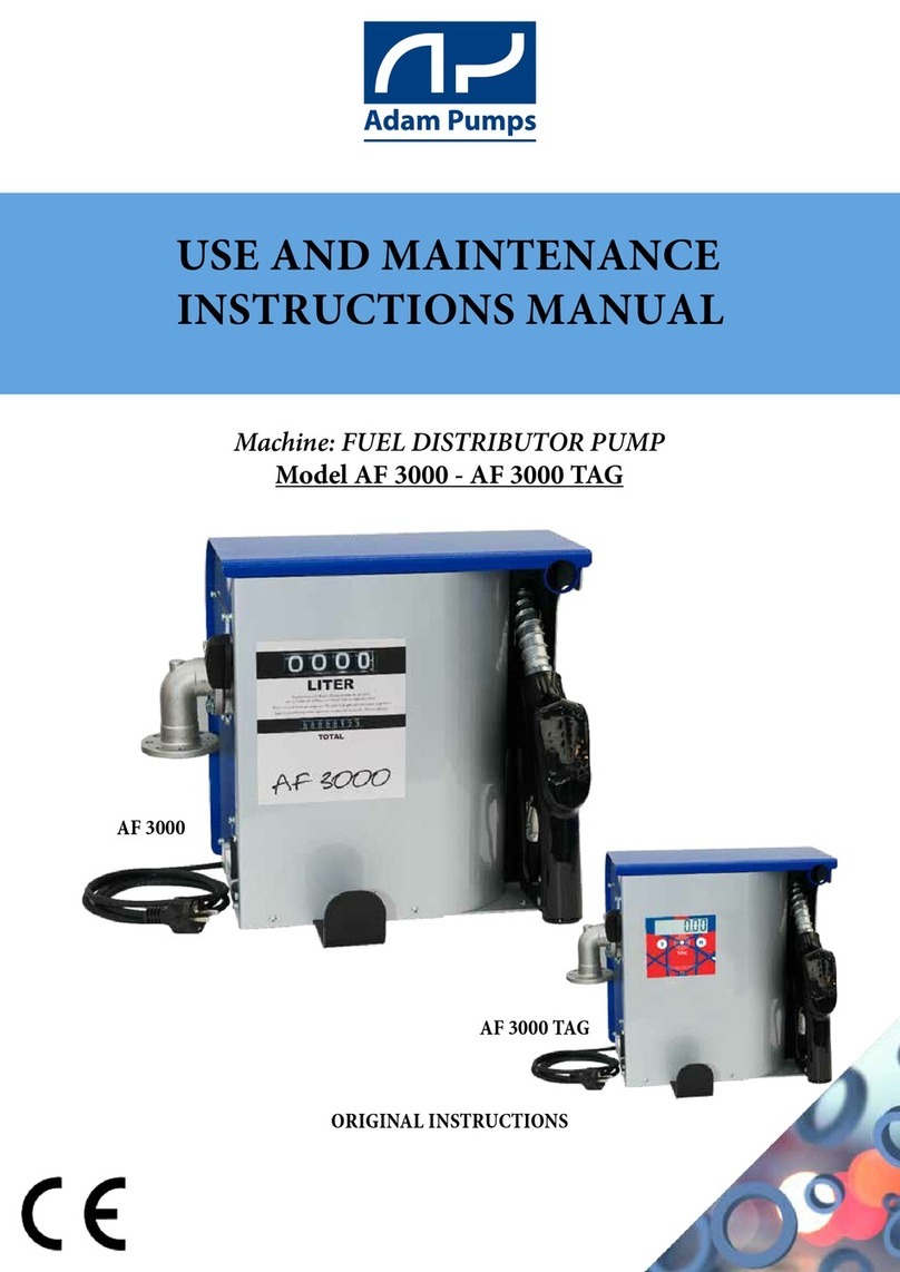
Adam Pumps G FLOW Setup guide

Adam Pumps S.p.A.
Soc. con Socio Unico
via della resistenza 46/48 - 41011 Campogalliano (MO) ITALIA
Tel +39 059 528128 - Fax +39 059 528437
UM021
7/2020 - rev. 5
G FLOW, G FLOW PULSI,
G FLOW REED
ITALIANO
(lingua originale)
ENGLISH
(translation of original instructions)
IT
EN

EN
Month Year
FAC-SIMILE
EC DECLARATION OF CONFORMITY
The undersigned:
ADAM PUMPS S.p.a.
Via della Resistenza, 46/48 -41011, Campogalliano (MO), ITALY
DECLARES, under its own responsibility, that the equipment described:
Description: Electronic Meter
Models: G-FLOW DISPLAY, G-FLOW PULSI, G-FLOW REED SWITCH
Year of construction: refer to the production date printed on the label affixed to the product, it complies the legal requirements in the
directives:
the use and maintenance manual must be carefully stored near the machine in an environment
protectedagainsthumidityandheat.Themanualmustaccompanythemachineifsold.Itisprohibited
to damage, modify or remove any part of the manual.
Machine: DIESEL FUEL METER WITH GEARS
Models: G FLOW, G FLOW PULSI, G FLOW REED
USE AND MAINTENANCE MANUAL
Directive 2014/30/EU of the European Parliament and of the Council of 26 February 2014 on the harmonisation of the laws of the
Member States relating to electromagnetic compatibility.
The documentation is available to the relevant authority, against a justified request, from ADAM PUMPS S.p.a. or by sending a
request to: [email protected]
The person authorised to compile the technical le and draw up the declaration is Davide Stassi as legal representative.
Place and date of the document
Campogalliano, January 14, 2020
The legal representative
TABLE OF CONTENTS
1 - GENERAL WARNINGS
2 - SAFETY INSTRUCTIONS
2.1 Safety measures
2.2 First aid
2.3 Protective devices
2.4 Packaging
2.5 Contents
3 - OPERATING CONDITIONS
3.1 Environmental conditions
3.2 Allowed fluids / Forbidden fluids
3.3 LCD display (Only Display version)
3.4 Display orientation
3.5 User Controls - key
4 - INSTALLATION
4.1 General information
4.2 G-FLOW Display
4.3 G-FLOW PULSE Outlet
4.4 G-FLOW REED Outlet
5 - INTENDED USE
5.1 Main screens
5.2 Partial
5.3 Total (non-resettable)
5.4 Period total (partial is resettable)
5.5 Remaining stock
5.6 Minimum stock level alert
5.7 Last refuelling operations
5.8 Instant flow rate
6 - CALIBRATION
6.1 Definitions
6.2 Calibration procedure
6.3 Selecting the unit of measurement
6.4 Custom unit of measurement
6.5 Factory reset
7 - TROUBLESHOOTING
8 - MAINTENANCE
8.1 Replacing the batteries (Only Display
version)
8.2 Cleaning
9 - DEMOLITION AND DISPOSAL
10 - WARRANTY
11 - TECHNICAL SUPPORT

EN
1 - GENERAL WARNINGS
2 - SAFETY INSTRUCTIONS
2.1 Safety measures
IMPORTANT: It is essential to have understood the entire instruction manual before
performing any operation, so as to safeguard operator safety and to avoid potential product
damage.
CAUTION: Live equipment.Contact between the power supply and the liquid to be pumped must be
prevented at all costs. Connect all equipment in the work area to the earthing system. Immediately stop
operation in the event of electrostatic discharges or if you feel a shock. Do not use this device until the
problem has been identified and duly solved.
CAUTION: Flammable liquids.Observe the precautions against the risk of fire or explosion. Read
the safety data sheets to know the specific hazards of the fluids used. If there are flammable liquids in
the work area (petrol, glass cleaning liquids, etc.), you must be aware that the vapours produced can
ignite and explode. Only use the product in well-ventilated areas to prevent fires and explosions. Do
not connect or disconnect the power cables or turn the lights on and off in the presence of flammable
vapours.
Storing the manual: This manual must be kept intact and fully legible. The end user and the skilled technicians
authorised with installation and maintenance of the product in question must be able to consult it at all times.
Reproduction rights: This manual is the property of ADAM PUMPS S.p.A., which is the sole owner of all
rights provided for by applicable law, including without limitation copyright rules. All rights under these rules belong
to ADAM PUMPS S.p.A.: reproduction, even partial, of this manual, its publication, modification, transcription, public
disclosure, distribution, marketing in any form, translation and/or development, loan, or any other activity reserved by
law to ADAM PUMPS S.p.A.
2.3 Protective devices
Protective equipment characteristics: Wear equipment that is appropriate for the operations to be carried
out. Wear equipment that is resistant to the products used
CAUTION: Dangerous liquids. Read the safety data sheets to know the specific hazards
of the fluids used. When pouring dangerous liquids, always follow the safety measures
provided by the liquid manufacturer. Keep dangerous liquids in approved containers and
dispose of them in compliance with the applicable guidelines.
IMPROPER USE OF THE PRODUCT
Improper use can result in serious injury or death.
Do not operate the unit when fatigued or under the influence of alcohol or drugs.
Do not leave the work area while the product is powered or under pressure.
Turn all equipment off when not in use.
Do not blow compressed air through the meter.
Prevent liquids from drying inside the meter.
Do not alter or modify the product. Alterations or modifications to the product may invalidate the approvals and cause safety
hazards.
Place the pipes and cables away from traffic, sharp edges, moving parts, and hot surfaces.
Do not twist or bend the hoses too much, do not move the product by the hoses.
Keep children and animals away from the work area.
Observe all of the safety regulations in force.
ALWAYS KEEP A WORKING FIRE EXTINGUISHER IN THE WORK AREA.
In case of contact with EYE, SKIN, INHALATION INGESTION and refer to the fluid OF SAFETY DATA used.

EN
Personal Protective Equipment to be worn:
Safety footwear Protective clothing Protective gloves Safety goggles
2.4 Packaging
G-FLOW is supplied in a box bearing a label with the following data:
- Product - Product version - Gross weight
- Flow direction of the uid (Up, Down, Right, Left)
2.5 Contents
Open the package with a pair of scissors or a cutter.
Qty COMPONENT
1G-FLOW meter
1 USE AND MAINTENANCE MANUAL
3 - OPERATING CONDITIONS
3.1 Environmental conditions
3.4 Display orientation
3.3 LCD display (only display version)
3.2 Allowed uids / Forbidden uids
ALLOWED DIESEL FUEL (only diesel version) with 2 to 5.5 cSt viscosity (at 38°C).Minimum flash point (MF): 55°C OIL
(only oil version) with 10 to 2000 cSt viscosity (at 40°C).
FORBIDDEN PETROL, LAMMABLE LIQUIDS (MF <55°C), SOLVENTS, FOOD LIQUIDS, CORROSIVE CHEMICALS, WATER
The LCD display on the G-FLOW has a numerical register and
different instructions that are displayed only when appropriate.
1. Partial register, total register and instructions
(ALERT, STOCK and PARTIAL TOTALISER)
2. Flat battery indicator
3. TOTAL key
4. RESET key
The regular shape of the G-FLOW meter allows the LCD display mask to rotate in 90° steps.
To rotate the LCD screen:
1. Unscrew the 4 screws holding the mask to the flow meter’s body
2. Turn the mask to the desired position, being careful not to disconnect or damage the signal cable
between the display and the REED sensors.
3. Tighten the 4 screws holding the mask to the flow meter’s body.
Temperature: min. -20°C / max. +60°C (*) Relative humidity: max. 90%
(*) Caution! The temperature limits shown refer to the components making up the meter and should be
respected to prevent any damages or malfunctions from occurring.
1
3
2
4
3.5 User controls - key
press normally press and hold
G-FLOW is equipped with two keys that perform the main
functions (TOTAL and RESET)

EN
4 - INSTALLATION
4.1 General installation
The G-FLOW meter has 1” or 3/4” threaded inlets and outlets, depending on the fluid with which it has
been calibrated. The meter is designed for fixed installation on a line.
2
1
1
2
3
1
4.2 Installing the G-Flow display
4.3 Installing the G-Flow pulse outlet
The G-FLOW meter with display is delivered pre-calibrated by the manufacturer and ready for
installation.
The G-FLOW PULSE Outlet version has a calibrated pulse outlet; the meter must be connected with the 3
cables, as shown in the diagram, and the electrical specifications must be respected.
1. yellow + 12V DC
2. brown GND (0 V)
3. green PULSE OUT (100 Pulses/Litre)
4.4 Installing the G-Flow reed outlet
The G-FLOW REED Outlet version has a non-calibrated pulse outlet; the meter must therefore be
connected with the 2 cables, as shown in the diagram, and the electrical specifications must be respected.
Electrical specifications:
Max voltage : 200 VDC - 140 VAC
Max current : 0.5 ADC – 0.35 ADC
Max output : 10 W – 10 VA
Type of contact : Normally Open (NO)
Pulses per litre: 79-80 pul/litre
5 - INTENDED USE
5.1 Main screens
The device automatically switches on when dispensing starts or when either the Reset key (R) or the Total
key (T) is pressed once. The display automatically switches off if no operation is performed or if no signal
is detected for 120 consecutive seconds. Each time the meter is switched off the “Partial” screen is reset,
therefore it does not need resetting at the rst refuelling after switch-off. When the ow meter is switched
on it displays the “Partial” screen, which is the screen it automatically returns to if no key is pressed for 10
seconds. There are ve main screens you can navigate through simply by pressing , plus the log of the
last ve refuelling operations carried out, which you can navigate through simply by pressing .
Starting on the “Partial” screen, press to navigate through the last ve refuelling operations carried
out. To go back to the home screen wait for 10 seconds without pressing any key.
1. BROWN - GND
2. WHITE - REED OUT
Important:Do not use conical connections that can damage the body of the meter or the
connection flange. When installing position the suction filter.
Important: Due to the different operating conditions, pre-calibration may be different
than the one required; it is therefore recommended to calibrate the meter with each
installation (see CHAP. 6).

EN
5.2 “PARTIAL” screen
5.3 “TOTAL” screen
5.4 “TOTAL PERIOD” screen
5.5 - “REMAINING STOCK” screen
Displaying 4.2 digits, it is accessed with the meter off and by pressing
any key or by starting dispensing. With the meter on and with any screen
displayed, simply wait 10 seconds without pressing any key to display
the partial.
Access by pressing . Displaying 6 digits, no decimal point, shows the total amount of litres dispensed from the first use.
The number cannot be reset.
Access by pressing .Displaying 5.1 digits, shows the total amount of litres dispensedin a certain period of time.Thisnumber
canbe reset by pressing )
Access by pressing .Displaying 5 digits, no decimal point, shows the remaining stock in the
storage tank. To set this stock, go to the “Stock” screen and press . The value displayed will start ash-
ing and can then be changed as required by pressing to increase it or o decrease it. To quickly
increase or decrease it, press and hold or . To conrm wait 10 seconds without pressing
any key, until the meter automatically returns to the “Partial” screen.
This screen is taken as a starting reference for the description of the other screens.
5.6 “MINIMUM STOCK LEVEL ALERT” screen
Access by pressing . Displaying 5 digits, no decimal point, settable at a maximum value of

EN
5.7 “LAST REFUELLING” screen
Access by pressing . Displaying 4.2 digits that are always shown, allows you to navigate
through the last 5 refuelling operations. Each time is pressed, the dispensing number is displayed
followed by the dispensing value carried out. The refuelling operations in the log can be summed up by
pressing based on which position you are in in the log. If you are displaying, for example, the fourth
refuelling, press to display T-04- and then the value obtained from the sum of the 4 previous refuelling
operations is subsequently displayed. This can be done from any position in the refuelling log.
5.8 Instant ow rate
Access by pressing while refuelling. The screen instantly displays the fluid flow rate measured.
65000 litres. This number identies the minimum amount of liquid in the storage tank, below which the ow meter signals a
Stock alert. To set this stock, go to the “Alert” screen and press The value displayed will start ashing and can then be
changed as required by pressing to increase it or to decrease it. To quickly increase or decrease it, press and hold
or To conrm wait 10 seconds without pressing any key, until the meter automatically returns to the “Partial”
screen. NOTE The alert is disabled if 0 is set.
6 - CALIBRATION
6.1 Denitions
Fluid litres = Fluid weighed ÷ Fluid density
Flow rate (in litres per minute, LPM) = Fluid litres ÷ Fluid dispensing time (in seconds) · 60
Fluid: Engine oil type SAE10W4 Diesel fuel
Temperature: 20°C 38°C
Flow rate: 6 - 60 L/min 10 - 120 L/min
Even if the user has made some changes, the default calibration factor can be reset with a simple
procedure.
The calibration factor set by default at the factory is 79.00. This calibration factor guarantees maximum
precision under the following conditions of use:
6.2 Calibration procedure
Starting on the “Partial” screen, ll the container up to a measured quantity (more than 5L); it is important

EN
CAUTION: if the amount of liquid dispensed is less than 5 litres, the device
will not allow calibration and will display an error.
For conrmation, the last quantity dispensed will be displayed ashing in the
current Unit of measurement
Icrease or decrease this quantity by pressing or until the correct
value is reached. Wait 10 seconds for the new calibration to be automati-
cally conrmed. With the new calibration the litres will be displayed on the
“Partial” screen and in the last 5 refuelling operations carried out they will be
adapted to the new calibration. The general total and the period total re-
main unchanged.
6.3 Selecting the unit of measurement
The system has 4 standard units of measurement (Litres-US Gallons-Quarts and Pints) plus one “Custom” unit that can be
congured by the user. How to select the unit of measurement: On the “Partial” screen do not press any key for 10 seconds.
1. Press to enter Unit of measurement mode where the word “Unit” is displayed.
2.Press to conrm.
3.Press to scroll through the units of measurement available: “litres”- “us-gal” –“quarts” – “pints” – “custom”.
4. Press to conrm.
1818
1616
1414
1212
16 18,516 18,5
6.4 Custom unit of measurement
The CUSTOM unit of measurement is factory set at a decalitre (10 litres). This value can be set by the customer as follows:
Repeat the operations from point 1 to point 5 in paragraph 3.5.3 “Selecting the unit of measurement”. When the meter has con-
rmed the custom unit of measurement with , it will propose the ashing default value of
0.100. To obtain this coefcient, simply follow the custom/litre operation. E.g. if you wish to obtain a custom unit (1.00) for every
0.33 litre can, divide 1/0.33= 3.03 and enter this new coefcient. Increase or decrease this value by pressing or until
the desired value has been reached, bearing inmind that the reference unit of
measurement is in litres. Once the set value is displayed, wait 10 seconds without pressing any key for the meter to conrm.
6.5 Factory reset
The factory reset procedure can only be performed by qualified personnel. If this operation needs to be
carried out, contact technical support (Chap. 11).
that the ow rate per minute is more than 10 litres and that, while dispensing, it is not topped up as cali-
bration would be inaccurate. Fully open the nozzle. If the amount displayed does not match the measured
quantity, the meter must be calibrated.
Press to enter Calibration mode where the word “CAL” is displayed.

EN
7 - TROUBLESHOOTING
7.1 Maintenance troubleshooting table
Problems: Possible causes: Solutions:
The meter does not read Filter is clogged
Meter placed incorrectly
Electronic problem
Clean the filter
Check the direction arrow of the liquid on the flow
meter body; if the meter has been installed upside
down it won’t work
Contact the dealer, specifying the error code GF00
The display is not switching on Batteries flat
Batteries installed incorrectly
Replace the batteries (Chap. 8.1)
Position the batteries properly (Chap. 8.1)
Incorrect reading precision Flow rate too low or too high
Incorrect calibration
Air inside the system
check the technical specifications for the flow rate
limits (Chap. 12.2)
Follow the procedure for a new calibration (Chap. 6.2)
Check for any air intake leaks and make sure the
pump does not draw in air
8 - MAINTENANCE
8.1 Replacing the batteries
Displaying the parameters:
If and are pressed simultaneously for 2 seconds, the system will run a test on the LCD
display. It will then provide the following information in succession:
1. product name: ”DI FLOW”
2. Firmware version: “r1.0”
3. Current unit of measurement: “Unit”“Litres”
4. Current calibration factor (pul/l): “CAL” “40.00”
5. Supply voltage in Volts: “bat Vol” “2.79” (if the value is < than 2.8V, otherwise the word “FULL” is dis-
played).
6. Remaining battery charge percentage: “bat Per” “52.95” (displayed only if the supply voltage is < 2.8
Volt). If the supply voltage reaches < 1.5 Volt, the battery symbol will appear ashing on the bottom right.
Below 0.6V the display will no longer be visible and the batteries will have to be replaced.
How to replace the batteries:
1. Remove the 4 screws from the front of the ow meter
2. Replace the 2 batteries with 2 AAA 1.5 V alkaline batteries, being careful to follow the + and - signs
3. Place the body on the cover, taking care to not damage the connection wires.
4. Put the 4 screws back in and tighten.
8.2 Cleaning
To clean the filter the meter has to be removed from the line on which it is installed because the filter is
between the device’s body and the flange connecting it to the pipe. It can nevertheless be cleaned for the
first time by removing and cleaning the drain plug on the underside of the meter’s body.
To see the exact position of the filter and the drain plug, see the exploded view drawings (Chap. 12.1).
How to clean the filter:
1. Access the G-Flow filter disc by unscrewing the two screws holding the inlet flange to the meter.
2. Remove the meter from the line, paying attention to the gaskets between the flanges and the meter’s

EN
body.
3. Remove the filter.
4. Clean the filter with compressed air.
5. Put the filter back by following the operations in reverse order.
The meter’s measuring chamber can be cleaned by simply unscrewing the brass plug on the bottom of the
device. The chamber can be cleaned without removing the meter from the line.
How to clean the meter’s chamber:
1. Close the hydraulic line to the meter.
2. Unscrew the brass plug on the bottom of the device.
3. Wait for any impurities left in the chamber to drain out.
4. Screw the plug back in and open the inlet line.
NOTE To ensure that the meter can be cleaned properly, install the device with
the brass plug facing downwards.
9 - DEMOLITION AND DISPOSAL
If the meter is to be scrapped, its parts are to be given to companies specialised in disposing of and recycling
industrial waste, as shown on the table below:
P a r t s t o b e d i s p o s e d o f Disposal method
PACKAGING The packaging consists of biodegradable cardboard which can be sent to companies for normal
pulp recycling.
METAL PARTS The metal parts, whether painted or aluminium and stainless steel, are usually recycled by
companies specialised in the scrap metal industry.
ELECTRICAL AND ELEC-
TRONIC COMPONENTS
These must be disposed of by companies specialised in disposing of electronic components, in
compliance with the requirements of Directive 2002/96/EC (see Directive text below).
PARTS OF A DIFFERENT
NATURE
Other parts of the system in which the meter is installed, such as pipes, rubber gaskets, plastic
parts and wiring, are to be given to companies specialised in disposing of industrial waste.
APPLICABLE REGULATIONS FOR CUSTOMERS IN THE EUROPEAN UNION
The European Directive 2002/96/EC states that the equipment bearing this symbol on the product and/or on
the packaging is not to be disposed of with unsorted municipal waste. The symbol indicates that this product
must not be disposed of with normal household waste. It is the responsibility of the owner to dispose of these
products and the other electrical and electronic equipment through specific collection facilities appointed by
the government or by local authorities.
10 - WARRANTY
The warranty provided by the manufacturer Adam Pumps Spa covers the product for 2 years from the date of production.
Adam Pumps Spa (manufacturer) provides its customers with:
a warranty that covers problems resulting from production and conformity defects in the purchased products
the warranty period starts from the date indicated on the CE label which indicates the date of manufacture. A label indica-
ting the date of manufacture will be applied to those products which are not provided with a CE label. Therefore, the warran-
ty period will start from that date;
the warranty will become immediately null and void should the data of manufacture be illegible, for any reason, unless
Adam Pumps Spa is responsible for this;
the warranty covers repairs or replacement of the product, in the event it cannot be repaired
repair operations can be carried out only by Adam Pumps or by Adam Pumps’ authorised centres;
the warranty will not be valid in the event the product is tampered with by unauthorised persons, bodies, and/or companies;
any warranty request is subject to approval by Adam Pumps. The goods can be returned only if provided with an authorisa-
tion code. Upon request, Adam Pumps will provide this code which will invoke the warranty for the product to be repaired or
replaced
unless otherwise agreed with Adam Pumps, the returned goods must be sent via transport pre-paid by who has invoked the
warranty to Adam Pumps Spa;
goods returned without authorisation and/or with transport not paid can be rejected;

EN
The warranty will not be applied in the following cases
Failure to use or install the product according to Adam Pumps' instructions
The product has been used with unauthorised uids.
The product has been modied or tampered with
The product is used in an area with power supply defects (voltage changes, current phase shift, etc.)
The product is used without the supplied suction lter (inside or outside the pump).
Immediately excluded from the warranty are: adhesive labels, plastic and metal casing, keyboards and masks, components
subject to wear such as blades, impellers, graphite brushes (where present in the motors), seals and gaskets in general.
11 - TECHNICAL SUPPORT
The Manufacturer is always available for any information required on installation, operation or maintenance of the
machine. The Customer should ask the questions clearly, with reference made to this Manual and to the instructions
listed. Always remember to specify the type of product and the production date on the label under the LCD display
mask (G-Flow display version) or under the metal cover plate (G-Flow Pulse/Reed version).
FUNCTIONS:
Partial (resettable)
Total (non-resettable)
Period totaliser (resettable)
Display of instant ow rate
Calibration
Display of last 5 dispensing
operations
Stock display
Minimum stock level alarm
(*): Measurement taken after calibration up
to 90 LPM; the precision reaches ± 0.5%
over 90 LPM
(**) Approximately 79 Pul/out
Technical specications
G-FLOW REED SWITCH G-FLOW DISPLAY/PULSES

EN
SPECIFICATIONS DISPLAY PULSES REED SWITCH
Measuring system: Oval gears Oval gears Oval gears
Degree of protection: IP55 IP55 IP55
Power supply: 2 x 1.5V AAA 12V DC - 10 mA (yellow
+12V, brown 0V)
max 200 Vdc 0.5 A; max 140
Vac 0.35 A
Pulse signal [pul/out]: /100 (**)
Cable [m]: /2, flame retardant 2, flame retardant
Partial [digits]: 4 + 2 decimals / /
Totaliser [digits]: 6 / /
Unit of measurement: litres, gallons, pints, quarts,
custom
/ /
Battery level indicator: Yes No No
Min flow rate [l/min]: 10 10 10
Max flow rate [l/min]: 110 110 110
Max pressure [bar/psi]: 70/994 70/994 70/994
Precision [%]: ± 0.3 (*) ± 0.3 (*) ± 0.5
Repeatability [%]: 0.2 0.2 0.2
Display rotation: Complete with 90° steps / /
Input/Output [BSP/G]: Flange 1" F Flange 1" F Flange 1" F
Body material: Aluminium Aluminium Aluminium
Gear material: POM-C POM-C POM-C
O-Ring material: NBR NBR NBR
Other materials in contact with the
fluid:
Brass, Steel, NdFe Brass, Steel, NdFe Brass, Steel, NdFe
Min/max operating temperature [°C]: -10 / +60 -10 / +60 -10 / +60
Allowed fluids: Diesel, Oil Diesel, Oil Diesel, Oil
Forbidden fluids: Gas, Alcohol, Petrol, Water Gas, Alcohol, Petrol,
Water
Gas, Alcohol, Petrol, Water
Noise [dBA]: < 70 < 70 < 70
Net weight [Kg]: 1.8 1.6 1.6
Single size packaging [mm]: l 160 x b 120 x h 110 l 160 x b 120 x h 110 l 160 x b 120 x h 110
Gross weight [Kg]: 2.2 2.2 2.2

EXPLODED VIEWS
G FLOW DISPLAY - PULSE OUT
25
24
3
14
15
20
7
8
6
5
23
1
10
9
4
11
16
2
17
22
21
19
18
13
26
27
Num.
articolo
Num. parte Descrizione
Quantità
1
TF066
CORPO CONTALITRI G-FLOW
1
2
TF065
FLANGIA CHIUSURA CONTALITRI INGRANAGGI
1
3
VT040
Vite TC Croce M5x12 Trilobata UNI 8112
4
4
OR011
O-RING 37 x 3 NBR
4
5
VT039
VITE TCCE M8X16 ZNB ISO 4762
4
6
TF070
SPINA CEMENTATA PER G-FLOW 5X60
2
7
TF040
MAGNETE A DISCO d3x6 DI FLOW - IN LINE
4
8
TF071
SPINA CEMENTATA PER G-FLOW 3X14
2
9
TF018
TAPPO CALIBRAZIONE 1/8" T.FLOW
1
10 11010100200
O-Ring 108 NBR
1
11
TF068
RUOTA OVALE G-FLOW
4
12
TF076
FILTRO A RETE INGRESSO G-FLOW
1
13
VT038
Vite TC Croce M4x35 Trilobata UNI 8112
4
14
VT036
RONDELLA D.4 PIANA NYLON (4X8X0.8)
2
15
VT037
Vite TC Croce M4x6 Trilobata UNI 8112
2
16
OR031
O-RING NBR70 60X2.62 TENUTA TF065 G-FLOW
1
17
OR032
GUARNIZIONE PIANA FUSTELLATA GFLOW 86X82
1
18
TF067
COVER DISPLAY G-FLOW
1
19
TF084
SCHEDA G-FLOW DISPLAY U. PULSI
1
20
TF077
SPINA CEMENTATA PER G-FLOW 5X12
2
21
OR034
GUARNIZIONE SAGOMATA COVER G-FLOW
1
22
TF073
PIASTRINO DI CHIUSURA G-FLOW DISPLAY
1
23
TF064
FLANGIA ALLUMINIO ATTACCO 1"G FORATA
2
24
VT013
VITE PER PLASTICA TC 3X8 BN13577 WN1412
3
25
MA093
MASCHERINA G-FLOW ADAM PUMPS
1
26
TF052
GOMMINO USCITA CAVO FLUSS. KB 6-8-12-3,5
1
27
CA012
CAVO 5 POLI + CONNETTORE PER U.PULSI
1
28
EL012
Scehda REED
1
4321
A
B
C
D
5 6 7 8
E
F
A
B
C
D
E
F
8765
41 2 3
Proprietà della ADAM PUMPS Spa - Senza autorizzazione scritta della stessa il presente disegno non potrà essere comunque utilizzato per la
costruzione dell' oggetto rappresentato, nè venire comunicato a terzi o riprodotto. La società proprietaria tutela i propri diritti a rigore di legge.
Formato
A3
Codice
Denominazione
CONTALITRI G-FLOW DISPLAY
1:2
Scala
Materiale <non specificato>
Materiale
Revisioni
Rev.
RM n°
Data
Firma
V.Perrotta
Disegnato
02/12/2015
1
Data
Tolleranze generali
UNI EN 22768-mK
SW-Massa kg
Peso indicativo
02/12/2015
Data
Approvato
1 di 1
Foglio
2 3 4 6 85 7 9
GFG00S
Proprietà
- Componente Adam Pumps -
CODE DESCRIPTION QTY
DISPLAY PULSE OUT
1 TF066A TF066A METER BODY 1
2 TF065A TF065A FLANGE 1
3 VT040 VT040 SCREW TC M5x16 4
4 OR011 OR011 O-RING 37 x 3 NBR 4
5 VT045 VT045 SCREW TBEI M8X25 ZNB 4
6 TF070 TF070 CEMENTED PIN 5X60 2
7 TF040 TF040 MAGNET Ø3x6 4
8 TF071 TF071 CEMENTED PIN 3X14 2
9 TF018 TF018 CALIBRATION KNOB 1/8” 1
10 11010100200 11010100200 O-RING 108 NBR 1
11 TF068 TF068 OVAL GEAR 4
12 TF076 TF076 INLET FILTER 1
13 VT038 VT038 SCREW TC M4x35 4
14 VT036 VT036 NYLON WASHER 2
CODE DESCRIPTION QTY
DISPLAY PULSE OUT
15 VT037 VT037 SCREW TC M4x6 2
16 OR031 OR031 O-RING NBR70 60X2.62 1
17 OR032 OR032 SEAL 86X82 1
18 TF067 TF067T COVER DISPLAY 1
19 TF046GF TF084 ELECTRONIC PCB 1
20 TF077 TF077 CEMENTED PIN 5X12 2
21 OR034 OR034 SEAL 1
22 TF073 TF073 PLATE 1
23 TF064 TF064 FLANGE 1”G 2
24 VT013 VT013 SCREW TC 3X8 3
25 MA093 MA093 FACEPLATE 1
26 - TF052 CABLE GLAND 1
27 - CA012 CABLE 5 POLES 1
28 TF048 - BATTERY AAA 2
28

22
13
14
11
19
18
20 12
18
9
1
83
17
2
15
21
4
4
20
5
7
10
6
24
Num.
articolo
Num. parte Descrizione
Quantità
1
TF066A
Corpo flussimetro
1
2
TF065A
Cover flussimetro
1
3
TF064
Flangia di ingresso flussimetro
2
4
OR011
O-RING 37 X 3 NBR
4
5
TF070
SPINA CEMENTATA PER G-FLOW 5X60
2
6
TF040
Magnete Ø3 L=6 mm
2
7
TF071
SPINA CEMENTATA PER G-FLOW
3X14
2
8
TF018
TAPPO CALIBRAZIONE 1/8" T.FLOW
1
9 11010100200
O-Ring 108 NBR
1
10
TF068
RUOTA CONTALITRI AD INGRANAGGI
OVALI
4
11
OR033
ORING 6-532 di 86, d2
1
12
TF076
Filtro ingresso flow meter
1
13
TF072
Lamiera di chiusura
1
14
AC005
Pressacavo PG9
1
15
VT036
Rondella Nylon 4x8x0,8
2
20
OR031
ORING 2-142 Di 60 d 2.62
1
17
TF077
SPINA CEMENTATA PER G-FLOW 5X12
2
18
TF079
SCHEDA 1 REED IN-LINE + CAVO 2M
1
19
VT040
Vite TC Croce M5x12 Trilobata UNI
8112 4
20
VT039
VITE TCCE M8X16 ZNB ISO 4762
4
21
VT037
Vite TC Croce M4x6 Trilobata UNI
8112 2
22 80901439100
Vite TC Croce M4x10 Trilobata UNI
8112 4
24
Dado M8 Dado M3 esagonale
autobloccante UNI 7473
1
4321
A
B
C
D
5 6 7 8
E
F
A
B
C
D
E
F
8765
41 2 3
Proprietà della ADAM PUMPS Spa - Senza autorizzazione scritta della stessa il presente disegno non potrà essere comunque utilizzato per la
costruzione dell' oggetto rappresentato, nè venire comunicato a terzi o riprodotto. La società proprietaria tutela i propri diritti a rigore di legge.
Formato
A3
Codice
Denominazione
CONTALITRI G-FLOW PULSI
1:2
Scala
Materiale <non specificato>
Materiale
Revisioni
Rev.
RM n°
Data
Firma
V.Perrotta
Disegnato
02/12/2015
1
Data
Tolleranze generali
UNI EN 22768-mK
760.40 kg
Peso indicativo
02/12/2015
Data
Ing.M.Dondi
Approvato
1 di 1
Foglio
2 3 4 6 85 7 9
Proprietà
- Componente Adam Pumps -
G FLOW REED SWITCH
CODE DESCRIPTION QTY
1 TF066A Body 1
2 TF065A Cover 1
3 TF064 Inlet flange 2
4 OR011 O-Ring 37 x 3 4
5 TF070 cemented pin 5x60 2
6 TF040 Magnet Ø3 4
7 TF071 cemented pin 3x14 2
8 TF018 calibration cap 1/8" 1
9 11010100200 O-Ring 108 1
10 TF068 oval wheel 4
11 OR033 O-Ring 6-532 1
CODE DESCRIPTION QTY
12 TF076 Inlet filter 1
13 TF072 Cover plate 1
14 AC005 Cable gland 1
15 VT036 Nylon Washer 2
20 OR031 O-Ring 2-142 1
17 TF077 cemented pin 5x12 2
18 TF074 reed GFlow card+cable 1
19 VT040 screw M5x16 4
20 VT045 screw M8X25 4
21 VT037 screw M4x6 2
22 80901439100 screw M4x10 4
This manual suits for next models
2
Table of contents
Other Adam Pumps Water Pump manuals
Popular Water Pump manuals by other brands

Aquatec
Aquatec AQUAPRO AP1000FP instruction manual

Schmalz
Schmalz SXP Series operating instructions

baxter
baxter Colleague CXE Operator's manual

Wright flow
Wright flow Cocept SQ Installation, operation and maintanance manual

Wilo
Wilo CronoLine-IL Installation and operating instructions

Graco
Graco GlasCraft Guardian A Series Repair and parts