herdstar Bintrac User manual

Operation Manual
12/1/2012
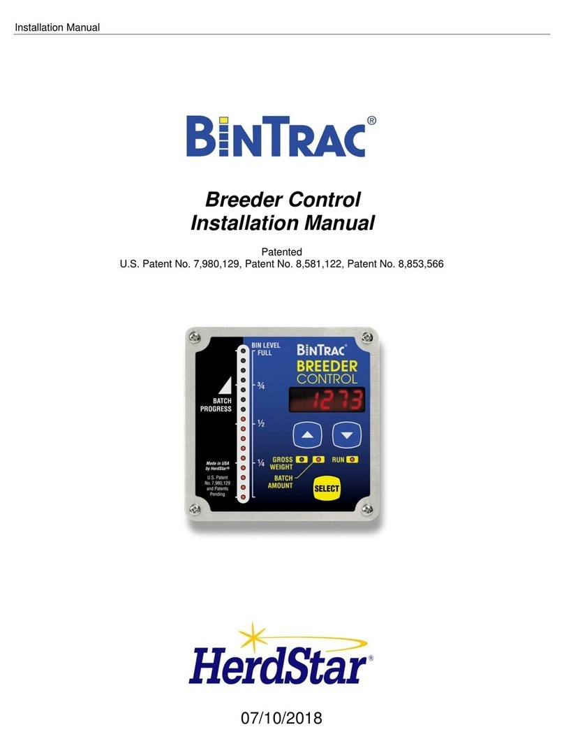
Breeder Control
Operation Manual
Patented
U.S. Patent No. 7,980,129 and Patents Pending

Operation Manual
BinTrac Breeder Control Operation Manual Ver. 1.01 Rev 1.04 2 Part # MAN-000008
1400 Madison Avenue / Suite 504 / Mankato, MN 56001
PH: 507-344-8005 FAX: 507-344-8009
www.herdstar.com
Table of Contents
Overview.............................................................................................................................................................................3
Components...................................................................................................................................................................3
Features .........................................................................................................................................................................3
Weight Display...........................................................................................................................................................3
Batch Run ..................................................................................................................................................................3
Fill Events...................................................................................................................................................................3
24hr Usage.................................................................................................................................................................3
Remote Display..........................................................................................................................................................3
System Setup .....................................................................................................................................................................4
Operation Settings..........................................................................................................................................................4
Selecting Batching Method ........................................................................................................................................4
Calibrate Bin Empty (Zero) ........................................................................................................................................4
System Settings .............................................................................................................................................................5
Accessing the Setup mode........................................................................................................................................5
Navigating Setup mode..............................................................................................................................................5
Selecting an Option in Setup mode ...........................................................................................................................5
Options in Setup Mode ..............................................................................................................................................6
Setup (Version 1.0 and higher)................................................................................................................................6
Serial Data Command Set.......................................................................................................................................6
Batch........................................................................................................................................................................7
Rated .......................................................................................................................................................................7
Capacity...................................................................................................................................................................7
Increment Value.......................................................................................................................................................8
Full Value.................................................................................................................................................................8
Zero Value ...............................................................................................................................................................8
Year .........................................................................................................................................................................9
Month.......................................................................................................................................................................9
Date .........................................................................................................................................................................9
Hour.........................................................................................................................................................................9
Minute......................................................................................................................................................................9
Station ID Value.......................................................................................................................................................9
Software Version (Version 1.0 and higher)............................................................................................................10
Smart Summing Box Software Version (Version 3.0 and higher) .........................................................................10
End.........................................................................................................................................................................10
Operation..........................................................................................................................................................................11
Select Weight Display ..................................................................................................................................................11
Manual Batch Run........................................................................................................................................................11
Scheduled Batch Run...................................................................................................................................................11
Paused Batch Run .......................................................................................................................................................12
Fill Event During Batch Run.........................................................................................................................................12
Display Fill Events........................................................................................................................................................12
Display 24 Hour Usage ................................................................................................................................................12
Service..............................................................................................................................................................................13
Cleaning.................................................................................................................................................................13
Servicing and Repair .............................................................................................................................................13
Troubleshooting............................................................................................................................................................13
is a trademark of HerdStar, LLC.
Copyright © 2011 Herdstar, LLC. All rights reserved.
Printed in the USA

Operation Manual
BinTrac Breeder Control Operation Manual Ver. 1.01 Rev 1.04 3 Part # MAN-000008
Thank you for purchasing a BinTrac Breeder Control from Herdstar, LLC.
Overview
Your BinTrac Breeder Control provides a cost effective way to automatically monitor bin level and batch a programmed
load or unload amount.
Components
A BinTrac Breeder Control consists of four basic components:
BinTrac Breeder Control
This is the main unit of the BinTrac system. The BinTrac Breeder Control communicates
with the Smart Summing Boxes to register the weight of material in the bins. The material
level is computed and displayed on the LED bar graph.
Load Cell Bracket
Four or more loadcell brackets allow the BinTrac to accurately measure the material weight in your bins. The Smart
Summing Box averages the signals from all brackets to minimize errors that could result from voids (holes) in the
material.
Smart Summing Box
A single Smart Summing Box per bin communicates the current reading on the leg brackets to the Bintrac Breeder
Control.
BinTrac Power Supply
This provides the power for the BinTrac Breeder Control. The power supply converts the line voltage to low voltage.
Features
Weight Display
The Bintrac Breeder Control displays the gross weight of the bin and its level.
Batch Run
The Bintrac Breeder Control features a relay to enable a load or unload system for batching a programmed amount.
Fill Events
The Bintrac Breeder Control records the net weight increase of the last four fill events for each enabled bin.
24hr Usage
The Bintrac Breeder Control records the last four operational 24 hour usage amounts.
Remote Display
A Bintrac Breeder Control can be configured as a Remote Display which will display the same updated weight
information from the host BinTrac Indicator.

Operation Manual
BinTrac Breeder Control Operation Manual Ver. 1.01 Rev 1.04 4 Part # MAN-000008
System Setup
The units are easily wired by a qualified technician using standard communication wiring. See Appendix A and
Appendix B drawings for detailed load and unload wiring information. The System setup has two levels of settings: 1)
Operation Settings: These are settings that may be changed for normal use by an operator and 2) System Settings:
These are a one-time setup usually done at the time of installation.
Operation Settings
New BinTrac Breeder Control installations require a one-time system configuration procedure before use. In this mode
you can configure the batching method you wish to use.
Selecting Batching Method
This procedure will allow you to select the batching method you wish to use. On the BinTrac
Indicator, press and hold the SELECT key for approximately 8-10 seconds. The bin level gauge
will go blank, and all of the bin selector indicators will illuminate showing their current status.
1. Press the SELECT key to select the desired bin.
2. Press the key to proceed. The indicator for bin “A” will remain on, and all others will turn off. If the indicator
is on steady, “A” bin is being monitored. If it is flashing, the bin is not being monitored. Press the or
key to toggle bin monitoring on or off.
3. Repeat steps 2-3 for additional bins.
4. Unit returns to Weight Display mode after this procedure or after 20 seconds of no activity (no keystrokes).
Calibrate Bin Empty (Zero)
This procedure will zero the BinTrac weight by correcting for the dead-load of the empty bin.
1. Press the SELECT key to select desired Bin.
2. Press the and then the key and hold for 5 seconds. While held, the bar graph and bin indicators will
flash until 5 seconds have passed and the indicated bin level has been zeroed.
3. Unit returns to Weight Display mode after this procedure or after 20 seconds of no activity (no keystrokes).

Operation Manual
BinTrac Breeder Control Operation Manual Ver. 1.01 Rev 1.04 5 Part # MAN-000008
SEtUP
Figure 1
System Settings
The setup mode is used to configure the one-time system setup settings for each bin.
If there is no activity for 20 seconds while in SETUP mode, the system will exit SETUP mode and return to Weight
Display mode.
Accessing the Setup mode
This menu can be accessed with two methods:
1. This method requires you to power the device down and wait at least 3 seconds before
re-applying power to the system. When the device is powered up it will automatically
enter SETUP mode and display the Ver.
2. This method requires you to hold the SELECT button down for approximately
10 seconds, at which time SETUP mode will be displayed.
Segmented display:
Navigating Setup mode
To navigate through the options in Setup mode, you can use the and the keys to cycle
through the options/parameters. See Figure 1 for the SETUP menu flow chart.
Selecting an Option in Setup mode
To select an option/parameter to edit in SETUP mode, you must navigate to the option
you wish to edit. Navigate using the and keys, and then pressing the SELECT key
when you reach the desired option.
SETUP
Batch
Rated
Capacity
Increment
Full
Zero
Year
Month
Date
Hour
Minute
Station ID
Ver
SS.Ver
End

Operation Manual
BinTrac Breeder Control Operation Manual Ver. 1.01 Rev 1.04 6 Part # MAN-000008
Options in Setup Mode
Setup (Version 1.0 and higher)
The LEDs indicate various configuration options as being enabled (solid on) or disabled (flashing). When
SETUP is displayed on the screen, the following LED’s are used to configure the functionality as noted below.
Gross Weight –Configures BinTrac Indicator as a Remote Display.
A Remote Display is hardwired to a BinTrac Indicator for remotely viewing weight data.
Batch Amount –Enable ASCII Serial Communications Command Set. (See Below)
BinTrac Monitor or BinTrac Remote Display will transmit weight data based on received commands.
Enable this feature when interfacing unit to a PC or serial type device.
Flashing Light –Enable Weight Broadcast
ASCII weight data will be serially broadcast approximately once ever second.
RUN –Enable communications to peripheral devices.
Must be enabled when BinTrac Monitor is connected to BinTrac Remote Display
or HouseLink Interface.
1. Press the SELECT key to select the desired configuration option.
2. Use the or keys to enable or disable options.
Segmented display:
Serial Data Command Set
Poll
Command
Description and
Data Record Format ( fixed length )
P
Current weight of first enabled bin
+/-wwwwwcrlf
PP
Current weight of all four bins
+/-wwwww,+/-wwwww,+/-wwwww,+/-wwwwwcrlf
SnnP
Current weight of first enabled bin with matching BinTrac Station ID
+/-wwwwwcrlf
SnnPP crlf
Current weight of all four bins with matching BinTrac Station ID
+/-wwwww,+/-wwwww,+/-wwwww,+/-wwwwwcrlf
Note: All commands must be terminated by CR. Latency between characters within a multiple
character command (including CR), cannot exceed 200msec.
w –Bin Weight
n –Station ID Number
CR –Carriage Return (Hx0D).
LF –Line Feed (Hx0A).
SEtup

Operation Manual
BinTrac Breeder Control Operation Manual Ver. 1.01 Rev 1.04 7 Part # MAN-000008
Batch
Enables you to set the batch option from LoAd to u.LoAd. LoAd is used when you want material batched into a bin.
Based on the gross weight of the bin, material is batched into the bin until the batched amount equals the gross
amount. u.LoAd is used when you want material batched out of a bin. In this case, the bin is holding a bulk amount of
feed and will batch out the programmed batch amount.
1. Press the SELECT key to enter menu.
2. Use the or keys to select Load or uLoad.
Segmented display:
Rated
The average rated output, in millivolt/volt of the load cells. DO NOT CHANGE unless necessary. Every standard load
cell has a rated output, specified in mV/V. If using load cells other than the Herdstar load cells, adjust this value
appropriately.
1. Press the SELECT key to select the desired Bin.
2. Use the key to increase the rated output by 0.001.
3. Use the key to decrease the rated output by 0.001.
Segmented display:
Capacity
Sets the system capacity of each bin. The system capacity is the sum of all the load cells rated capacity. When
setting for kilograms, convert the total system capacity to kilograms.
Ex: Six leg bin with six 10k loadcells, capacity setting for pounds is 60,000. Capacity setting for kilograms is
27,215. 1. Press the SELECT key to select the desired Bin.
2. Use the key to increase the value by 1 unit.
3. Use the key to decrease the value by 1 unit.
Segmented Display:
rAtEd
cAP
BAtch
Atch

Operation Manual
BinTrac Breeder Control Operation Manual Ver. 1.01 Rev 1.04 8 Part # MAN-000008
200.
100.
50.
…..
10.
5.
2.
1.
500.
Increment Value
Sets the increment that the bin weight will display at. The reading from a bin is
rounded to the nearest multiple of the increment, using standard rounding rules.
The possible values are: 1, 2, 5, 10, 20, 50, 100, 200, 500, 1., 2.,5.,10.,20.,50..
See figure 2.
** Example: If an increment of 10 is selected and the net value of a bin’s weight is
18,582 lbs.; the segmented display will read 18580.
Note: When the increment number is followed by a “.” the displayed weight
value is then scaled by 10. (120462 is displayed as 12046.) This is required
when the displayed weight will exceed five digits.
1. Press the SELECT key to select the desired bin.
2. Use the key to increase the value to the nearest 10 units.
3. Use the key to decrease the value to the nearest 10 units.
Segmented display:
Figure 2
Full Value
Sets the maximum weight of a full bin either in pounds or kilograms. It is how much material the bin can hold. This is
for calibration of the LED bar graph level. The value says at what net weight the bar graph will display completely full
(all 16 LEDs lit).
1. Press the SELECT key to select the desired Bin.
2. Use the key to increase the value by 1 unit.
3. Use the key to decrease the value by 1 unit.
Segmented display:
Zero Value
Sets the weight of the empty bin either in pounds or kilograms. This value can also be set in the Operation Settings.
This is used to compensate for the empty weight of the bin to give an accurate value for the net weight of the material
inside the bin. ** Example: A bin weighs 1,200 lbs. empty. This is then set to the zero value: the BinTrac then
calculates the material weight as the total weight less the zero weight value.
1. Press the SELECT key to select the desired Bin.
2. Use the key to increase the value by 1 unit.
3. Use the key to decrease the value by 1 unit.
Segmented display:
fULL
ZEro
inc

Operation Manual
BinTrac Breeder Control Operation Manual Ver. 1.01 Rev 1.04 9 Part # MAN-000008
Year
Sets the current Year.
Segmented display:
Month
Sets the current Month.
Segmented display:
Date
Sets the current Date.
Segmented display:
Hour
Sets the current Hour.
Segmented display:
Minute
Sets the current Minute.
Segmented display:
Station ID Value
Sets the Station ID of the device. For devices interfacing with a Site Console, the Station ID must be set within 100 –
131. When interfacing the device to a Communication Hub (CH100), set this value between 1and 99. Each BinTrac
device must have a unique Station ID.
1. Press the SELECT key to select the desired Bin.
2. Use the key to increase the value by 1.
3. Use the key to decrease the value by 1.
Segmented display:
id
yEAr
nnon
dAtE
Hour
nnin

Operation Manual
BinTrac Breeder Control Operation Manual Ver. 1.01 Rev 1.04 10 Part # MAN-000008
Software Version (Version 1.0 and higher)
Displays the BinTrac programmed software version number. This number may be required if technical help is needed.
1. Press the SELECT key to see the software version number.
Segmented display:
Smart Summing Box Software Version (Version 3.0 and higher)
Displays each of the connected Smart Summing Boxes programmed software version number. This number may be
required if technical help is needed.
1. Press the BIN key to see the software version for each enabled bin.
Segmented display:
End
Allows the user to exit SETUP mode.
1. Press the SELECT button to exit SETUP mode.
Segmented display:
End
UEr
SS.UEr

Operation Manual
BinTrac Breeder Control Operation Manual Ver. 1.01 Rev 1.04 11 Part # MAN-000008
Operation
Select Weight Display
Press the SELECT key to select between Gross weight and Batch amount. The Gross Weight
is the total material remaining in the bin. The bar graph indicates the approximate level of the
bin. The Batch amount is remaining weight left to batch to reach the Batch Target. Note: Batch
Weight always starts at the Batch Target and counts down to “0” weight. This provides the best
means to display the amount left to batch.
Manual Batch Run
1. Press key until “bAtch”is displayed.
2. Press SELECT to view the Batch Target Weight value.
3. Use the key to increase the value by 1.
4. Use the key to decrease the value by 1
5. Press SELECT to display the batch run control status ( “run” or “Stop” )
6. Use the or keys to enable or disable batch run control.
7. Press SELECT to start Batching if run was selected. The batch run will begin immediately.
Scheduled Batch Run
1. Press key until “bAtch”is displayed.
2. Use the key to select “SchdL”.
3. Use the key to select hour and minute to schedule batch.
Note: This is a 24 hour clock. ie. 13:00 = 1:00 p.m.
4. Press SELECT to view the Batch Target Weight value.
5. Use the key to increase the value by 1.
6. Use the key to decrease the value by 1
7. Press SELECT to display the batch run control status ( “run” or “Stop” )
8. Use the or keys to enable or disable batch run control.
9. Press SELECT with “run” displayed. The Indicator will then display the batch amount and a countdown to the
next batch run.
10. To stop a scheduled batch run use the key and “StOP” will be displayed. Press the SELECT key once to
stop and again on the batch amount. The Indicator will then return to display the gross amount in the bin.

Operation Manual
BinTrac Breeder Control Operation Manual Ver. 1.01 Rev 1.04 12 Part # MAN-000008
Paused Batch Run
1. To pause a batch in mid run, press the key until “PAUSE” is displayed. Press SELECT key to pause the
batch run.
2. When paused, the indicator will display “PAUSE” and the remaining batch amount on the screen.
3. To restart the batch, press the key until “run” is displayed then press the SELECT key. The batch will then
continue until completed.
Fill Event During Batch Run
1. If a FILL event occurs just prior to a batch being enabled, the unit will switch to FILL batching mode until FILL
event has completed. The unit will remain in FILL batching mode for 20 minutes after the FILL event is
complete to calibrate the additional weight.
2. If this occurs during the time when a scheduled batch run is set to go, the scheduled batch run will be skipped.
A manual batch run can be done at this time.
3. If a FILL event occurs while a batch is running and the weight increases by 50 lbs. or more in the bin, the
BinTrac WBBS will pause the batch and switch to FILL batching mode until FILL is completed.
4. The unit will remain in FILL batching mode for 20 minutes after the FILL event is complete to calibrate the
additional weight and then resume batching the remaining amount.
Display Fill Events
This procedure allows you to view the last four recorded fill events.
5. Press the key until “Fill” is displayed.
6. Press SELECT to view the last recorded fill event.
7. Press key to view other prior recorded fill events.
8. Press SELECT to return to Weight Display mode or unit will return to Weight Display mode after 20 seconds of
no activity (no key strokes).
Display 24 Hour Usage
This procedure allows you to view the last four 24 hour usage amounts.
1. Press the key twice until “usage” is displayed.
2. Press SELECT to view the last recorded 24 hour usage amount.
3. Press key to view other prior recorded usage amounts.
4. Press SELECT to return to Weight Display mode or unit will return to Weight Display mode after 20 seconds of
no activity (no key strokes).

Operation Manual
BinTrac Breeder Control Operation Manual Ver. 1.01 Rev 1.04 13 Part # MAN-000008
Service
Cleaning
Do not clean the BinTrac modules with a pressure washer. Use a washcloth soaked in warm water containing a mild
detergent and disinfectant.
Servicing and Repair
Your BinTrac module contains NO USER SERVICEABLE PARTS. If the product stops working for any reason, it must
be returned for repair.
Troubleshooting
There are a few types of errors that can be encountered during operation of the BinTrac. The following should give
you some insight into the cause of the error should one occur. Errors displayed are specific to the selected bin.
Error -If this is displayed on the screen, the BinTrac is unable to display the current value or the value is
outside the displayable range. Verify programmed settings are correct including zero or check for faulty
loadcell.
no.bin -This means that the Smart Summing Box for the selected bin is not communicating. Check for broken
wires or loose connections, or Smart Summing Box is not correctly configured, or faulty loadcell. Inspect Smart
Summing Box internal diagnostic light; 1)flashing regular –normal working condition, 2)off –no power
indication, 3)flashing irregular - unable to communicate.
oLOAd -This means that the weight in the bin has exceeded the programmed system capacity by 150% and
the system is in an over-load state. Remove the weight from the system and check the condition of each load
cell.
no.con - This means that the Remote Display has lost communications with the host BinTrac Monitor. Check
for broken wires or loose connections and verify unit was intended for use as a Remote Display and not
accidentally misprogrammed.
no.PuL -This error message indicates that the BinTrac Indicator has been programmed for a PULSE output
and is unable to communicate with the HouseLink WP. If not connected to a HouseLink WP, set Pulse weight
to “0”.
Error
nobin
oL0Ad
No.con
No.Pul

Operation Manual
BinTrac Breeder Control Operation Manual Ver. 1.01 Rev 1.04 14 Part # MAN-000008
Herdstar Bintrac® Product Warranty
Herdstar LLC. (“Herdstar”) warrants to original purchaser (“Buyer”) that goods manufactured solely by Herdstar LLC.
(“Products”) will be free from defects in material or workmanship under normal and intended use and service for a
period of one year from delivery date of the Products. Used and/or refurbished parts sold shall carry a 90 day warranty
on material and workmanship. All warranty claims must be submitted within ten (10) days of discovery of defects within
the warranty period, or shall be deemed waived. Furthermore, Herdstar LLC warrants the load cell (“Load cell” is
defined as the s-shaped component and any cabling and connectors) against lightning damage for 12 months or the
term of any extended warranty.
In the event of a defect in any Products constituting a breach of the warranty provided herein, Herdstar LLC. will at its
option either (i) repair or replace such Product free of charge, or (ii) in lieu of repair or replacement, refund to Buyer the
original purchase price less the reasonable value of Buyer’s use of the Products. Herdstar LLC. shall furnish to Buyer
instructions for the disposition of the defective goods. Herdstar LLC shall have the option of requiring the return of the
defective goods, transportation prepaid, and proof that the goods were not used, installed or altered or subject to
misuse or abuse to establish the claim. No goods shall be returned to Herdstar LLC. without its prior consent. The
acceptance of any goods returned to Herdstar LLC shall not be deemed an admission that the goods are defective or
in breach of any warranty, and if Herdstar LLC determines that the goods are not defective they may be returned to
Buyer at Buyer’s expense. This warranty sets forth Buyer’s sole and exclusive remedies for any defect in the goods.
The rights and obligation under this warranty may not be assigned or delegated to a third party by Buyer without the
prior written permission of Herdstar LLC. Neither Buyer nor any other person may modify or expand the warranty
provided herein, waive any of the limitations, or make any different or additional warranties with respect to the
Products. Any statements to the contrary are hereby rendered null and void unless expressly agreed to in writing by an
authorized officer of Herdstar LLC.
EXCEPT AS STATED IN ABOVE, HERDSTAR LLC DOES NOT MAKE ANY WARRANTY AS TO THE GOODS OR
SERVICES AND, IN PARTICULAR, DOES NOT MAKE ANY WARRANTY OF MERCHANTABILITY OR FITNESS
FOR ANY PARTICULAR PURPOSE, AND BUYER IS SOLELY RESPONSIBLE FOR DETERMINING THE PROPER
APPLICATION AND USE OF THE GOODS.
Herdstar LLC makes no representation or warranty that individual animals, or any given population of animals, will
utilize any of Herdstar LLC.’s goods in the manner for which the goods were intended or designated. Any component
parts that are not manufactured by Herdstar LLC., such as electrical motors and controls, are excluded from any
warrant by Herdstar LLC., although such parts may be covered by separate warranties of the respective
manufacturers. This warranty set forth above does not apply if all components of a system are not supplied by Herdstar
LLC. or if the goods are not purchased from and installed by an authorized distributor or company warehouse, or
installed and operated in accordance with Herdstar LLC.’s specifications and instructions.
HERDSTAR LLC SHALL NOT HAVE ANY TORT LIABILITY TO BUYER OR ANY OTHER PERSON WITH RESPECT
TO ANY OF THE GOODS OR SERVICES AND SHALL NOT BE LIABLE FOR CONSEQUENTIAL, INCIDENTAL,
SPECIAL, EXEMPLARY, INDIRECT OR PUNITIVE DAMAGES ARISING FROM ANY PRODUCT DEFECT, DELAY,
NONDELIVERY, RECALL OR OTHER BREACH. BUYER SHALL NOT HAVE ANY RIGHT OF REJECTION OR OF
REVOCATION OF ACCEPTANCE OF THE GOODS.
Other manuals for Bintrac
3
Table of contents
Other herdstar Controllers manuals
