herdstar Bintrac User manual

High Capacity Pancake
Load Cell Installation Guide
Version 1.10
07/18/19
is a registered trademark of Herdstar, LLC.
Copyright © 2016 Herdstar, LLC. All rights reserved.
Printed in the USA
1400 Madison Avenue /Suite 504 / Mankato, MN 56001
PH: 507-344-8005 FAX: 507-344-8009
www.herdstar.com
Installation Manual
2
Version 1.10 07/18/2019
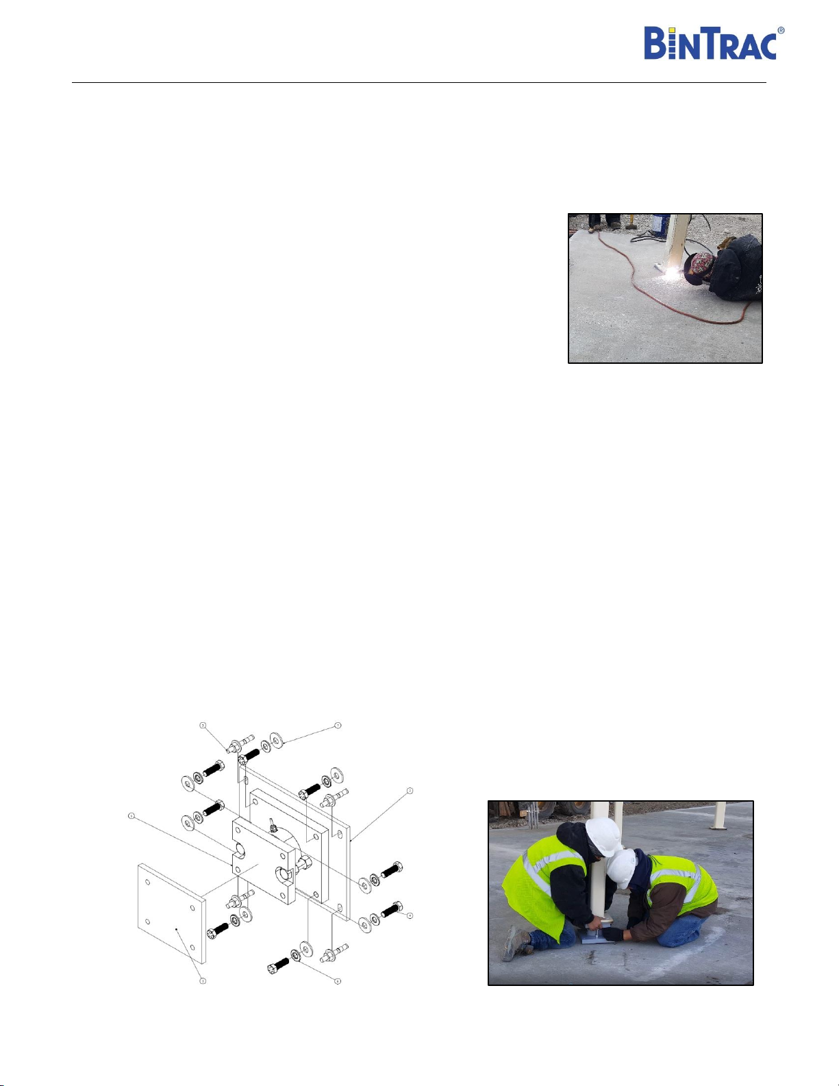
Installation Instructions
Step 1:
Attach the Weld Plate adapter to the bottom of the bin legs
1. Raise the bin and carefully center the grey weld plate adapter onto the proper
position. (Bin legs are typically a beam, I-beam or right-angle style configuration.
Reference Figures 7-8 for dimensional drawings)
2. There are three versions of the pancake assemblies available:
•Standard Assembly (No weld plate adapter or anchor plate)
•Assembly with Weld Plate adapter (No anchor plate)
•Assembly with Weld Plate adapter and Anchor plate (shown on pages 5-6)
3. Weld the plate adapter onto the bottom leg plate, tube leg in some cases).
WARNING: DO NOT WELD TO ADAPTER PLATE WITH THE ENTIRE LOAD
CELL ASSEMBLY, AS IT IS POSSIBLE TO DAMAGE THE LOAD CELL.
Step 2:
Position/Attach the Main Pancake Loadcell assembly underneath each bin leg
1. If using the optional black anchor base plate, make sure it has been installed and hand tightened to the lower pancake plate
using 4 pcs of the 5/8 in. x 2 in. bolts with 5/8 washer and lock washers. (See figure 2 below). The black anchor plate is
optional but recommended as it makes removal of the entire load cell bracket assembly in the future very convenient if
needing to be replaced.
2. Slowly raise the entire bin a minimum of 5.5 inches to allow positioning the pancake assemblies underneath each bin leg.
Then after the bin is in position slide the load cell assembly underneath the legs. Carefully align the weld plate and bolt
upwards from the pancake cell upper plate to the bottom side of the bin legs weld plate. Assemble using 4 pcs of the 5/8 in x
2in. bolts, along with the 5/8 washer and lock washers (See Figure 2 below). The hardware can be hand tightened initially
until the bin is lowered and in final position.
3. Once the loadcell assembly is attached to the leg, carefully lower the bin and place into the final location.
Figure 2

Installation Manual
3
Version 1.10 07/18/2019
Step 3:
Install Anchor bolts and attach bin to concrete
1. Drill four anchor bolt holes 2 ¼” deep in the concrete pad through the outside oval
slots in the corners of the black anchor plate. Hammer the anchor bolts into concrete
until they are firmly in place. Tighten the nuts of the anchor bolts using a socket or
hammer drill to anchor the bracket assembly. Torque to 55 ft-lb.
2. Now the bin is in the proper position, tighten the four bolts attached to the weld plate
adapter. Finally loosen the two top nuts on the two side bolts going from the top to
the bottom plate. WARNING: THE TWO NUTS MUST BE LOOSENED OR THE WEIGHING
SYSTEM WILL NOT WEIGH PROPERLY. RECOMMEND LOWERING THE NUTS A ½ INCH
TO REASSURE IT IS NO LONGER SUPPORTING THE TOP PLATE. (SEE FIGURE 3).
3. Then secure and firmly tighten all the anchor base plate nuts and the four bolts
attached to the weld plate adapter for each of the legs.
Step 4:
Wiring the Summing Box
1. Mount the Smart Summing Box (SSB) on the crossbar under the bin near the front using self -tapping screws where it is easily
accessible for maintenance.
2. Remove the plated connector cover on the side of the pancake assembly, and screw in the interface cable tightly. Avoid getting
moisture in the connector on the pancake cell or the end of the cable while installing the load cells. Once connected to the
pancake load cell run the cable from each load cell over to the summing box.
3. Before plugging the cables in, remove the black plastic lock nut from each cable strain
relief. Remove the red plug from each predrilled hole. Pass the cable through the box
and then the nut.
4. Plug in the load cells starting in the upper left until all load cells are plugged in.
5. Pass the communication cable through the gray liquid tight strain
relief on the right side of the enclosure.
6. Using an appropriate size wire nut, connect the wires as shown (Figure 4).
7. Attach the GREEN ground wire to the bin using a self-tapping screw.
8. Run the communication wire to the next SSB or to the BinTrac® Indicator.
Tighten every strain-relief (“dome nuts”) on the box. First tighten the
nuts to attach the strain reliefs to the box. Then tighten the dome nut until
the cable cannot be pulled out of the box.
9. Set the appropriate bin (A,B,C,D) using the dip switches inside the summing
Box (Figure 5)
Figure 3
BIN S1 S2 S3 S4
AOFF OFF OFF OFF
BON OFF OFF OFF
COFF ON OFF OFF
DON ON OFF OFF
Figure 5
Figure 4

Installation Manual
4
Version 1.10 07/18/2019
Step 5:
Wiring the BinTrac Power Supply
1. The PS17 Power Supply is intended for INDOOR USE ONLY and should be mounted in an office, building or hallway close to
power outlet.
2. Mount the Power Supply appropriately in a location that allows the cable to be tied to the feed line, or other structure
preventing entanglement by a person walking between the bin and the building.
3. Once the cable is routed from the Power Supply to the BinTrac® Indicator and has been tied up out of the way, cut off any
excess cable and connect to the BinTrac® Indicator.
Step 6:
Wiring the BinTrac BT260 Indicator
1. Locate the terminal block in the BinTrac® Indicator labeled ‘BINS’.
2. Insert the wires into the terminal block where RED is +12V OUT, GREEN
is +COM IN, WHITE is –COM IN and BLACK is -12V OUT. (Figure 6)
3. Connect the wires from the BinTrac® power supply to the terminal
block labeled ‘12V IN’ where WHITE is +12V and BLACK is -12V.
Step 7:
Setting up the BinTrac Indicator
1. Press and hold the BIN key until SETUP appears, release and “bin” appears.
2. Press BIN key to go to ‘A’. Press DOWN arrow to enable (solid light) or disable (flashing light) the bins. Use the same procedure
to enable/disable bins B, C or D depending upon your configuration.
3. Once the bins are configured, use the DOWN arrow to go to
‘L.C. CAP’. The amount is the load cell capacity x # of bin legs. Press bin key to modify the first enabled bin. Use the UP or
DOWN arrows to change the weight until set properly. Use the same procedure for the remaining active bins.
EXAMPLE: A 6 legged bin with 25k pancake load cells equals 150,000.
4. Next, use the DOWN arrow to go to ‘FULL’.
5. Press bin key to modify the first enabled bin. The ‘FULL’ number is the bin capacity. Use the UP or DOWN arrows to change the
weight until set properly. Use the same procedure for the remaining active bins.
EXAMPLE: a 50 ton bin will have a ‘FULL’ number of 100,000.
6. If the bin is empty, exit the setup menu and press and hold the DOWN arrow and the UP arrow until the bin reads ‘0’.
Note: The settings above are in lb, but can be changed to kg by entering the metric value. EXAMPLE: 60,000 lbs. = 27,216 kg.
TROUBLESHOOTING
1. no.bin - The Smart Summing Box for the selected bin is not communicating. Verify wiring is correct and there is power to the
unit. Inspect Smart Summing Box internal diagnostic light; 1) flashing regular: normal working condition, 2) off: no power
indication, 3) flashing irregular: unable to communicate.
2. no.con –This error message indicates the BinTrac Indicator has been programmed as a Remote Display. Consult the BinTrac
Operation Manual on procedure to change or configure.
3. oLOAd -The weight in the bin has exceeded the programmed system capacity by 150% and the system is in an over-load state.
Verify capacity settings.
4. Error –The BinTrac Indicator is unable to display the current weight value or the value is outside the displayable range. Verify
programmed settings are correct including zero or check for faulty load cell.
Figure 6

Installation Manual
5
Version 1.10 07/18/2019
25 K Pancake Assembly Outline Dimensions
Figure 7

Installation Manual
6
Version 1.10 07/18/2019
55 K Pancake Assembly Outline Dimensions
Figure 8

Installation Manual
7
Version 1.10 07/18/2019
Herdstar BinTrac® Product Warranty
Herdstar LLC. (“Herdstar”) warrants to original purchaser (“Buyer”) that goods manufactured solely by Herdstar
LLC. (“Products”) will be free from defects in material or workmanship under normal and intended use and service
for a period of one year from delivery date of the Products. Used and/or refurbished parts sold shall carry a 90 day
warranty on material and workmanship. All warranty claims must be submitted within ten (10) days of discovery of
defects within the warranty period, or shall be deemed waived. Furthermore, Herdstar LLC warrants the load cell
(“Load cell” is defined as the s-shaped component and any cabling and connectors) against lightning damage for
12 months or the term of any extended warranty.
In the event of a defect in any Products constituting a breach of the warranty provided herein, Herdstar LLC. will at
its option either (i) repair or replace such Product free of charge, or (ii) in lieu of repair or replacement, refund to
Buyer the original purchase price less the reasonable value of Buyer’s use of the Products. Herdstar LLC. shall
furnish to Buyer instructions for the disposition of the defective goods. Herdstar LLC shall have the option of
requiring the return of the defective goods, transportation prepaid, and proof that the goods were not used, installed
or altered or subject to misuse or abuse to establish the claim. No goods shall be returned to Herdstar LLC. without
its prior consent. The acceptance of any goods returned to Herdstar LLC shall not be deemed an admission that
the goods are defective or in breach of any warranty, and if Herdstar LLC determines that the goods are not
defective they may be returned to Buyer at Buyer’s expense. This warranty sets forth Buyer’s sole and exclusive
remedies for any defect in the goods. The rights and obligation under this warranty may not be assigned or
delegated to a third party by Buyer without the prior written permission of Herdstar LLC. Neither Buyer nor any other
person may modify or expand the warranty provided herein, waive any of the limitations, or make any different or
additional warranties with respect to the Products. Any statements to the contrary are hereby rendered null and
void unless expressly agreed to in writing by an authorized officer of Herdstar LLC.
EXCEPT AS STATED IN ABOVE, HERDSTAR LLC DOES NOT MAKE ANY WARRANTY AS TO THE GOODS
OR SERVICES AND, IN PARTICULAR, DOES NOT MAKE ANY WARRANTY OF MERCHANTABILITY OR
FITNESS FOR ANY PARTICULAR PURPOSE, AND BUYER IS SOLELY RESPONSIBLE FOR DETERMINING
THE PROPER APPLICATION AND USE OF THE GOODS.
Herdstar LLC makes no representation or warranty that individual animals, or any given population of animals, will
utilize any of Herdstar LLC.’s goods in the manner for which the goods were intended or designated. Any component
parts that are not manufactured by Herdstar LLC., such as electrical motors and controls, are excluded from any
warrant by Herdstar LLC., although such parts may be covered by separate warranties of the respective
manufacturers. This warranty set forth above does not apply if all components of a system are not supplied by
Herdstar LLC. or if the goods are not purchased from and installed by an authorized distributor or company
warehouse, or installed and operated in accordance with Herdstar LLC.’s specifications and instructions.
HERDSTAR LLC SHALL NOT HAVE ANY TORT LIABILITY TO BUYER OR ANY OTHER PERSON WITH
RESPECT TO ANY OF THE GOODS OR SERVICES AND SHALL NOT BE LIABLE FOR CONSEQUENTIAL,
INCIDENTAL, SPECIAL, EXEMPLARY, INDIRECT OR PUNITIVE DAMAGES ARISING FROM ANY PRODUCT
DEFECT, DELAY, NONDELIVERY, RECALL OR OTHER BREACH. BUYER SHALL NOT HAVE ANY RIGHT OF
REJECTION OR OF REVOCATION OF ACCEPTANCE OF THE GOODS.
Other manuals for Bintrac
3
Table of contents
Popular Welding System manuals by other brands


MK Products
MK Products CobraTig 150 SM 254-153 owner's manual

Miller Electric
Miller Electric XMT 350 CC/CV Brochure & specs

Lincoln Electric
Lincoln Electric FineLine 300HD Operator's manual

EWM
EWM Tetrix 300 DC Smart 2.0 puls manual

Lincoln Electric
Lincoln Electric COOLARC-45 Operator's manual

Paton
Paton PRO-160 user manual

Lincoln Electric
Lincoln Electric DC-655 IM602-A Operator's manual

GYS
GYS MULTIWELD 250T manual

Century
Century INVERTER ARC 120 Operator's manual

Campbell Hausfeld
Campbell Hausfeld WG2020 Operating instructions and parts manual

Lincoln Electric
Lincoln Electric NA-5 IM305-C Operator's manual

Scheppach
Scheppach WSE850 instruction manual