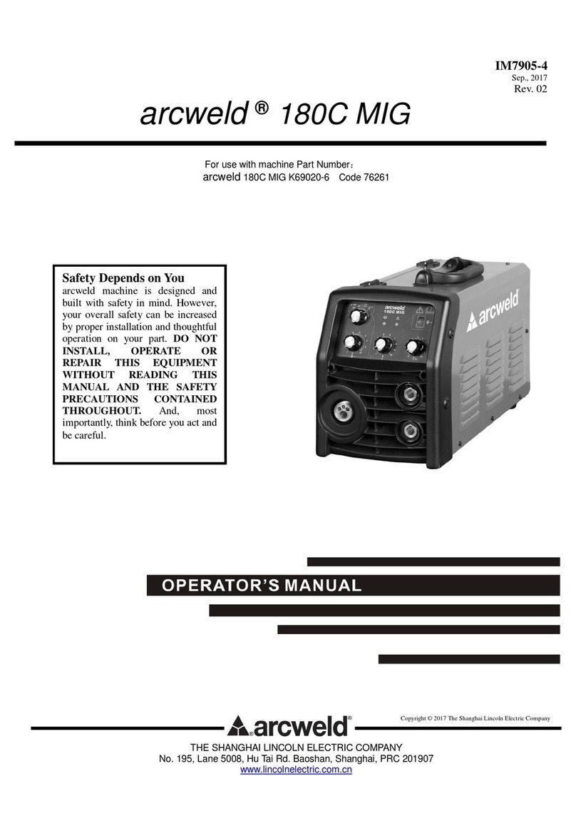
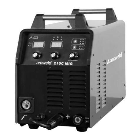
arcweld TIG 205 DC User manual

IM7907-5
Apirl. 2015
Rev. 01
arcweld®TIG 205 DC
For use with machine Part Number K69029-7, Code 76263
THE SHANGHAI LINCOLN ELECTRIC COMPANY
No. 195, Lane 5008, Hu Tai Rd. Baoshan, Shanghai, PRC 201907
www.lincolnelectric.com.cn
Copyright © 2015 The Shanghai Lincoln Electric Company
Safety Depends on You
arcweld®machine is designed
and built with safety in mind.
However, your overall safety
can be increased by proper
installation and thoughtful
operation on your part. DO NOT
INSTALL, OPERATE OR
REPAIR THIS EQUIPMENT
WITHOUT READING THIS
MANUAL AND THE SAFETY
PRECAUTIONS CONTAINED
THROUGHOUT. And, most
importantly, think before you act
and be careful.

Thank you for selecting QUALITY arcweld®products.
Please examine the packaging and equipment for damage. Claims for material damaged in shipment must be
notified immediately to the authorized dealer from whom you purchased the machine.
For future reference,please record your equipment identification information in the table below. Model Name,
Code & Serial Number can be found on the machine rating plate.
Model Name
□arcweld®TIG 205 DC
Code & Serial number
Date & Where Purchased
Authorized dealer’s shop
Declaration of conformity
THE SHANGHAI LINCOLN ELECTRIC COMPANY
Designed in conformance with the following norm:
AS 60974.1
GB15579.1
IEC 60974-1
THE SHANGHAI LINCOLN ELECTRIC COMPANY
No. 195, Lane 5008, Hu Tai Rd. Baoshan, Shanghai, PRC 201907

iSAFETY i
ARC WELDING CAN BE HAZADOUS. PROTECT YOURSELF AND OTHERS FROM
POSSIBLE SERIOUS INJURY OR DEATH. KEEP CHILDREN AWAY. PACEMAKER
WEARERS SHOULD CONSULT WITH THEIR DOCTOR BEFORE OPERATING.
BE SURE THAT ALL INSTALLATION, OPERATION, MAINTENANCE AND REPAIR
PROCEDURES ARE PERFORMED ONLY BY QUALIFIED INDIVIDUALS.
ELECTRIC AND
MAGNETIC FIELDS
may be dangerous.
1.a Electric current flowing through any conductor
causes localized Electric and Magnetic Field
(EMF). Welding current creates EMF fields
around welding cables and welding machines.
1.b EMF fields may interfere with some
pacemakers, and welders having a pacemaker
should consult their physican before welding.
1.c All welders should use the following procedures
in order to minimize exposure to EMF fields
from the welding circuit:
1.d.1 Route the electrode and work cables
together –Secure them with tape when
possible.
1.d.2 Never coil the electrode lead around your
body.
1.d.3 Do not place your body between the
electrode and work cables. If the
electrode cable is on your right side, the
work cable should also be on your right
side.
1.d.4 Connect the work cable to the workpiece
as close as possible to the area being
welded.
ARC RAYS can burn.
2.a Use a shield with the proper filter and cover
plates to protect your eyes from sparks and the
rays of the arc. Headshield and filter lens
should conform to AS 1338.1 standard.
2.b Use suitable clothing made from durable flame-
resistant material to protect your skin and that
of your helpers from the arc rays.
2.c Protect other nearby personnel with suitable,
non-flammable screening and/or warn them not
to watch the arc nor expose themselves to the
arc rays or to hot spatter or metal.
ELECTRIC SHOCK can
kill.
3.a The electrode and work (or ground) circuits are
electrically “hot” when the welder is on. Do not
touch these “hot” parts with your bare skin or wet
clothing. Wear dry, hole-free gloves to insulate
hand.
3.b Insulate yourself from work and ground using dry
insulation. Make certain the insulation is large
enough to cover your full area of physical contact
with work and ground.
In addition to the normal safety precautions, if
welding must be performed under electrically
hazardous conditions (in damp locations or
while wearing wet clothing; on metal structures
such as floors, grating or scaffolds; when in
cramped positions such as sitting, kneeling or
lying, if there is a high risk of unavoidable or
accidental contact with the workpiece or
ground) use the following equipment:
Semiautomatic DC Constant Voltage (Wire)
Welder.
DC Manual (Stick) Welder.
AC Welder with Reduced Voltage Control.
3.c In semiautomatic or automatic wire welding, the
electrode, electrode reel, welding head, nozzle or
semiautomatic welding gun are also electrically
“hot”.
3.d Always be sure the work cable makes a good
electrical connection with the metal being welded.
The connection should be as close as possible to
the area being welded.
3.e Ground the work or metal to be welded to a good
electrical (earth) ground.
3.f Maintain the electrode holder, work clamp, welding
cable and welding machine in good, safe operating
condition. Replace damaged insulation.
3.g Never dip the electrode in water for cooling.
3.h Never simultaneously touch electrically “hot” parts
of electrode holder to two welders because voltage
between the two can be total of the open
circuit voltage of both welders.
WARNING

ii SAFETY ii
FUMES AND GASES
can be dangerous.
4.a Welding may produce fumes and gases
hazardous to health. Avoid breathing these
fumes and gases. When welding, keep your
head out of fume. Use enough ventillation
and/or exhaust at the arc to keep fumes and
gases away from the breathing zone. When
welding with electrodes which require
special ventilation such as stainless or hard
facing (see instructions on container or
MSDS) or on lead or cadmium plated steel
and other metals or coatings which produce
highly toxic fumes, keep exposure as low as
possible and below Threshold Limit Values
(TLV) using local exhaust or mechanical
ventilation. In confined spaces or in some
circumstances, outdoors, a respirator may
be required. Additional precautions are also
required when welding on galvanized steel.
4.b Do not weld in locations near chlorinated
hydrocarbon vapors coming from degreasing,
cleaning or spraying operations. The heat and
rays or the arc can react with solvent vapors to
form phosgene, a highly toxic gas, and other
irritating products.
4.c Shielding gases used for arc welding can
displace air and cause injury or death. Always
use enough ventilation, especially in confined
areas, to insure breathing air is safe.
4.d Read and understand the manufacturer’s
instructions for this equipment and the
consumables to be used, including the material
safety data sheet (MSDS) and follow your
employer’s safety practices. MSDS forms are
available from your welding distributor or from
the manufacturer.
FOR ELECTRICALLY
powered equipment.
5.a Turn off input power using the disconnect
switch at the fuse box before working on the
equipment.
5.b Install equipment in accordance with the
national standard, all local standards and the
manufacturer’s recommendations.
5.c Earth (ground) the equipment in accordance
with the national standards and the
manufacturer’s recommendations.
WELDING SPARKS
can cause fire or
explosion.
6.a Remove fire hazards from the welding area. If this
is not possible, cover them to prevent the welding
sparks from starting a fire. Remember that welding
sparks and hot materials from welding can easily
go through small cracks and openings to adjacent
areas. Avoid welding near hydraulic lines. Have a
fire extinguisher readily available.
6.b When not welding, make certain no part of the
electrode circuit is touching the work or ground.
Accidental contact can cause overheating and
create a fire hazard.
6.c Do not heat, cut or weld tanks, drums or containers
until the proper steps have been taken to insure
that such procedures will not cause flammable or
toxic vapors from subtances inside. They can
cause an explosion even though they have been
“cleaned”.
6.d Sparks and spatter are thrown from the welding
arc. Wear oil free protective garments such as
leather gloves, heavy shirt, cuffless trouses, high
shoes and a cap over your hair.
CYLINDER may
explode if damaged.
7.a Use only compressed gas cylinders containing the
correct shielding gas for the process used and
properly operating regulators designed for the gas
and pressure used. All hoses, fittings, etc. should
be suitable for the application and maintained in
good condition.
7.b Always keep cylinders in an upright position
securely chained to an undercarriage or fixed
support.
7.c Cylinder should be located:
Away from areas where they may be struck or
subjected to physical damage.
A safe distance from arc welding or cutting
operations and any other source of heat,
sparks, or flame.
7.d Never allow the electrode, electrode holder or any
other electrically “hot” parts to touch a cylinder.
7.e Keep your head and face away from the cylinder
valve outlet when opening the cylinder valve.
7.f Valve protection caps should always be in place
and hand tight except when the cylinder is in use
or connected for use.

iii SAFETY iii

iv SAFETY iv

A -1 SUMMARY A-1
64
44
20
0 600 I2(A)
U2(V)
Working
point
Volt-ampere characteristic The relation of the rated
loading voltage&welding
current
64
44
20
0 600 I2(A)
U2(V)
Working
point
Volt-ampere characteristic The relation of the rated
loading voltage&welding
current
VOLT-AMPERE
CHARACTERISTIC
The arcweld®machine has excellent volt-
ampere characteristic, refer to the
following graph. In TIG welding, the
relationship between rated loading voltage
U2and welding current I2 is as follows:
When I2 ≤600A,U2=10+0.04 I2(V);
When I2>600A,U2=34(V)
GENERAL INTRODUCTION
The arcweld®TIG 205 DC is a new generation of multi
functional high quality welding machine. The power
source adopts a microcomputer system control, dual
current loop PWM control, full-bridge high frequency
inverter system. It has convenient operation, stable
performance, small size and high duty cycle. The power
source is mainly applied to the welding of stainless steel,
carbon steel and other metals.
CHARACTERISTICS
To ensure a high success rate of arc starting. The
power source incorporates a high voltage and
pulse(High frequency) arc start circuit but without a
discharge circuit so that it makes arc start easier and
safer. Lift arc start is another option for those wishing
to avoid electromagnetic interference.
Safety, efficiency. From a machine with protection
features such as precharge function, under voltage
protection, over voltage protection, over heat
protection, over current protection and output short
circuit protection. Especially adopted protection
circuit against electric shock: In MMA mode, the
machine will turn off the main loop output power
within 2 seconds after ending welding, the advantage
is safer operation, and saving power.
One machine, 4 types of welding processes:
MMA
DC TIG
DC TIG/PULSE
DC TIG/SPOT
PWM - Pulse-Width Modulation;
MMA - Manual Metal Arc welding;
TIG - Tungsten Inert Gas welding.
68
34
10
0 600 I2(A)
U2(V)
Working
point
Volt-ampere characteristic The relation of the rated
loading voltage&welding
current
STACKING
The arcweld®inverter machine CAN’T be
stacked when welding.
TILTING
Place the machine directly on a secure, level
surface. Do not place or operate the machines
on a surface with an incline greater than 15°
from horizontal. The machine may topple over
if this procedure is not followed.
WELDING CAPABILITY
Please see Technical Specifications in the
Installation Section for rated outputs for the
arcweld®inverter machine. It is capable of
higher duty cycles at lower output currents.
If the duty cycle is exceeded, a thermal
protector will shut off the output until the
machine cools.
A Duty Cycle of 60% example is:
Weld for 6 minutes Break for 4 minutes

B-1 INSTALLATION B-1
TECHNICAL SPECIFICATIONS
INPUT –SINGLE PHASE
Standard Voltage / Phase / Frequency
220V (±10%) / 1 / 50/60 Hz
Rated Max. Input Power
8.1 kW (MMA mode)
6.6 kW (GTAW mode)
Recommended Fuse or Breaker Size (Super Lag or ‘D’ curve)
16A
MMA
Rated Maximum
Supply Current
34 A
Max. Effective
Supply Current
15 A
GTAW
27 A
14 A
RATED OUTPUT –DC ONLY
Welding Mode
Duty Cycle(1)
Amperes
Volts at Rated Amperes
INPUT 1~220V
MMA
20%
60%
100%
170A
98A
76A
26.8V
23.9V
23V
GTAW
25%
60%
100%
200A
129A
100A
18V
15.2V
14V
OUTPUT RANGE
INPUT POWER
Welding Mode
Welding Current
Range
Open Circuit
Voltage
Welding Voltage Range
1~220V
MMA
10A ~ 170A
68V
13V (VRD)
20.4 V ~ 26.8V
GTAW
10A ~ 200A
10.4 V ~ 18V
OTHER PARAMETERS
Machine
Power Factor
Efficiency
Protection Class
Insulation Class
arcweld®
TIG 205 DC
0.73
80% (MMA)
78% (GTAW)
IP23S
F
PHYSICAL DIMENSIONS
Machine
Length
Width
Height
Weight
arcweld®
TIG 205 DC
455mm
185mm
335mm
11Kg(2)
Temperature Range
Operating Temperature Range
-10°C ~ +40°C(14°F~104°F)
Storage Temperature Range
-25°C ~ +55°C(-13°F~131°F)
(1) Based upon 10 minute time period (i.e., for 60% duty cycle, it is 6 minutes on and 4 minutes off)
(2) Power Source only.
Note: The above parameters are subject to change with the improvement of machines.

B-2 INSTALLATION B-2
FOOT PEDAL
The foot pedal is used for remote control. The wire connection as below table for your reference.
PIN
DESCRIPTION
WIRE
1
Switch
Black
2
Switch
White
3
Resistor(up)
Green
4
Resistor(middle)
Yellow
5
Resistor(down)
Red
* For the safety and reliability of the electrical connection, the terminal connection must be reliable,
otherwise it will cause the connection terminal damage or affect the welding performance.

B-3 INSTALLATION B-3
PARAMETERS PRESETTING RANGES
SYMBOLS
ON UI
MMA
DC TIG
DC TIG/PULSE
DC TIG/SPOT
Preflow Time ( S )
/
0~10
Initial Current ( A )
Is
/
10~200
/
Slope Up Time ( S )
TUP
/
0~10
/
Welding Current ( A )
I1
10~170
10~200
Base Current ( % of I1 )
I2
/
/
10~90
/
Slop Down Time ( S )
TDOWN
/
0~10
/
Crater Current ( A )
IE
/
10~200
/
Postflow Time ( S )
/
0~30
PULSE FREQUENCY ( Hz )
/
/
/
0.1~20
/
PULSE RATIO ( % )
/
/
/
10~90
/
Spot Time ( S )
TUP
/
/
/
0.01-5
Hot Start Current ( A )
Is
10~200
/
/
/
Arc Force Current ( A )
TUP
10~200
/
/
/
Note: The above parameters are subject to change with the improvement of machines.

B-4 INSTALLATION B-4
SAFETY PRECAUTIONS
ELECTRIC SHOCK can kill.
Only qualified personnel should
perform this installation.
Turn the input power OFF at the
main switch or fuse box before
working on this equipment.
Do not touch electrically live parts or electrode
with skin or wet clothing.
Insulate yourself from work and ground.
Always wear dry insulating gloves.
FUMES AND GASES can be dan-
gerous.
Keep your head out of fumes.
Use ventilation or exhaust to rem-
ove fumes from breathing zone.
WELDING SPARKS can cause fire or
explosion.
Keep flammable material away.
Do not weld on closed containers.
PLEASE SEE ADDITIONAL WARNING INFORMATION
AT THE FRONT OF THIS OPERATOR’S MANUAL.
SELECT SUITABLE LOCATION
This power source should not be subjected to rain,
nor should any parts of it be submerged in water.
Doing so may cause improper operation as well as
pose a safety hazard. The best practice is to keep the
machine in a dry, sheltered area.
The bottom of machine must always be placed on a
firm, secure, level surface. There is a danger of the
machine toppling over if this precaution is not taken.
Place the welder where clean cooling air can freely circul-
ate in through the rear louvers and out through the front
side. Water, dirt, dust or any foreign material that can be
drawn into the welder should be kept to a minimum. Failure
to observe these precautions can result in excessive
operating temperatures and nuisance shutdowns.
Locate the arcweld®machine away from radio
controlled machinery. Normal operation of the welder may
adversely affect the operation of RF controlled equipment,
which may result in bodily injury or damage to the equipment.
WARNING
CAUTION
INPUT CONNECTIONS
ELECTRIC SHOCK can kill.
Have a qualified electrician install and
service this equipment.
Disconnect input power by removing
plug from receptacle before working
inside machines. Allow machine to sit
for 5 minutes minimum to allow the
power capacitors to discharge before
working inside this equipment.
Do not touch electrically live parts.
INPUT POWER CONNECTION
Check the input voltage, phase, and frequency
supplied to this machine before turning it on.
The allowable input voltage is indicated in the
technical specification section of this manual
and on the rating plate of the machine. Be sure
that the machine is earthed (grounded).
INPUT VOLTAGE
The arcweld®machine is provided with a
240V±10% input voltage, 50/60Hz.
An output guide is provided in the technical
specification section of this manual.
ENGINE DRIVEN GENERATOR
The machine is designed to operate on engine
driven generators as long as the auxiliary can
supply adequate voltage, frequency and power
as indicated in the “Technical Specification”
Installation Section of this manual. The auxiliary
supply of the generator must also meet the
following conditions:
Frequency: in the range of 50 and 60 Hz
RMS voltage of the AC waveform: 170-
270V; Out of this range will trigger undervoltage
and overvoltage protections.
Peak voltage max. 380V (AC)
Generator Minimum 8kVA
It is important to check these conditions
because many engine driven generators
produce high voltage spikes. Operation of this
machine with engine driven generators not
conforming to these conditions is not
recommend and may damage the machine and
is also NOT covered by warranty.

B-5 INSTALLATION B-5
ELECTRIC SHOCK can kill.
Keep the electrode holder and
cable insulation in good condition.
Do not touch electrically live parts
or electrode with skin or wet clothing.
Insulate yourself from work and ground.
Turn the input line Switch on the arcweld®
machines “Off”before connecting or disconnecting
output cables or other equipment.
WARNING
For secure electrical connection, the power source
output sockets connecting cable plugs must be
tightened. Damage may occur to the output socket
or welding performance maybe compromised.
To avoid interference problems with other equipment
and to achieve the best possible operation, route all
cables directly to the work. Avoid excessive lengths and
do not coil excess cable.
OUTPUT CONNECTIONS
A quick disconnect system using twist mate cable plugs
is used for the welding cable connections. Refer to the
following sections for more information on connecting
the machine for operation of stick welding (MMA) or
TIG (GTAW).
CAUTION
STICK WELDING (MMA)
First determine the proper electrode polarity
for the electrode to be used. Consult the
electrode data for this information. Then
connect the output cables to the output
terminals of the machine for the selected
polarity. Shown here is the connection
method for DC(+) welding. (See Figure B.1)
Connect the welding cable to the (+) terminal
and the work clamp to the (-) terminal. Insert
the connector with the key lining up with the
keyway and rotate approximately 1/4 turn
clockwise. Do not over tighten.
For DC(-) welding, switch the cable
connections at the machine so that the
welding cable is connected to (-) and and
the work clamp is connected to (+). (See
Figure B.2)
Figure B.1 Figure B.2

B-6 INSTALLATION B-6
TIG WELDING (GTAW)
The arcweld®machine has a built in Gas Solenoid
so a TIG Torch with gas hose inside is required. A
TIG Torch adapter is also required. Refer to the
accessories section for more informatin about TIG
Torches and required adapter. Most TIG welding is
done with DC(-) polarity shown here.(See Figure B.3
and B.4) If DC(+) polarity is necessary switch the
cable connections at the machine.
Connect the torch cable to the (-) terminal of the
machine and the work clamp to (+) terminal. Insert
the connector with key lining up with the keyway and
rotate approximately 1/4 turn clockwise. Do not over
tighten. Finally, connect the adapter of gas hose to
the gas outlet on the case front of machine to be
used. Also connect the trigger male connector to the
female connector on the case front.
Figure B.3
Figure B.4
STRIKING ARC OF TIG OPERATION
When the tungsten electrode touches the
workpiece, the short-circuit current is only 10A.
After generating arc, current can rise to the
preset welding current. If the tungsten electrode
touches the workpiece during welding, the
current will drop to 10A within 2s, which can
reduce tungsten damage and prolong the
tungsten electrode life.
PRECAUTION FOR HF ARC START
Welding cables should be as short as
possible.
Keep cables close to floor or earth and
place them straight as far as possible.
Place welding cable and work cable in
parallel as far as possible.
Don’t make the workpiece as a common
connection with other device’s grounding.

C-1 OPERATION CONTROL AND CONNECTORS C-1
CONTROLS AND OPERATIONAL FEATURES
The front panel includes 5 button switches (welding
mode switch, arc start switch, welding function switch,
2T/4T switch and remote switch), 1 encoder switch, 26
LED indicators and 1digital display meter.
WELDING MODES SWITCH:
MMA
DC TIG
WELDING FUNCTIONS SWITCH:
Pulse (output current will be variable periodically
based on the preset pulse frequency and base
current)
SPOT
ARC START SWITCH:
LIFT: TIG operation with touch start method.
HF: TIG operation with High frequency start method
so operator doesn’t need electrode to touch work.
2T/4T SWITCH:
2T: For 2-step operation of short welding.
4T: For 4-step operation of long welding.
Local/Remote SWITCH:
Local: Normal working mode
Remote: Using foot pedal, remote woking mode
ENCODER SWITCH (SETTING)
The switch can be turned and pushed. Turning
for choosing program and adjust data. Pushing
for confirming and exit of program and data.
SETTING PROCEDURES:
1. Start setting: Push the setting switch to
start the setting, the default setting LEDs
are on.
2. Program choosing: Turn the setting switch
to choose program for setting, the matched
LED will be on.
3. Adjust parameters: Push the setting again,
the chosen LED shinning, then turn the
setting for adjust the parameters.
4. Parameter confirmation: .Push the setting
again for confirmation set parameters, the
LED keeps on.
5. Exit of setting: Push the setting again, the
chosen LED off, then quit the setting.
DIGITAL DISPLAY
Current (A)
Time (S)
Frequency (HZ)
Percentage (%)

C-2 OPERATION CONTROL AND CONNECTORS C-2
1. MMA OPERATION
PARAMETERS SETTING:
Choose the MMA mode, adjust the initial current Isfor hot start current (10-200A), adjust slope up time Tup
for arc force current (10~200A), and adjust the peak current I1for welding current.
Welding current setting table - Flat welding
DIAMETER(mm)
TYPE
2.6
3.2
4.0
4.5
5.0
Ilmenite electrode
50~85
80~130
120~180
145~200
170~250
Titania calcium
electrode
50~100
90~130
140~180
160~210
190~150
Low hydrogen
electrode
55~85
100~140
140~190
190~250
Welding current setting table- Vertical welding
DIAMETER(mm)
TYPE
2.6
3.2
4.0
4.5
5.0
Ilmenite electrode
40~70
60~110
100~150
120~180
130~200
Titania calcium
electrode
50~90
80~130
110~170
125~190
140~210
low hydrogen
electrode
50~80
90~130
120~180
160~210
2. DC TIG OPERATION
PARAMETERS SETTING:
Choose the DC TIG mode which default setting will be without pulse and spot functions, LIFT/HF , 2T/4T,
adjust the preflow time, initial current, slope up time, peak current, slope down time, crater current and
postflow time.
PREFLOW TIME SETTING: In order to protect the workpiece and the tungsten from contamination and
burnout, set the preflow time to let argon gas purge the air in the gas hose and TIG torch. The preflow
provides protection for the area where the weld pool will be formed. It also improves arc stability when
the welding arc is created.
INITIAL CURRENT SETTING: Usually set the current less than the peak current in 4-step mode.
SLOPE UP TIME SETTING: Time needed to go from initial current to welding current.
PEAK CURRENT SETTING: It is the welding current. Set the current refer to the TIG welding table.
SLOPE DOWN TIME SETTING: Time needed to shift from welding current to crater current. To avoid
cracks and craters at the end of welding.
CRATER CURRENT SETTING: Usually set the current less than the peak current in 4-step mode.
POSTFLOW TIME SETTING: In order to protect the workpiece and the tungsten from contamination
and burnout, set the postflow time to let argon gas flow for a short time. This protects the weld pool and
the electrode against oxidization whilst the metal is cooling after welding.

C-3 OPERATION CONTROL AND CONNECTORS C-3
DC TIG WELDING TABLE
MATERIAL
WORKPIECE
THICKNESS
(mm)
Φ ELECTRODE
(mm)
Φ ROD (FILLER)
(mm)
CURRENT
(A)
FLOW RATE
(ARGON L/mIn)
STAINLESS
STEEL
(DC+)
0.6
1.0
1.6
2.4
3.2
4.0
4.8
6.4
1.0,1.6
1.0,1.6
1.6,2.4
1.6,2.4
2.4,3.2
2.4,3.2
2.4,3.2,4.0
3.2,4.0,4.8
~1.6
~1.6
~1.6
1.6~2.4
2.4~3.2
2.4~3.2
2.4~4.0
3.2~4.8
20~40
30~60
60~90
80~120
110~150
130~180
150~220
180~250
4
4
4
4
5
5
5
5
DEOXIDIZED
COPPER
(DC+)
1.0
1.6
2.4
3.2
4.0
4.8
6.4
1.6
2.4
2.4,3.2
3.2,4.0
3.2,4.0,4.8
4.0,4.8
4.0,4.8,6.4
~1.6
1.6~2.4
2.4~3.2
3.2~4.8
4.0~4.8
4.8~6.4
4.8~6.4
60~90
80~120
110~150
140~200
180~250
250~300
300~400
3~4
3~4
4
4~5
4~5
5~6
5~6
NOTE:
To optimize the welding process, it is recommend to grind the electrode prior to welding as described in the
diagram below. Grind along the axis of the tungsten (not in a circular motion).
TIG WELDING PROCESS:
1
Shielding gas
2
Arc
3
TIG filler rod
4
Weld pool
5
Collet
6
Tungsten Electrode
7
Workpiece

C-4 OPERATION CONTROL AND CONNECTORS C-4
TIG WELDING TECHNIQUES:
The suggested electrode and welding rod angles for welding a bead on plate. The same angles are used
when marking a butt weld. The torch is held 60-75o from the metal surface. This is the same as holding the
torch 15-30ofrom the vertical. Take special note that the rod is in the shielding gas during the welding
process
3. DC TIG / PULSE OPERATION
PARAMETERS SETTING:
Choose the DC TIG mode and Pulse welding function, LIFT/HF , 2T/4T, adjust the preflow time, initial
current, slope up time, peak current, base current, slope down time, crater current, postflow time, pulse
frequency, pulse ratio.
BASE CURRENT SETTING: Usually set to a small value as long as it doesn’t extinguish the arc.
PULSE FREQUENCY SETTING: The higher frequency, the denser the weld seam and vice versa.
PULSE RATIO SETTING: The ratio determines the heat input, the bigger ratio, the wider and deeper the
weld seam and vice versa. Usually set the ratio between 30%-70%.

C-5 OPERATION CONTROL AND CONNECTORS C-5
DC TIG / PULSE WELDING TABLE 1
Welding conditions:
Argon (10L/min); Thoriated tungsten electrode (3.2mm); Rod: φ1.2mm; Arc length:2mm.
DC TIG / PULSE WELDING TABLE 2
Welding conditions:
Argon (10L/min); Thoriated tungsten electrode (2.4mm); Rod: φ1.2mm; Arc length:2-3mm.
MATERIAL
JOINT SHAPE
GAP
(mm)
‘C’
PULSE CONDITION
WELDING
SPEED
(cm/min)
PEAK
CURRENT
(A)
BASE
CURRENT
(A)
PULSE
FRE.
(HZ)
PULSE
RATIO
(%)
MILD STEEL
0
1.2
1.6
200
150
130
50
20
20
2.5
1.5
1
50
45
50
60
30
15
STAINLESS
STEEL
0
1.2
1.6
2.0
150
150
130
130
50
20
20
20
3
1
0.8
0.8
50
35
30
30
80
17
10
83
COPPER
0
1.2
1.6
280
280
280
50
50
50
3
2
1.5
50
50
40
80
50
25
TITANIUM
0
200
100
1
30
25
MATERIAL
JOINT SHAPE
GAP
(mm)
PULSE CONDITION
WELDING
SPEED
(cm/min)
PEAK
CURRENT
(A)
BASE
CURRENT
(A)
PULSE
FRE.
(HZ)
PULSE
RATIO
(%)
STEEL+
MILD STEEL
1
250
50
0.8
20
10
STAINLESS
STEEL+MILD
STEEL
1
170
60
2.5
50
50
MILD
COPPER
1
120
50
2
50
20
STAINLESS
STEEL
1
160
50
1.5
45
8.5

C-6 OPERATION CONTROL AND CONNECTORS C-6
4. DC TIG/SPOT OPERATION
PARAMETERS SETTING:
Choose the SPOT mode, adjust the preflow time, slope up time(spot welding time), peak current, slope down
time.
Note: In this mode, the machine operates in HF and 2T only.

D-1 MAINTENANCE AND TROUBLESHOOTING D-1
MAINTENANCE
In order to guarantee the arc welding machine works efficiently and safely, it must be maintained regularly.
Refer to the maintenance items in the following table.
● Warning: For safety while maintaining the machine, please shut off the supply power and wait
for 5 minutes, until capacitor voltage drops to safe voltage.
All service work should be conducted by an authorised Lincoln Electric field service agent
Maintenance items
Daily
examination
Check for correct operation of the control knobs and switches on the front and rear of
power source .
If the switch is not operational, please replace immediately.
Check the function of the LED display. If it doesn’t work, maintain or replace the
display PCB.
Check fan is operating normally. If the fan is damaged, replace immediately. If the fan
does not rotate after the arc welding machine is overheated, check if something is
blocking the fan blade, if it is blocked, remove obstruction. If the fan still does not rotate
try to spin the blade in the rotation direction of fan. If the fan rotates normally, the start
capacitor should be replaced; If not, replace the fan.
Check the output terminals for overheating, if so change output terminals. Ensure
welding lead plugs are connected tightly.
Check welding leads for damage. If damaged replace leads.
Monthly
examination
Use dry compressed air to clear the inside of arc welding machine. Especially for
removing dust from heat sinks, main voltage transformer, inductance, IGBT module,
the fast recover diode and PCB, etc.
Yearly
examination
Have a Lincoln Field service shop perform insulation resistance and earth continuity
tests.
Other arcweld Welding System manuals
Popular Welding System manuals by other brands

Chicago Electric
Chicago Electric 44568 Assembly and operating instructions

Miller Electric
Miller Electric NSPR 8989 owner's manual

Miller Electric
Miller Electric 4500 Series owner's manual

Bisonte
Bisonte TIG-200 user guide

SifWeld
SifWeld MTS250 TSX1D250MTS Operation manual

Miller Electric
Miller Electric Spectrum Plus owner's manual