Hermida Audio Technology Zendrive User manual

© 2009 Hermida Engineering, Inc. · All Rights Reserved · www.hermidaaudio.com · support@hermidaaudio.com
Modified 11/25/09
Introduction
This guide describes the following pedals in the Hermida Audio Technology line:
•Zendr i ve
•Zendr i ve 2
•Mosferatu
•Di st or t i on
•Nu-Val ve
•Dual Boost
•Rever b
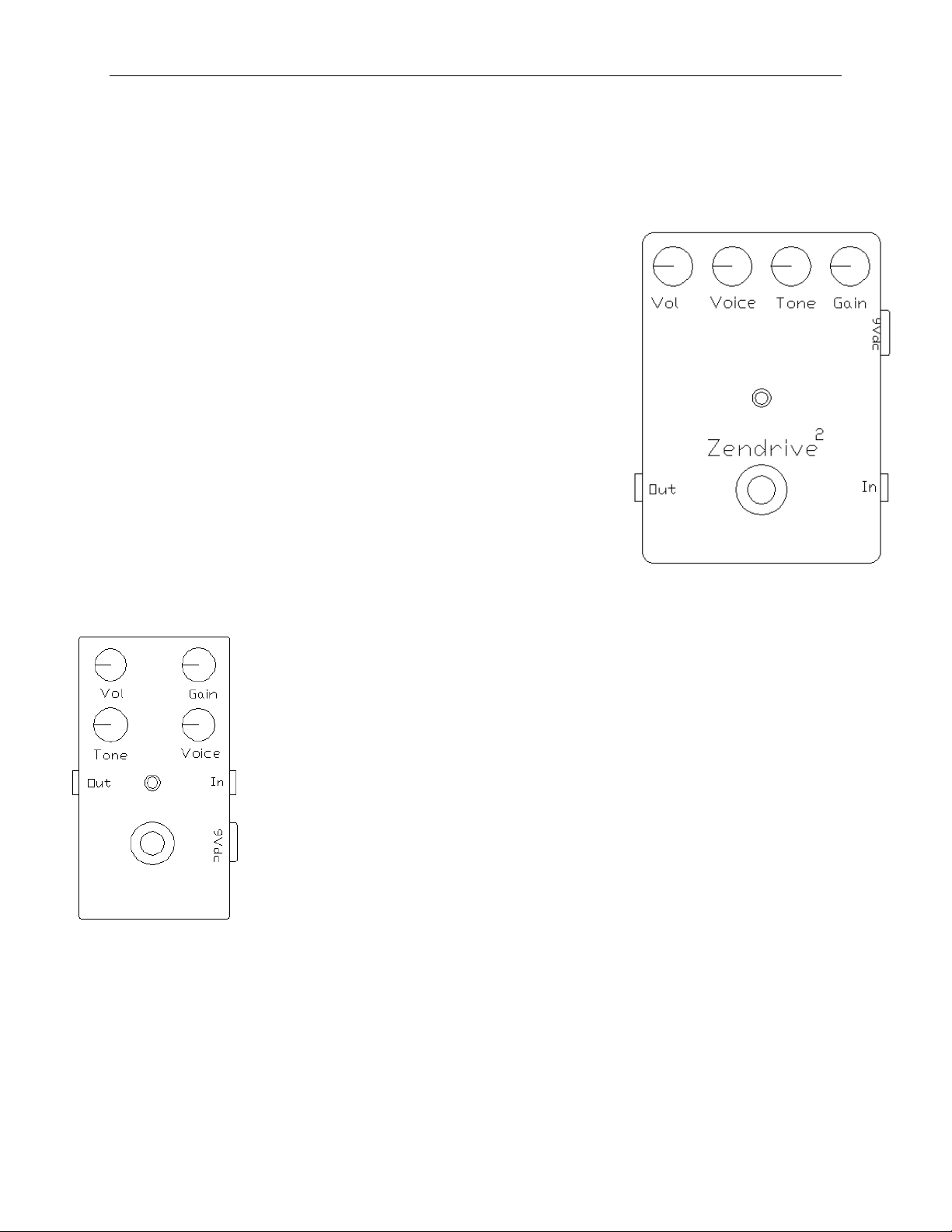
Zendrive, Zendrive 2, Mosferatu, Distortion and Nu-Valve Pedals
The above pedals have the following common configuration
(Diagram A):
•Vol ( ume), Gai n, Tone and Voi ce knobs
•In/ Out jacks
•9V DCadapter jack
•St at u s L ED
•Bypass foot swi tch (tr ue bypass)
•9V battery clip (inside the unit, except on Zendrive 2 and
Nu-Val ve
Pedal Quick-Start Guide
Diagram A
: Zendrive, Zendrive
2, Mosferatu, Distortion and
Nu-Valve Pedals

Hermida Audio Technology Pedal Quick-Start Guide
Page 2of 5
Knob Functionality
1. Vol(ume) - Adj ust s t he over al l vol ume of t he uni t . The full y count er cl ockw i se
position is zero.
2. Ga i n - Adjusts the amount of gain in the unit . For cleaner settings, r otate
count er clockw i se. The maxi mum gai n i n t he pedal i s al so l i mi t ed by t he Voi ce knob
set t i ngs. To set the maximum gain in the pedal, the Voice knob must be rotated fully
clockwi se.
3. Voice -“ Tunes” t he pedal t o t he ampl i fi er and gui t ar . The Voi ce knob per for ms t w o
functions:
a. Limits or increases the total amount of gain in the pedal. To limit the gain,
rotatecounterclockwise.To increasethegain,rotateclockwise.
b. Adjusts t he bot t om-end r esponse of t he pedal . To i ncr ease t he bot t om-end
response,rotatecounterclockwise.To reducethebottom-end, r ot at e t he
cl ockw i se. Remember t o adj ust t he Gai n knob t o compensat e for changes i n
theoverall gain of thepedal which occur duringtheVoiceknob adjustment
process.
4. Tone -Per for ms a basic “ high cut” funct ion. Wi th t he Tone knob set full y
count er clockw i se, hi gh fr equenci es ar e ful l y at t enuat ed.
5. In/ Out Jacks- Co n n ect a cab l e w i t h a ¼” p l u g b et w een t h e gu i t ar o r t h e o u t p u t o f
anot her pedal t o t he In jack. Connect anot her cabl e w i t h a ¼” pl ug bet w een t he Out
jack and another pedal,amplifier or recordingdevice.
6. 9V DCAdapter Jack -All pedal s ( except t he Zendr ive 2 and Nu-Val ve) can oper at e
with a9Vbattery or a9VDCadapter.Pleaseuse a9VDCadapter 200mA with a
cent er negat ive pl ug.
7. St a t us LED - The LED is On when the pedal is active. The LED is Off when it is being
bypassed.
8. Bypass Footswitch - Works in conjunction with the LED. Indicates when
el ect r oni cs ar e act i ve.
9. 9V Battery Clip -I n pedal s t hat oper at e w i t h a 9V bat t er y, r emove t he scr ew s on
back cover and the battery clip will be located close to footswitch. Ensure that the
cli p isconnected correctly beforeclosingtheback cover.
Hermida Audio Technology Pedal Quick-Start Guide
Page 3of 5
Pedals with Tubes: Zendrive 2 and Nu-Valve
Zendr i ve 2
The Zendrive 2 (Diagram B) i s a var i at i on of t he or i gi nal
Zendr i ve w i t h t he addi t i on of a dual t r i ode pr e-amp t ube. The
tubeisinstalled in asocket and can bereplaced with other pre-
amp t ubes. Di ffer ent t ubes can change t he voi ci ng and gai n of
thepedal.TheZendrive2 comeswith a 12AX7 tube, but can
al so use a 12AT7, 7025, 5751 or si mi l ar pr e-amp t ubes. Pl ease
cont act suppor t@her mi daaudio if you ar e unsur e of t he
compat i bi l it y of a t ube. The Zendr ive 2 incl udes a 9V DC
200mA adapter. It does not operate with a battery.
Nu-Valve
The Nu-Val ve (Diagram C) i ncl udes t w o small Nuvi st or t ubes. The pedal
operates with a 9V DC200mA adapter. The tubes are installed below the
footswitch in socketsand can be easily replaced without the need to
sol der . The t ubes suppl i ed w i t h t he Nu-Val ve ar e NOS ( New Ol d St ock )
6CW 4 Nu v i st o r t u b es. T h i s i s t h e o n l y t y p e t h at sh o u l d b e i n st al l ed i n t h e
pedal.
Diagr
am B
: Zendrive 2 pedal
Diagram
C
:
Nu
-
Val ve
pedal

Hermida Audio Technology Pedal Quick-Start Guide
Page 4of 5
Dual Boost Pedal
The Dual Boost pedal (Diagram D) offer s t w o dist i nct cl ean gai n
levelsselectableby afootswitch.
The Dual Boost has the following configuration:
1. Gai n A , Gai n B, T o n e an d Vo i ce k n o b s
2. In/ Out jacks
3. 9V DCadapter jack
4. St at u s On / Of f L ED an d Gai n A an d Gai n B L ED i n d i cat o r s
5. Bypass footswitch (true bypass) and A/ B togglefootswitch
6. 9V battery clip (located inside the unit)
Dual Boost Pedal Operation
1. Install abattery or DCadapter plug into theunit and connect theaudio signal from a
gui t ar or another pedal to t he In jack. Connect t he Out jack t o anot her pedal or
ampl i fi er .
2. The Status LED (lower middle) indicates if the unit is active (LED is On) or in bypass
mode (LED is Off).
3. The Gain A and Gain B LED indicators are located under the corresponding Gain
knob. One of the two LEDs should always be On when there’s power supplied to the
unit. The LEDs indicate which Gain channel will be active when the Status LED is On.
4. The Gain A and Gain B knobs are independent of each other and the A/ B footswitch
can only sel ect A or B.
5. To fully bypass the unit, press the On/ Off footswitch. The Status LED should turn
Of f .
Diagram D
: Dual Boost
pedal
Hermida Audio Technology Pedal Quick-Start Guide
Page 5of 5
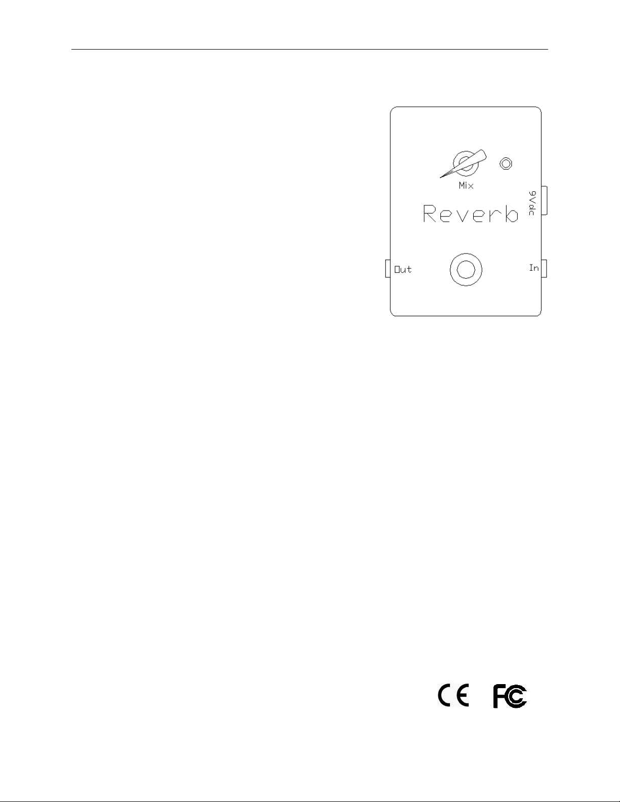
Reverb Pedal
The Reverb pedal (Diagram E) offer s a simpl e and
eff ect i ve w ay t o add r ever b t o your f avor i t e ampl i fi er .
The Reverb has both analog and digital signal paths in
order to maintain the warmth and r esponse of the
original signal. Bot h si gnal s ar e mi xed t oget her and sent
to theoutput of thepedal.
The Reverb has the following configuration:
1. Mix knob
2. In/ Out jacks
3. 9V DCadapter jack
4. St at u s L ED
5. Bypass foot swi tch (tr ue bypass)
6. 9V battery clip (located inside the unit)
Note: It is hi ghly r ecommended that the pedal be power ed
with a9VDCadapter (included) or thepower from your
pedal board. The pedal can operate with a battery but it will
consume t he bat t er y qui ckl y.
Rever b Pedal Oper ation
1. Install abattery or DCadapter plug into theunit and connect theaudio signal from
anot her pedal or gui t ar t o t he In jack. Connect t he cable fr om t he Out jack t o
anot her pedal or ampl i fi er .
2. Pr ess t he By p ass foot sw i t ch t o act i vat e t h e ped al . The St at us LED w i l l t ur n On.
3. While playing the guitar, adjust the Mix knob. The Mix knob bl ends t he wet r ever b
si gnal w i t h t he or i gi nal dr y si gnal fr om t he i nput .
4. So m e u ser s l i k e t o u se t h e am p l i f i er reverb in combination with theReverbpedal.
To do this, set your amplifier with the built-in reverb on and whileplayingthe
gui tar , acti vate the Rever b pedal. Adjust the Mix knob t o t ast e. Thi s set up w i l l all ow
you to have three different settings: one w i t h t he ampl i fi er r ever b onl y, one w i t h t he
Rever b pedal on l y an d one w i t h bot h t he am pl i fi er and t he pedal r ever bs on.
The Reverb pedal complies with thefollowingregulations/ testing:
Diagram
E: Reverb pedal
This manual suits for next models
6
Table of contents
Popular Music Pedal manuals by other brands


TC Electronic
TC Electronic DITTO+ quick start guide

TC-Helicon
TC-Helicon TALKBOX SYNTH quick start guide

GOD CITY INSTRUMENTS
GOD CITY INSTRUMENTS Socialist Jr. V1.1 Build guide

Wampler
Wampler ANDY WOOD GEARBOX quick start guide

Decibel Eleven
Decibel Eleven Switch Doctor Operation manuals

Zvex Effects
Zvex Effects Vexter SUPER RINGTONE quick start guide

DV Mark
DV Mark DVM Compressore owner's manual

Danelectro
Danelectro Cool Cat V2 Drive CO-2 instructions

aion
aion CRESCENT AMP DISTORTION manual

FuzzDog
FuzzDog Mutant Fuzz quick start guide

EarthQuaker Devices
EarthQuaker Devices Levitation Operation manual

Two notes Audio Engineering
Two notes Audio Engineering Torpedo C.A.B. user manual