HeroSpeed Dual Smart User manual

Dual Smart IP Camera
Quick Start Guide
Please read this manual carefully and keep it properly before using our
network camera products.
Related tools and documents of products, please download from
http://www.herospeed.net.

Statement
Thank you for using our products, please read this manual carefully
before trying.
This manual is applicable to network series products.
This manual may contain information that is technically inaccurate,
inconsistent in the product's function and operation, or in a typographical
error. Our company will update the context in the manual according to the
enhancement of product features. Updated content will be added in the
new version of this manual without further notice.
If there is manual description of the product does not match with the
physical, in order to prevail in kind.
Safety Precautions
Please avoid installing the product in a vibration or shock environment, and
keep the product away from electromagnetic interference (ignoring this
may damage the product).
In order to avoid heat accumulation, please keep good ventilation around
the device, and do not block the vent of the device.
Do not install indoor products in an environment that may be exposed to
water or other liquids.
Do not use the product in extremely hot, cold, dusty, or high humidity
environments.
This equipment must be stored in a dry and non-corrosive gas environ-
ment, and avoid direct sunlight.
Please avoid pointing the lens at strong light (such as lighting, sunlight or
laser beam, etc.), otherwise it will damage the sensor.
Power must be under safety certification, Its output voltage, current,
voltage polarity and operating temperature must comply with the power
requirements of this equipment.
When using this equipment in thunder and lightning conditions, please pay
attention to install lightning protection device or cut off the power.
In order to get high quality video and pictures, make sure your internet
connection is stable and smooth.

When the device is connected to the Internet, it may face network security
issues. Please strengthen the protection of personal information and data
security.
Please understand that you are responsible for properly configuring all
passwords and other related product security settings, and keeping your
user name and password properly.
The following exemptions or limitations of liability, please pay special
attention to:
Disclaimer
As a result of the following reasons, if the product interrupts or terminates
the service for any of the following reasons, the company shall not be
liable for personal injury or property damage to you or a third party.
Failure to install or use properly as required; for the sake of national or
public interest; force majeure; your own or third-party reasons (including
but not limited to the use of third-party products, software or
components, etc.
The company has not expressed or implied that this product is applicable
to special purpose.This product may not be used in medical / safety
equipment or other applications where there is a breakdown of the
product that could result in life-threatening or personal injury, as well as
hazardous or non-humanitarian hazards such as weapons of mass
destruction, biological and chemical weapons, nuclear explosions or any
unsafe use of nuclear energy use. Any loss or liability arising out of the
above use will be at your own risk.
This product, when properly installed and used, can detect unauthorized
intrusion during a particular delight but can not avoid accidents or
personal injury or property damage. In your daily life, you should be vigilant
and strengthen your safety awareness.
The Company is not responsible for any indirect, incidental, special
punitive damages, claims, loss of property or loss of any data or
documents. To the maximum extent permitted by law, the liability for
compensation of company is not exceed than the amount you paid for this
product.

1. Product Introduction
Dual Smart IP camera(Hereinafter referred to as IPC) is a new tempera-
ture measuring network camera integrating network remote monitoring
function, video server function and high-definition camera function.
The IPC has a built-in temperature measurement module, which has the
characteristics of high temperature measurement sensitivity, fast speed,
and safe use.
The IPC is suitable for installation on the security gate. When the target
passes through the security gate, the WEB interface will display the
human body heat map and test temperature. When the temperature of
the human body exceeds the set threshold temperature, the IPC will make
corresponding linkage alarms, such as flash alarm and sound alarm.
1.1. Product Description
1.2. Introduction Of Product Appearance
Housing
Mounting brackets
Lens
Flash lamp
Loudspeaker
Temperature
measurement module
MIC

1.3. Cable Description
①
Alarm interface: including alarm input and alarm output, a group of inputs,
a group of outputs and RS485 (used to connect external devices with
RS-485 interface).
②
Audio input interface: 1 channel audio input, used to connect audio pickup
to collect sound.
③
Audio output interface: 1 audio output, used to connect speakers and
other equipment to output audio.
④
Power interface: support DC12V, POE power supply. If it is DC12V, please
connect the positive and negative power supply correctly.
⑤
Network port interface: used to access Ethernet through RJ45 and power
the device through POE.
⑥
Reset interface: Long press the reset button for 10 seconds, the device
will be restored to the factory default parameters.
Alarm Input Alarm Output RS485
123456
+ - A B 485+ 485-
④
③
①
⑤
⑥
②
AUDIO IN
AUDIO IN
AUDIO OUTAUDIO OUT

2. Product Installation
2.1. Instructions Before Installation
2.2. TF Card Installation
If you need to use an TF card to store video, pictures and other data, please
install the TF card before installing the device. If you don't need to use TF
card to store data, please skip this chapter.
After installing the TF card in the IPC, you need to install it
according to the method before disassembly, otherwise it
will affect the airtightness of the camera and thus affect
the normal use of the device.
Warning
The wall to be installed should have a certain thickness and can
withstand at least 4 times the weight of the camera and mounting
accessories.
If the device is installed on a concrete wall or ceiling, you need to install
expansion screws before installing the bracket. (Please note that
the holes of the expansion screws must be consistent with the mounting
bracket)
If the device is installed on a wooden wall, the bracket can be directly
installed on the wall with self-tapping screws.
When you pick up the camera, do not directly pull the cable at the rear
of the camera. Otherwise, it may damage the waterproof performance
of the camera or cause circuit problems.
Before installation, please check whether the equipment in the packing box
is intact and all accessories are complete.

The camera supports wall mounting, ceiling mounting and tripod mounting,
and different installation methods can be selected according to different
installation environments.
2.3. Install the IPC
Step 1 There is a TF card slot on the back of the device, then use a phillips
screwdriver to unscrew the TF card slot cover.
Step 2: Insert the TF card into the card slot slowly, and when you hear a
"click" sound, the installation is successful.
Step 3 Close the TF card cover and tighten the screws.
①
②
③
2.3.1. Wall Mounting
Note: Wall mounting and ceiling mounting are the same. For ceiling mounting,
please refer to the wall mounting method.
Step 1 Choose a suitable installation wall, then paste the attached installation
sticker on the wall. Punch 4 φ6mm installation holes according to the label
on the sticker, then insert the expansion tube into the hole.

Step 3 Use a hexagon wrench to loosen the fixing screws, then adjust the
camera to a proper angle, and tighten the fixing screws to complete the
installation.
Step 2 Arrange and connect the power cables, network cables and other
cables of the device, and insulate the power cables. Clip the cable into the
cable outlet. Align the base hole with the sticker hole, and fix the device to
the wall with screws.
After the IPC is installed, you need to configure functions and set parame-
ters for it. You can configure related functions through the browser.
3. Instructions
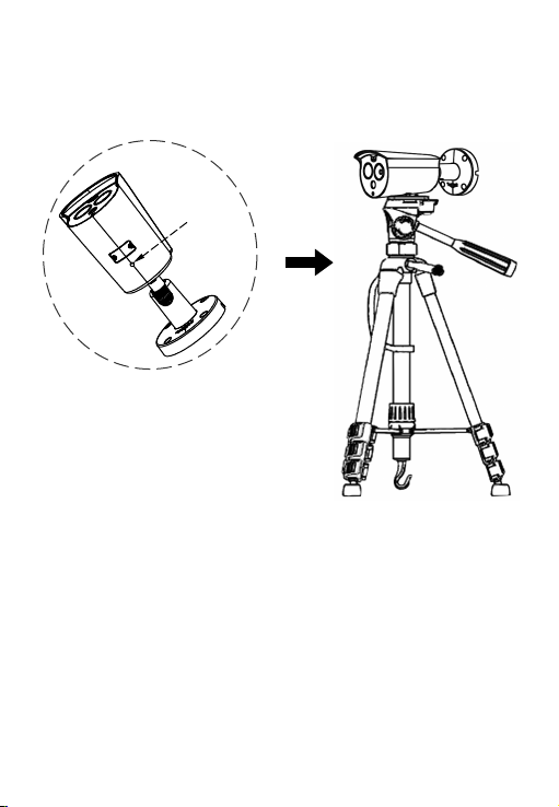
Align the screws on the top of the tripod with the mounting holes on the
bottom of the camera and lock the screws to fix.
2.3.2. Tripod Mounting
Tripod hole
3.1. Network Setting
The default IP of all cameras is 192.168.1.168. The IPv4 address of the
computer must be in the same network segment as the IP address of the

(1) Add the same network segment IP as 192.168.1.168 (camera factory
default IP) in the computer, such as 192.168.1.165.
Prepare the network configuration:
Steps to add an IP address to the Windows system:
Step 1: Click [ ] Start → [Control Panel] → [Network and Sharing
Center] → [Local Network] → [Properties] → [Internet Protocol Version 4
(TCP/IPv4)] → [Advanced] to enter the advanced TCP/IP setting interface.
Steps 2: Click [Add] in the IP address (R) position, enter the IP address as
192.168.1.165 and the subnet mask 255.255.255.0, and click [Add] →[OK]
→ [OK] → [OK].
(2) Connect camera and PC by network cable in the same LAN, power on.
Connecting as following (PoE switch, camera, PC connection photo).
IP camera. To enable the camera to access the network smoothly, plan the
available IP network segments based on the actual network environment.
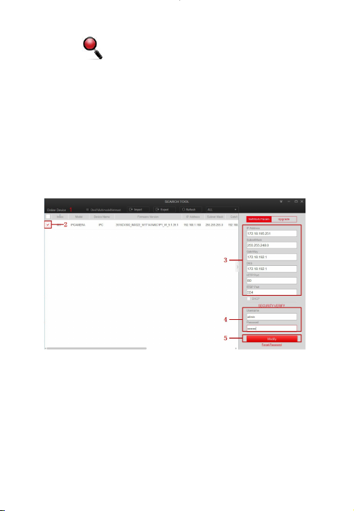
The network configuration steps are as follows:
Step 1:Open [ Search Tool] (Version 7.2.45.6 and above, please install
Search Tool from http://www.herospeed.net).
Step 2: Check 192.168.1.168.
Step 3: Modify the relevant network parameters such as IP on the right side of
the interface
Step 4: Enter the user name (default is admin) and password (default is admin)
of the device.
Step 5: Click [Modify] → [Confirm].
Step 6: Click [Refresh] to find the IP address that has been modified, which
means that the network configuration is successful.
NOTE: When configuring network parameters, ensure that the IPC address and
the computer's IPv4 address are on the same network segment.

Step 1: Open the IE browser, enter the IP address of IP Camera (if the IP has
not been modified, please enter the default address http://192.168.1.168),
and press [Enter].
Step 2: Click [Download], download the plug-in, close the browser, and follow
the prompts to install the plug-in.
3.2. Modify Password
Step 3: Enter the user name (admin) and password (admin) of the device,
and click [Login].

Step 4: Click [Modify], enter the password, confirm the password, and set
the security question, click [Key Export] → [Save].

3.4. Parameter Configuration
Enter real-time preview interface after login.
3.3. Real-time Preview
Click [Configuration] to enter the parameter configuration interface of the
device, which includes local configuration, system, local network, video,
image, event, body temperature measure and other functional configura-
tions. Users can selectively set these functions according to actual applica-
tion scenarios to achieve the best monitoring effect.

Step 1: On the main interface, click [Configuration] → [Temperature
Measure] → [Temperature Measure] to enter the body temperature
measurement interface.
Before adding devices, please make sure that the IP addresses of NVR and
IPC are on the same network segment and do not conflict. Click [Channel]
→ [Camera] → [Search] under the NVR main menu, check the devices to be
added, and click [Add].
NOTE: In the main menu of NVR, you can also perform operations such as
video settings, video playback, motion detection, and encoding parameter
settings.
3.6. NVR adds IPC
3.5. Body Temperature Measure Configuration
Step 2: Configure related temperature measurement parameters and click
[Save].
Step 3: Click [Linkage Method] → [Arming Schedule] to set the arming time.
Step 4: Click [Linkage Method] and set the linkage method.
Step 5: Click [Save].

3.8. Mobile App Access
Scan the QR code below to download and install the BitVision App.
Step 1: Open your browser and visit http://www.herospeed.net/.
Step 2: Click [PC Client] → [iVMS320 (Windows)] or [iVMS320 (Mac)] to
download the latest version of the video management system [iVMS320].
Step 3: Follow the prompts to install and add devices to view and manage
the devices.
3.7. iVMS320 Client Access
After registering and logging in, you can add the device, and remotely view
and manage the device on the mobile phone.
Table of contents
Other HeroSpeed Security Camera manuals


