Herron Audio VTSP-1A/166 User manual

VTSP-1A/166
VTSP-1A/166
Owner’s Manual
Vacuum Tube
Stereo Preamplifier
Vacuum Tube
Stereo Preamplifier

Herron Audio Vacuum Tube Stereo Preamplifier
Herron Audio Vacuum Tube Stereo Preamplifier
©2003 Herron Audio
Division of Herron Engineering, Inc.
12685 Dorsett Road
# 138
St. Louis, MO 63043
314.434.5416
314.434.6629 fax
Table of Contents
3 Introduction
4 Features
6 Design Considerations
7 Front Panel Features
10 Rear Panel Features
12 Installation and Operation
13 Other Considerations
14 Changing Tubes
15 Technical Specifications
Owner’s Manual
Please read the Owner’s Manual completely BEFORE operating the unit.
Welcome!
Welcome!
Thank you for your investment in
the Herron Audio Vacuum Tube
Stereo Preamplifier, a masterpiece
of high-precision audio playback
equipment. It is designed to be the
finest product of its type available.
The care in engineering and
manufacturing of this product
anticipates a lifetime of musical
enjoyment.
The original Herron VTSP was
created to provide a research plat-
form for the development of other
Herron Audio components. We
recognized the need for a trans-
parent line stage preamplifier that
provided control of the signal
source, level, and channel bal-
ance. Existing available
equipment, regardless of price,
failed to meet these needs due to
distortion and coloration intro-
duced into the signal and
exhibited wide variations in unit-
to-unit quality.
The VTSP-1A/166 employs a
basic gain stage architecture simi-
lar to the highly praised VTPH-1
phono preamplifier. Years of
research into circuit design and
component performance were
applied to the development of the
VTSP-1A/166, and new implemen-
tations of components led to a
breakthrough in performance
while maintaining conservative
operation. The unconventional
design of the VTSP-1A/166 has
resulted in a level of performance
unequaled in the audio industry.
Not only did this preamplifier
meet our design objectives for a
research platform, it also provides
the most musical and non-intru-
sive control of any unit of its type.
As with all Herron Audio prod-
ucts, the VTSP-1A/166 is
engineered to be reliable and user
friendly to overcome the fears
many have expressed concerning
vacuum tube components.
Manufacturing of the unit is
performed under the tightest of
quality controls.
Its limited production permits
hand matching of components to
the most exacting standards in the
industry. Tubes are burned in,
bench tested, and matched to
extremely tight tolerances both as
sets within a given unit and to the
original design to ensure unprece-
dented performance and lack of
unit-to-unit variation.
Owner’s Manual
one
Owner’s Manual
Please read the Owner’s Manual completely BEFORE operating the unit.
The power supplies of all Herron
Audio products reflect the engineer-
ing innovation that allows the
Herron VTSP-1A/166 Preamplifier to
provide the highest musical satisfac-
tion without the artifacts produced
by most other tube-based compo-
nents. This power supply provides a
rigid and unwavering voltage source
to the tubes, producing remarkable
resolution of musical events in time
and sound stage.
The circuit board layout reflects
consideration of all of its electrical
properties in order to achieve out-
standing audio performance with
greater consistency than hand
wiring. Compromise was not an
option. The best possible perfor-
mance was the only consideration.
The unique design of the Herron
VTSP-1A/166 Preamplifier, along
with its conservative operating para-
meters, means that owners can
expect the industry’s highest level of
performance to be maintained over
the extended life of the unit.
All members of Herron Audio
staff are audiophiles who regard the
accurate reproduction of music as
one of the highest applications of
the engineering arts. We at Herron
Audio believe in the pursuit of audio
perfection. We hope you enjoy the
fruits of our efforts. If you have any
comments, suggestions, or ques-
tions, please contact us at
314-434-5416.
three
Herron Audio Vacuum Tube Stereo Preamplifier
Features
Features
Operating the Herron VTSP-1A/166
Preamplifier is easy and straightfor-
ward. The unit has been designed to
be exquisitely simple and user
friendly, with its operational readi-
ness easily monitored.
A new and special feature of the
VTSP-1A/166 is the perfect tracking
volume control. This innovative
use of servo control provides
extremely accurate tracking
between separate electronic
stepped attenuators for each chan-
nel. This technology provides
precise channel-to-channel balance
across the full volume range while
retaining the convenience of a con-
ventional volume knob. This
approach does not use a conven-
tional potentiometer as a volume
control thus eliminating a major
source of signal distortion in many
of the competing units. Our servo
implementation also has the ability
to handle a much higher signal
level than many competing
designs. Where some other units
tend to limit the signal during
dynamic peaks at the input, the
VTSP-1A/166’s perfect tracking sys-
tem, with its substantial headroom,
can easily handle large voltage
swings from even the most
advanced phono reproduction
equipment, high quality digital
sources, and advanced signal
processors in home theater
systems.
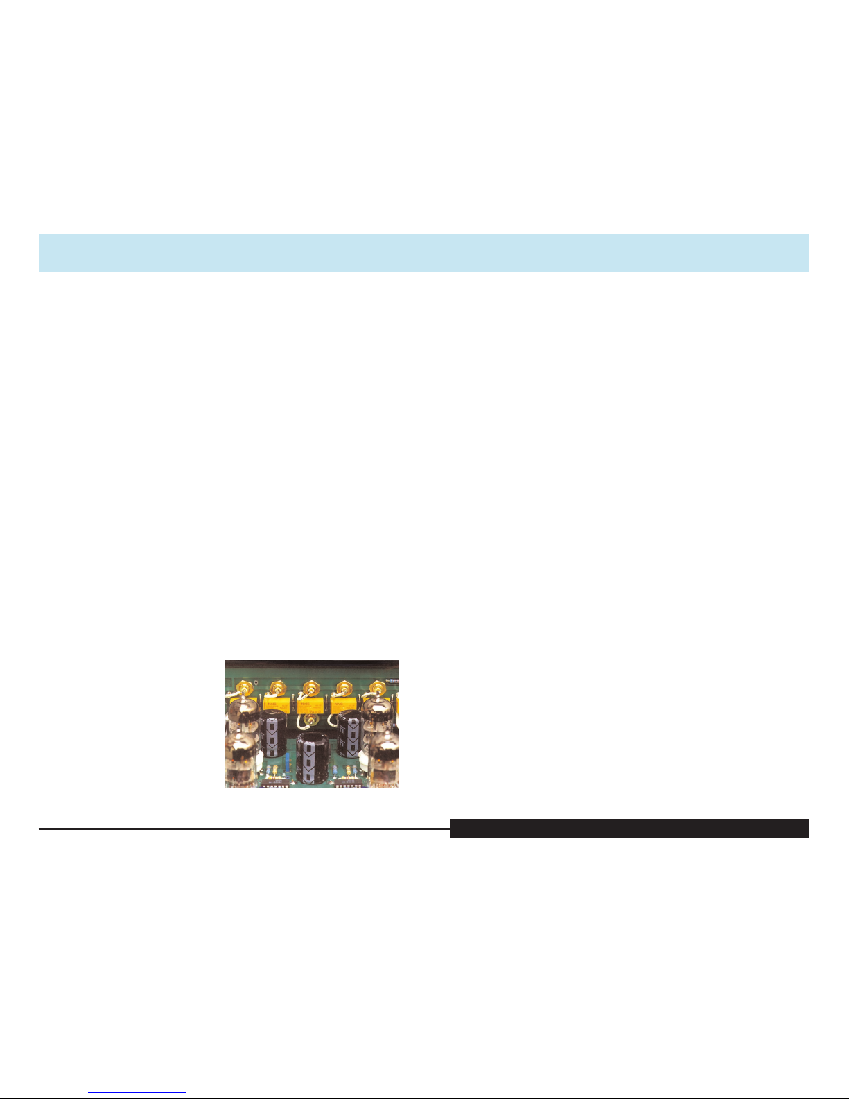
Source input selection in the
VTSP-1A/166 incorporates gold con-
tact sealed relays located at the input
connectors keeping the signal path
length to an absolute minimum.
This innovative configuration elimi-
nates the distortion-generating
wipers of conventional selectors and
long runs of wire from the rear panel
to the switch. An additional benefit
is that in using sealed units, the con-
tacts are not prone to corrosion, dirt,
or the same kind of wear as conven-
tional selector switches.
Herron Audio Vacuum Tube Stereo Preamplifier
two
Relays located at inputs

Owner’s Manual
Please read the Owner’s Manual completely BEFORE operating the unit.
Front Panel Features
Front Panel Features
Automatic Mute and LED
Indicators
The VTSP-1A/166 features a fully
functional front panel capable of a
wide range of signal control and
easily-monitored operational readi-
ness of the unit. When the
VTSP-1A/166 is powered up, the
automute feature is engaged until
the unit is ready for operation. The
first indicator on the panel is the
POWER LED, which indicates the
unit has been turned on. After a few
moments, the FILAMENTS LED
gradually brightens, as the voltage to
the filaments slowly increases. When
the unit is ready to operate, the
OUTPUTS LED comes on and the
automute is disengaged allowing sig-
nal to be passed to the main outputs.
This process generally takes about a
minute, but can take a little longer if
the unit has not been operated for
an extended period of time. This
controlled start-up process helps
maintain the high level of perfor-
mance of the VTSP-1/166 and
greatly prolongs tube life while
protecting sensitive connected
components.
Selector Switch
The five-position Selector switch is
used to choose the input signal, and
remotely activates special sealed
relays used to connect the input sig-
nal to the preamplifier’s circuitry.
The five positions in the Selector
switch are:
• AUX 1
• AUX 2
•CD
• TUNER
• VIDEO
The selector switch positions cor-
respond with the identically named
inputs on the back panel.
If you have a phono preamplifier,
such as the Herron Audio VTPH-1,
we recommend that you connect it
to the AUX 1 input, which is conve-
niently located next to the
five
Herron Audio Vacuum Tube Stereo Preamplifier
four
Design Considerations
Design Considerations
•Perfect tracking volume 166 step control system with unprecedented
precision and dynamic range
• Infinite resolution indirect signal path balance control
• All-tube design operated conservatively for long life
• Relay input switching eliminates switching distortion
• Star grounding for low interference susceptibility and clean signal path
• Zero feedback—no feedback loops in the audio circuitry
• Super-low noise
• High input signal capacity without overload; see technical specifications
• Gold plated TIFF RCA and ground connectors
• Hand-picked components for accurate response and consistent unit-to-unit
quality
• Automatic muting at startup and shutdown
• 72,000 µF of power supply energy storage capacitance
• 4 levels of high voltage regulation
• Regulated soft-start DC filament supply
• Regulated tube bias supply
• Toroidal power transformer
• Rugged 0.10” thick aluminum chassis with 0.25” thick heavily anodized
faceplate
• Reversing power line (AC) polarity switch for minimizing line-to-chassis
reactive currents and noise pickup
• Controlled warm-up of tube filaments and high voltage for extended tube life
• Low plate operating currents for extended tube life and cool operation
• Front panel indicators for power, filament voltage, and output/mute/
monaural
• Each unit is given an extensive burn-in, including rigorous bench and
listening tests

Owner’s Manual
Please read the Owner’s Manual completely BEFORE operating the unit.
the balance control is in the cen-
tered position.
Volume Control
The volume control knob of the
VTSP-1A/166 operates a servo that
controls the positions of two (left
and right) electronic stepped
attenuators. This unique design
provides the feel of a conventional
volume control and the benefits of
much lower distortion and better
tracking from a unique state of the
art electronic 166 step volume
attenuator. Rotating the control
clockwise increases the volume;
rotating the control counter-clock-
wise decreases the volume. Its
unique operation and integration
into the VTSP-1A/166 contributes
to this preamplifier’s outstanding
performance.
Occasionally, due to static dis-
charge, the channel-to-channel
tracking may require adjustment.
An automatic servo reset is easily
initiated by placing the Mute/Listen
switch in the MUTE position, then
returning it to the LISTEN position
or by turning the volume control
fully counter-clockwise (against
the stop) and returning it to the
desired level.
Step changes during adjustment
of the volume control will be most
audible for a short period of time
just after the line stage or selected
input equipment is powered on.
Normally these step changes may be
heard at roughly the 8:30 o’clock
position and at high volume set-
tings. Though not necessary, it is
good operating practice to adjust the
volume control to its lowest setting
when switching inputs or when
powering up or powering down
the preamplifier.
MUTE / LISTEN Switch
The Mute/Listen switch is located
below and to the left of the LEDs.
This switch controls the muting of
the main outputs (but does not mute
the tape outputs). When in the
LISTEN position, the signal is passed
to the main outputs directly. When
in the MUTE position, the signal
is disconnected from the main
outputs, and the volume is
automatically turned down.
The OUTPUTS LED glows red
when the switch is in the MUTE
position.
In normal operation, the
MUTE / LISTEN switch is placed
in the LISTEN position.
seven
Herron Audio Vacuum Tube Stereo Preamplifier
GROUND terminal on the back
panel. The selector switch indicates
the signal source that is used for the
TAPE OUT on the back panel and
also the MAIN 1 and MAIN 2 out-
puts (when the TAPE / SOURCE
switch is in the source position).
TAPE / SOURCE Switch
The TAPE / SOURCE switch is
located below and to the right of
the selector switch. This switch con-
trols the preamplifier main output
source. When the switch is in the
SOURCE position, the selector
switch determines the signal used
for both tape and main outputs.
When the switch is in the TAPE
position, the signal entering the
inputs labeled TAPE on the back
panel is used as a source for the
Main Outputs.
The TAPE / SOURCE switch can
also be used to support an external
signal processor.
In normal operation, the TAPE /
SOURCE switch is placed in the
SOURCE position.
MONO / STEREO Switch
The MONO / STEREO switch is
located in the middle of the front
panel. When the switch is placed
in the STEREO position, the left and
right channel signals remain sepa-
rated. When the switch is placed in
the MONO position, the left and
right channels are combined into
a single “summed” signal.
The OUTPUTS LED lights up in a
combination of red and green with
the MONO / STEREO switch in the
MONO position.
In normal operation, the MONO /
STEREO switch is placed in the
STEREO position.
Balance Control
The VTSP-1A balance control pro-
vides a full range of adjustment for
relative balance between the right
and left channels. In the centered
position, each channel is equal in
signal sensitivity. Rotating the bal-
ance control in the clockwise
direction (to the right) decreases the
volume in the left channel
(relative to the right channel).
Rotating the balance control in a
counter-clockwise direction (to the
left) decreases the volume in the
right channel (relative to the left).
In the fully clockwise or counter-
clockwise position, the left or right
channel respectively will be muted.
Normal operation is provided when
six
Owner’s Manual
Please read the Owner’s Manual completely BEFORE operating the unit.
nine
“B” position. Repeat the process,
listening to the same source. Place
the AC polarity switch in the posi-
tion that sounds best.
Once set, it is not necessary to
change the AC polarity unless your
electrical service changes, or the unit
is connected to a different electrical
outlet. If the unit is used with the
Herron Audio VTPH-1 phono pream-
plifier, we suggest that both the
VTPH-1 and VTSP-1A/166 use the
same AC polarity switch setting.
Inputs
The inputs are segregated by channel:
the upper bank contains the left
channel inputs, the lower contains
the right channel inputs. Selector
input pairs are arranged vertically.
The labeled input pairs, except for
the pair labeled TAPE correspond to
those available on the selector switch
on the front panel. The input is selec-
table using the TAPE / SOURCE
switch.
RCA input plugs should be
inserted firmly into the input jacks
while the unit is powered down. Any
individual ground bleed connections
should be connected to the gold
ground lug located near the end of
the banks of input jacks.
It may be desirable to connect a
source’s right channel first, followed
by the left.
Outputs
There are two types of outputs in the
VTSP-1A/166. The main outputs are
intended for connection to high
quality power amplifiers or a multi-
channel electronic crossover. Two
pairs of main outputs are provided
so that users may distribute the
audio signal to multiple systems, or
to simplify using multiple amplifiers
in a complex or multi-way speaker
system.
The tape outputs are provided to
allow monitoring of the audio signal
after the selector switch relays. The
signal from the tape output corre-
sponds to the input chosen by the
selector switch.
The operation of the Herron
VTSP-1A/166 Preamplifier is straight-
Herron Audio Vacuum Tube Stereo Preamplifier
Rear Panel Features
Power Connection
An IEC power cord connector is pro-
vided for attaching the Herron
Audio-provided power cord or
another chosen by the user.
POWER Switch
This is the unit’s POWER switch.
When placed in the on position, the
unit is powered up. At power up, the
unit is automatically muted until
full operational capabilities are
reached and the voltages are stable
at the tubes.
When switch is moved to the off
position, the unit is automatically
muted and powered down.
POWER LINE POLARITY Switch
This switch selects the power line
polarity.
AC line polarity may affect perfor-
mance. The following is the
recommended procedure for deter-
mining the best operation:
• Set the power line polarity switch
to the “A” position.
• Set the volume control to the
desired level and listen closely to
the quality of the reproduction.
This will be used as a baseline for
determining AC polarity.
• Change the AC polarity of the
preamplifier by switching the
power line polarity switch to the
eight
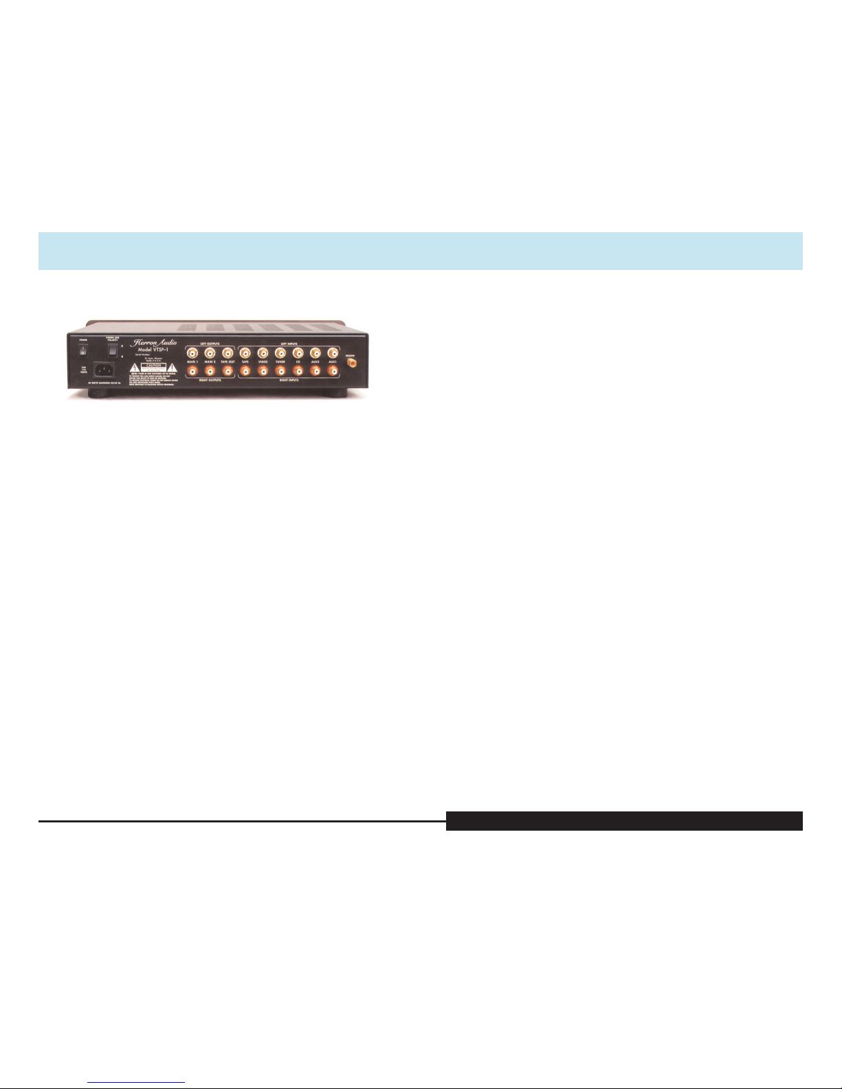
Rear Panel Features
The rear panel was designed for flexibility and ease of access to less-fre-
quently used functions. The high precision RCA input jacks are heavily
gold-plated to minimize signal-degrading corrosion. The special insulation
material in the RCA connectors maintains purity of the signal from the input
cable into the unit.

Owner’s Manual
Please read the Owner’s Manual completely BEFORE operating the unit.
Other Considerations
Other Considerations
eleven
With the higher definition and detail available through
the VTSP-1A/166, careful attention to the set-up of other
components will yield greater benefits. There may also
be considerable gains from the upgrade of existing
electronics.
Turntable mounting can improve performance by
providing a more stable operating platform for the arm
and platter. We have found that attention to turntable
and platter leveling, fine balance of springs, dampening
of vibrations, etc., can improve performance in many
systems.
Tonearm balance, minor changes in antiskate, proper
arm alignment, etc., all contribute to gaining the best per-
formance. For certain arms, the use of a dampening wrap
can improve performance dramatically.
We recommend the use of high-quality interconnecting
cables between the source components and the VTSP-1A/166,
and between the VTSP-1A/166 and components down-
stream of it (the power amplifiers and speakers).
Due to the increased definition of detail, it may be nec-
essary to make minor adjustments in speaker position or
active crossover settings to optimize their performance.
We have determined that minor time alignment changes
in a setup can produce major advances in the overall qual-
ity of the reproduced signal bringing the listener closer to
the original performance.
Herron Audio Vacuum Tube Stereo Preamplifier
Installation and Operation
Installation and Operation
Procedure
1. Position the unit in a well-ven-
tilated area on a firm, stable
surface, away from equipment
that generates alternating mag-
netic fields such as motors,
transformers, etc. Magnetic
fields of this type can introduce
hum into the signal path.
2. Connect the signal cables from
the source components (CD,
phono preamplifier, VCR,
tuner, etc.) to the VTSP-1’s rear
panel jacks, left-to-left and
right-to-right. Connect the
ground bleed wires to the
ground connector of the phono
preamplifier.
3. Plug the amplifier and tape
recorder input cables into the
corresponding outputs, left-to-
left and right-to-right.
4. Plug the power cord into the
VTSP-1A preamplifier. Make
sure it is firmly seated into the
IEC socket prior to inserting the
plug into an AC outlet.
5. Plug the power cord into a 115
volt (U.S. spec units) AC outlet.
6. Power up the unit by switching
on the power switch.
7. Observe the LEDs for appropri-
ate operation (see the Front
Panel Features section). Listen
carefully for the click of the
automute engaging the outputs.
8. Power up the source compo-
nent to be used and position
the selector switch to choose
that component.
9. Once the unit is powered up
and operating, power up the
down-stream amplifier(s) and
crossover, if any, as recom-
mended by their
manufacturers.
10. With the Volume control in the
lowest position, gradually
increase the gain until the
desired level is reached.
11. When the entertainment ses-
sion is complete, it is suggested,
but not required, that the VTSP-
1 be powered down after the
crossover, amplifiers, and tape
recorder, and before the source
components.
ten
forward. As with any fine audio component, careful set-up and integration into
one’s system is important for optimum performance, safety, and reliability.
Please read through the following set-up instructions completely prior to oper-
ating the unit.
Owner’s Manual
Please read the Owner’s Manual completely BEFORE operating the unit.
VTSP-1A/166 Technical Specifications
Tube complement: 4 x 6922
Frequency Response: 1 Hz to beyond 100 kHz, 20 Hz to 20 kHz ±0.1 dB
(volume control at 8 o’clock)
Volume Control: 166 position electronic stepped attenuator
Volume Tracking: Maximum differential: +/- 0.1 dB channel to
channel
Gain: 14 dB
Input Impedance: 100,000 Ohms
Output Impedance: 100 Ohms nominal at 1 kHz
Absolute Polarity: Inverting
Power Supply: 72,000 µF of energy storage
4 levels of high voltage regulation
Regulated soft start DC filament supply
Regulated tube bias supply
Toroidal power transformer
Power requirements: U.S.: 120 VAC 60 Hz, 30 VA, Fuse 1/2 amp
250 volt slow blow
Export: 230 VAC 50/60 Hz, 30 VA, Fuse 1/4 amp
250 volt slow blow
Input capacity: 18 Volts RMS
Dimensions: 19” wide x 3.5” high x 10” deep
Warranty: 5 years, parts and labor; 90 days on tubes
Manufactured by Herron Audio Division of Herron Engineering, Inc.
St. Louis, Missouri
thirteen
VTSP-1A/166 Technical Specifications
Herron Audio Vacuum Tube Stereo Preamplifier
We do not recommend changing
tubes for the purposes of “improving
sonic performance.” Tubes of even
the same part number (6922 in the
case of the VTSP-1A/166) from differ-
ent manufacturers and different
production lots generally vary consid-
erably in many operating parameters.
The Herron VTSP-1A/166 Preamplifier
has been optimized for the tubes that
were supplied by the factory. The orig-
inal tubes should provide many years
of good performance due to the con-
servative plate voltage and current
operating requirements of the Herron
Audio VTSP-1A/166 preamplifier.
If replacement tubes are required,
Herron Audio recommends the use
of our factory matched sets of tubes.
These tubes have been selected for
their superior performance and
have been matched much more
closely than tubes—even from the
same manufacturer—from other
suppliers.
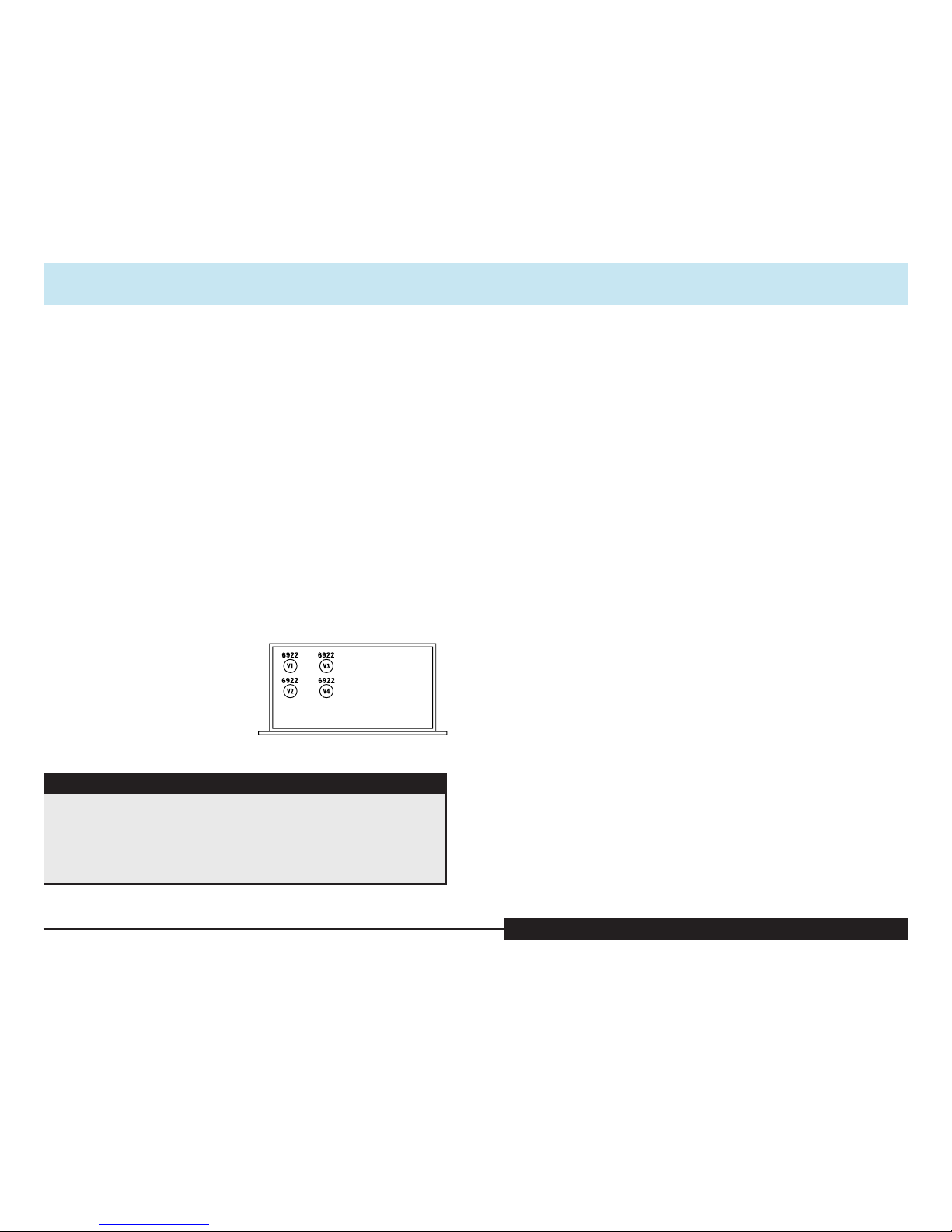
All tubes in the Herron
VTSP-1A/166 are of the type 6922.
If access to the interior of the
preamplifier is necessary, be sure to
install the grounding lug under the
top screw at the rear of the chassis
when reinstalling the cover.
When changing tubes, the
VTSP-1A/166 should be unplugged
and left off for a minimum of 30
minutes prior to opening the unit, to
insure that hazardous voltages in the
power supply have time to discharge
before entering the unit.
twelve
Changing Tubes
Changing Tubes
!!!!!
When changing tubes, the VTSP-1A/166 should be unplugged and left
off for a minimum of 30 minutes prior to opening the unit to insure that
hazardous voltages in the power supply have time to discharge before
entering the unit.
CAUTION CAUTION CAUTION CAUTION CAUTION CAUTION
Table of contents
Other Herron Audio Amplifier manuals

Herron Audio
Herron Audio VTSP-3A User manual

Herron Audio
Herron Audio M1 User manual

Herron Audio
Herron Audio VTSP-2 User manual

Herron Audio
Herron Audio VTSP-3A User manual

Herron Audio
Herron Audio VTSP-3 User manual

Herron Audio
Herron Audio VTPH-1 User manual

Herron Audio
Herron Audio HL-1 User manual

Herron Audio
Herron Audio M150 User manual

Herron Audio
Herron Audio VTPH-2 User manual

Herron Audio
Herron Audio M1A User manual


