Herron Audio VTSP-3 User manual
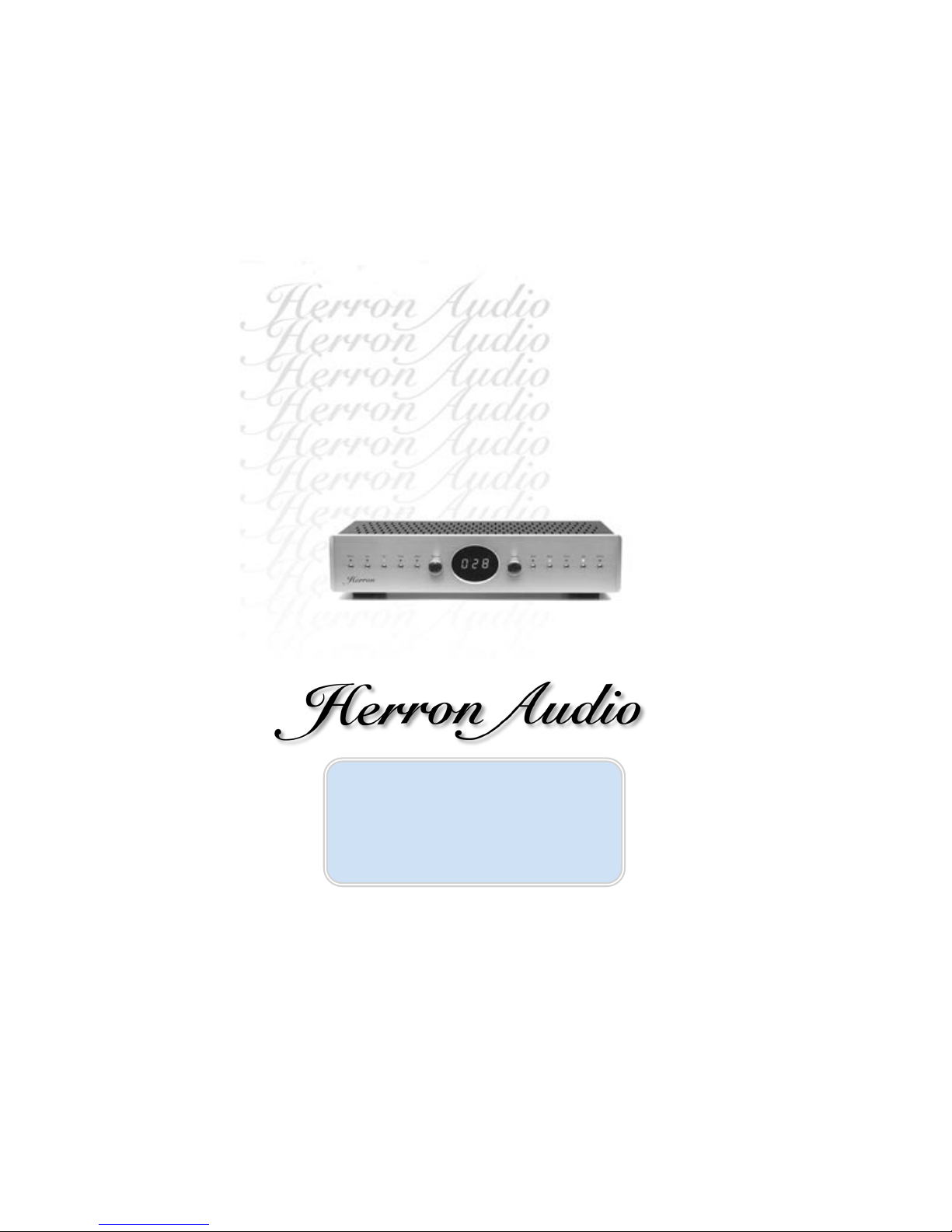
Vacuum Tube
Stereo Preamplifier
VTSP-3
VTSP-3
Owner’s Manual
Vacuum Tube
Stereo Preamplifier

VTSP-3 Vacuum Tube Stereo Preamplifier Owner’s Manual
Please read the Owner’s Manual completely BEFORE operating the unit.
one
Welcome!
Welcome!
Thank you for your investment in the Herron Audio VTSP-3 Vacuum Tube
Stereo Preamplifier, a milestone in high-precision audio playback equipment.
The VTSP-3 is a new design, benefiting from insights gained during continu-
ous refinement of the highly-praised and award-winning VTSP-2. The care in
engineering and manufacturing of this product anticipates a lifetime of
musical enjoyment. Years of research into circuit design and component
performance were applied to the development of the VTSP-3 and new imple-
mentations of components have led to a breakthrough in performance while
maintaining conservative operation for extended tube life. As with all Herron
Audio products, the VTSP-3 is engineered to be reliable and user friendly.
Manufacturing of the VTSP-3 is performed under the tightest of quality
controls. Its limited production permits hand matching of components to
the most exacting standards in the industry. Tubes are burned in, bench
tested, and matched to extremely tight tolerances, both as sets within a given
unit and to the original design to ensure unprecedented performance and lack
of unit-to-unit variation.
Owner’s ManualVTSP-3 Vacuum Tube Stereo Preamplifier
©2007 Herron Audio
Division of Herron Engineering, Inc.
12685 Dorsett Road
# 138
Maryland Heights, MO 63043 (St. Louis area)
314.434.5416
314.434.6629 fax
www.herronaudio.com
Table of Contents
Introduction 1
Features 2
Design Considerations 5
Front Panel Features 6
Rear Panel Features 8
Remote Control 10
Installation and Operation 11
Changing Tubes 13
Technical Specifications 14

The VTSP-3 incorporates an
infrared remote control for conve-
nient operation of many of the
preamplifier’s front-panel functions.
This remote uses 38kHz modulation
and detection of this signal initiates
the VTSP-3’s decoder circuitry, which
is otherwise dormant in order to pre-
vent the unwanted noise usually
associated with remote control cir-
cuitry. A flashing red light in the
display window indicates the initia-
tion of the remote control decoding
process in the VTSP-3. When the red
light is off, this circuitry goes to
“sleep” mode.
The VTSP-3 utilizes two extremely
low distortion precision electronic
stepped attenuators (one for each
channel) in a fashion similar to the
VTSP-1A/166, and VTSP-2. The VTSP-3
has a total of 100 volume steps, and
the precise volume level is shown as
three digits in the front-panel display
window. The use of electronic stepped
attenuators ensures continued high-
quality performance without any of
the oxidation and corrosion that
degrades conventional mechanical
VTSP-3 Vacuum Tube Stereo Preamplifier Owner’s Manual
Please read the Owner’s Manual completely BEFORE operating the unit.
stepped attenuators and volume con-
trol potentiometer wiper contacts.
At startup the display on the VTSP-3
goes through a lamp test, and then suc-
cessively displays the model of the unit
“SP3” and the time in seconds from 60
(while the filaments and high voltage
are slowly brought on) until the unit
automatically un-mutes. The input dis-
play will show the last input in use
from the last time the unit was on.
When the countdown is complete the
mute will be disengaged (if it was not
on the last time the unit was shut
down), the function displays will indi-
cate the last state of use, and the
volume will be ramped up to a rela-
tively low level of 10. At this point the
user will be able to change the settings.
The VTSP-3 incorporates circuitry
to switch the phase of the audio sig-
nal by 180 degrees for absolute
polarity control. The amber “Invert”
light on the front panel will indicate
if the phase is being inverted. The
phase switching circuitry of the VTSP-3
is designed so that no coloration is
added in either mode and the true
effects of recorded phase polarity are
audible in either mode. The invert
mode can be controlled from both the
front panel and the remote control.
Note: When the invert mode of the
VTSP-3 is switched, the unit automati-
cally mutes before changing modes in
order to prevent any unwanted
“pops” during switching. The unit
unmutes after the invert mode is
changed. The process takes less than
a second.
The display brightness of the
VTSP-3 can be dimmed from both the
remote and the front panel by push-
ing the “Display” button. Operating
the “Display” button again will return
the brightness to its previous setting.
The blue “Display” indicator on the
front panel indicates dim-display
mode.
Source input selection in the VTSP-3
incorporates gold-contact sealed relays
located at the input connectors, keep-
ing the signal path length to an
absolute minimum. This innovative
configuration eliminates the
distortion-generating wipers of con-
ventional selectors and long runs of
wire from the rear panel to the switch.
An additional benefit of using sealed
relays, the contacts are not prone to
corrosion, dirt, or the same kind of
wear as conventional selector
switches.
The VTSP-3 has a power-polarity
switch on the back panel for revers-
ing the power line polarity
connection to the primary of the
power transformer. This can be used
to minimize the capacitive reactance
effects from the power line on the
audio quality of the unit. This switch
can be operated while listening in
order to determine the best-sounding
power polarity setting.
The “Video” input of the VTSP-3
can be placed in unity-gain mode by
pressing and holding the “Video”
button on the front panel for a few
seconds. The volume display will indi-
cate “PAS” on the display when the
pass-through mode is initiated; only
the video input will be at unity gain.
Selecting any other input will shut off
the pass-through mode, and the vol-
ume will return to 10.
Note: The pass-through mode
cannot be selected from the remote
control.
All of the front panel display lamps
are driven from individual display
latches for each element and are not
multiplexed or flashed at high speed,
as is usually done to save parts and
two three
Features
Features

five
cost. The continuous lighting of each
selected element of the display of the
VTSP-3 prevents the electrical noise
that would be generated by sequenced
displays.
The VTSP-3 has an instant shut-
down circuit that mutes the output
upon loss of full line voltage (power
loss). This feature provides protection
from loud “pops” or noises from input
equipment that may damage speakers.
VTSP-3 Vacuum Tube Stereo Preamplifier Owner’s Manual
Please read the Owner’s Manual completely BEFORE operating the unit.
With a power loss of more than a few
seconds, the unit will totally shut
down, and go through the full start-
up sequence when power is restored.
If the power outage is brief, the unit
will mute and wait 10 to 15 seconds
to unmute when the power is
restored. This delay will allow DC sig-
nals from input components enough
time to normalize so that loud “pops”
will be minimized.
four
• Multifunction remote control
• Volume level display (0 - 100)
• Unity gain pass-through function-initiated by holding video button
• Two gain modes—selected by holding the phono button
• Class A operation
• Switchable absolute polarity
• 100-step electronic volume control system with precision tracking
and low distortion
• Full-range, infinite-resolution indirect signal path balance control
• Stereo/mono switch
• Mute control
• Display brightness control
• Tape out/in loop
• Low noise design
• High input-signal capacity without overload
• Automatic muting at startup and shutdown
• Gold plated, Teflon-insulated RCA connectors
• Handpicked components for accurate response and consistent unit-to-unit
quality
• Reversing power line (AC) polarity switch for minimizing line-to-chassis
reactive currents and noise pickup
• Each unit is given an extensive burn-in, including rigorous bench and
listening tests
Design Considerations
Design Considerations
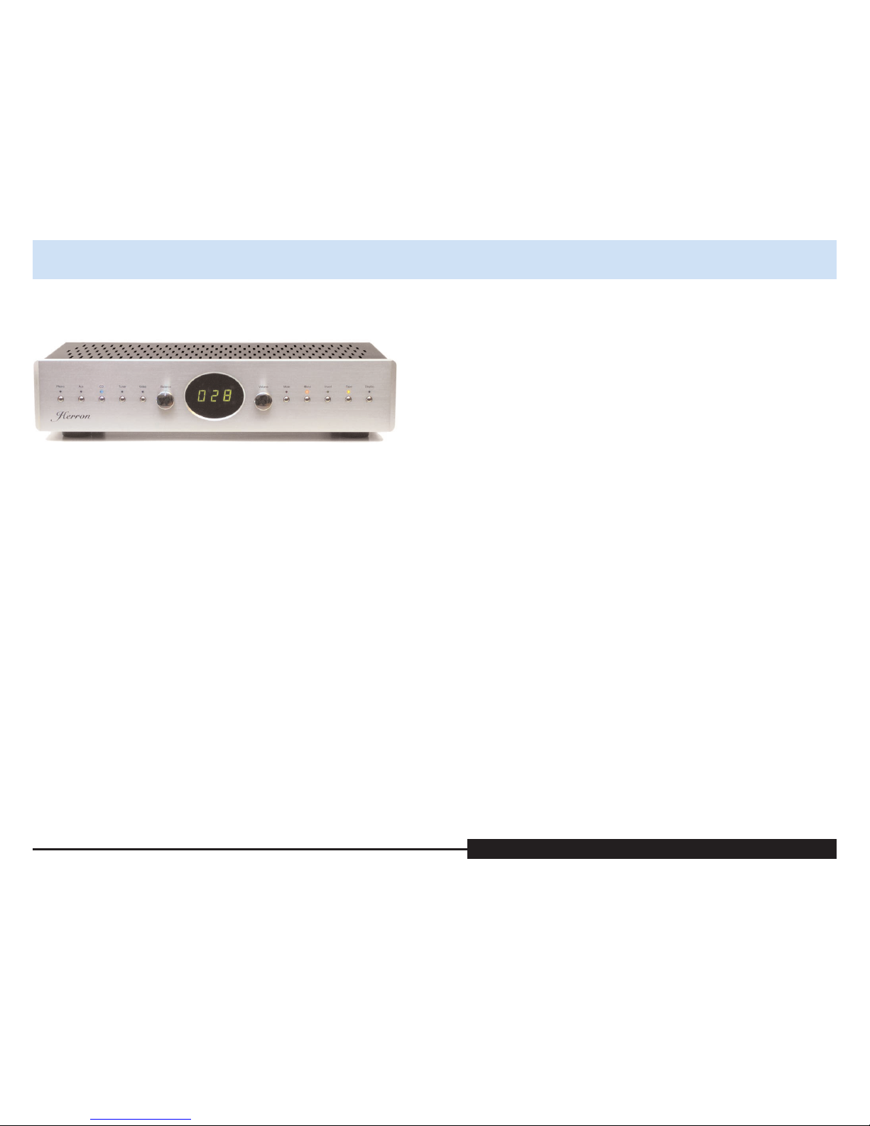
The three-digit volume level display
in the display window at the center of
the front panel indicates the volume
level (0 to 100) and the parameters of
the unit during start-up. It also indi-
cates “PAS” during pass-through mode
and Ldb or Hdb gain modes when the
phono button is pushed.
The selected input is indicated
by the blue lights on the left side of
the front panel.
These inputs are:
• Phono
• Aux
• CD
• Tuner
• Video
The VTSP-3 has two gain modes for
system matching. The VTSP-3 gain
modes can be switched by holding the
phono button in for 2 seconds. The
high gain “Hdb” mode has 12 db gain
and the low gain “Ldb” mode has 6
VTSP-3 Vacuum Tube Stereo Preamplifier Owner’s Manual
Please read the Owner’s Manual completely BEFORE operating the unit.
db total gain. The “Ldb” gain mode is
indicated by a decimal point in the
volume level display window. The
mode “Hdb” or “Ldb” are also indi-
cated in the volume level display
window anytime the phono mode
button is pressed on the front panel or
from the remote control. The Ldb
mode is indicated by a decimal point
in the volume display. The gain can
only be changed from the front panel
phono button and not from
the remote control.
The tape input (loop) indicator is
on the right side of the front panel.
This input can be selected from
either the front panel or the remote
control after the unit has gone
through the start-up sequence.
The balance control provides a full
range of adjustment for relative bal-
ance between the right and left
channels. In the centered position,
each channel is equal in signal sensi-
tivity. Rotating the balance control in
the clockwise direction (to the right)
decreases the volume in the left chan-
nel relative to the right channel.
Rotating the balance control in a
counter-clockwise direction (to the
left) decreases the volume in the right
channel relative to the left. In the
fully clockwise or counter-clockwise
position, the left or right channel
respectively will be muted. Normal
operation is provided when the bal-
ance control is in the centered
position. The “Balance” knob operates
an infinitely variable control that is
barely in the circuit at center position.
Note: The balance control cannot be
operated from the remote.
The “Volume” knob operates a
stepped encoder. Rotating the volume
knob to the right increases the vol-
ume level, or to the left to decrease
the volume level. The level is dis-
played from 0 to 100 in the display
window. The volume can also be
controlled from the remote control.
Note: Since the volume control is a
stepped attenuator the individual
steps of the volume control as it is
raised or lowered may produce
“clicks” for a short period after the
unit, or input device has been turned
on. This will be most noticeable
between steps 29 and 30. These
“clicks” are the result of a D.C. voltage
at the input of the unit causing
instantaneous D.C. level shifts as the
volume control steps up or down.
This condition will usually subside
after a few minutes as the D.C. level at
the input from the source component
dissipates.
The red “Mute” light indicates
that the preamplifier is in mute mode
and no signal will pass through the
unit. During mute, the stepped atten-
uators are set to zero level and the
output is shorted by a relay. The mute
mode can be initiated or disengaged
from the front panel or the remote
control.
The orange “Mono” light indi-
cates that the preamplifier is in
monaural mode. In mono mode, the
unit mixes the left and right signals to
monaural so that the signals coming
from the left and right channels are
the same. Mono mode can be initiated
or disengaged from the front panel or
the remote control.
The amber “Invert” light indi-
cates that the preamplifier is in
phase-inverting mode. The invert
mode reverses the absolute phase of
both channels. The invert mode can
be initiated or disengaged from the
front panel or the remote control.
six seven
Front Panel Features
Front Panel Features
The amber “Tape” light indicates
that the tape input has been selected.
The tape input allows the user to loop
the selected input (source) signal out
from the tape output through a tape
machine or other processor, and listen
to the signal coming back into the
tape input. The tape input mode can
VTSP-3 Vacuum Tube Stereo Preamplifier Owner’s Manual
Please read the Owner’s Manual completely BEFORE operating the unit.
be initiated or disengaged from the
front panel or the remote control.
The blue “Display” light indicates
that the front panel displays are in
dim mode. The display mode can be
initiated or disengaged from the front
panel or the remote control.
Power Line Polarity Switch
This switch selects the power-line
polarity. AC line polarity may affect
performance. The following is the rec-
ommended procedure for determining
the best operation:
• With the mute engaged, set the
power line polarity switch to the
“A” position then disengage the
mute.
• Set the volume control to the
desired level and listen closely to
the quality of the reproduction.
This will be used as a baseline for
determining AC polarity.
• Engage the mute function and
change the AC polarity of the
preamplifier by switching the
power line polarity switch to the
“B” position then disengage the
mute for listening. Repeat the
process, listening to the same
source.
• Place the AC polarity switch in
the position that sounds best. It
may be necessary to change the
AC polarity if you make other
equipment or power connection
changes in your audio system.
Note: The AC polarity switch
should only be operated with the
unit muted.
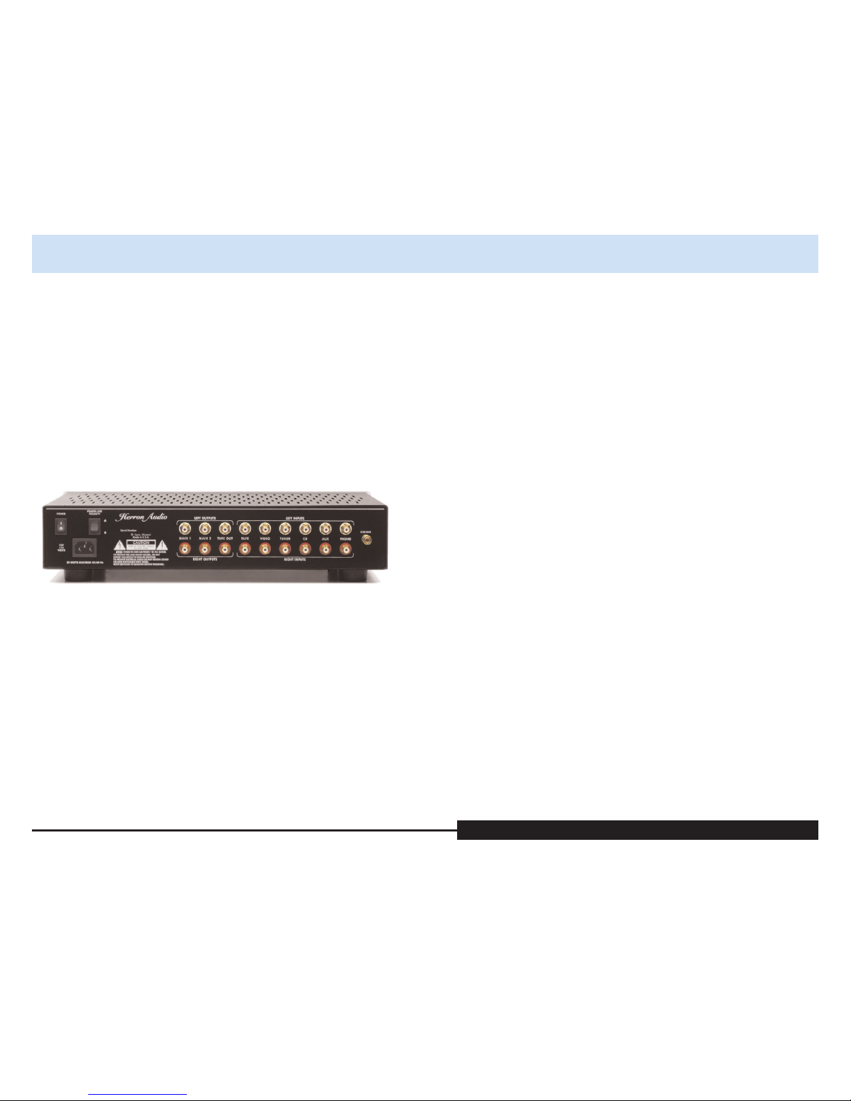
Inputs
The inputs are grouped by channel:
the upper bank contains the left-
channel inputs, the lower contains
the right-channel inputs. The left/
right input pairs are arranged verti-
cally. The input pairs are arranged on
the back in the same order as on the
front panel and remote (with the
exception of the tape loop input).
RCA input plugs should be inserted
firmly into the input jacks while the
unit is powered down. Any individual
ground-bleed connections should be
connected to the gold ground lug
located near the end of the banks of
input jacks.
Outputs
There are two types of outputs in the
VTSP-3. The main outputs are
intended for connection to high-
quality power amplifiers or a multi-
channel electronic crossover. Two
pairs of main outputs are provided so
that users may distribute the audio
signal to multiple amplifiers.
The tape outputs are provided to
allow monitoring of the selected
audio signal after the input relays. The
signal from the tape output corre-
sponds to the input chosen by the
user and displayed on the front panel.
eight nine
Rear Panel Features
Rear Panel Features
The rear panel was designed for
flexibility and ease of access to
less- frequently used functions. The
high-precision RCA input jacks are
gold-plated to minimize signal-
degrading corrosion. The special Teflon
insulation material in the RCA connec-
tors maintains purity of the signal
from the input cable into the unit.
Power Connection
An IEC power cord connector is pro-
vided for attaching either the
factory-provided power cord or
another chosen by the user.
Power Switch
When the unit’s POWER switch is
placed in the on (“up”) position, the
unit is powered up. At power up, the
unit is automatically muted until full
operational capabilities are reached
and the voltages are stable at the
tubes. When the switch is moved to
the off position, the unit is automati-
cally muted and powered down.
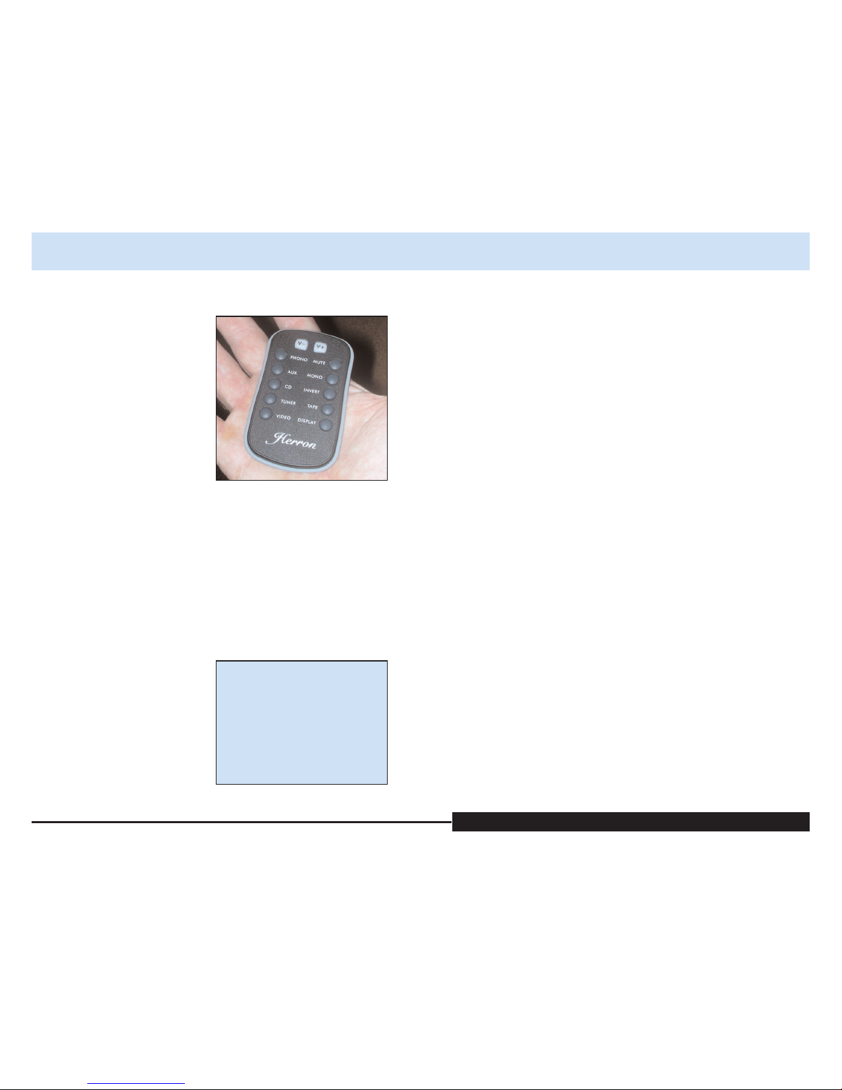
Remote control functions:
• Input Selection
• Absolute Polarity
• Display Brightness
• Volume, Mute, and Mono/Stereo
The remote control is laid out in a
fashion similar to the front panel of
the VTSP-3.
The input controls on the left side
(top to bottom) are in the following
order:
• Phono
• Aux
• CD
• Tuner
• Video
The volume is controlled with the
two white buttons at the top center of
the remote. The Vbutton on the left
decreases the volume. The Vbutton
on the right increases the volume.
The controls on the right side of
the remote (top to bottom) are in the
same order as the front panel:
• Mute
• Mono
• Invert
• Tape
• Display
VTSP-3 Vacuum Tube Stereo Preamplifier Owner’s Manual
Please read the Owner’s Manual completely BEFORE operating the unit.
NOTE: The balance control
cannot be operated from the
remote control.
The remote control will only con-
trol the unit if the top of the remote is
pointed toward the display window of
the VTSP-3. The remote control uses
two CR2025 3-volt lithium batteries.
Operation of the Herron VTSP-3
stereo preamplifier is straightforward.
As with any fine audio component,
careful setup and integration into
one’s system is important for opti-
mum performance, safety, and
reliability. Please read through the fol-
lowing setup instructions completely
prior to operating the unit.
Procedure
1. Position the unit in a well-ven-
tilated area on a firm, stable
surface, away from equipment
that generates alternating mag-
netic fields such as motors,
transformers, etc. Magnetic
fields of this type can introduce
hum into the signal path.
Good ventilation is important
in order to prevent overheat-
ing of the unit. Excess heat will
shorten the life of the unit.
2. Connect the signal cables from
the source components (CD,
phono preamplifier, VCR, tuner,
etc.) to the VTSP-3’s rear panel
jacks, left-to-left and right-to-
right. Connect any ground bleed
wires to the ground connector of
the phono preamplifier.
3. Plug the amplifier and tape
recorder input cables into the
corresponding outputs, left-to-
left and right-to-right.
4. Plug the power cord into the
IEC socket. Make sure it is
firmly seated prior to inserting
the plug into an AC outlet.
5. Plug the power cord into a 115-
volt (U.S. spec units) AC outlet.
6. Power up the source compo-
nents.
7. Power up the VTSP-3 by switch-
ing on the power switch.
8. Once the VTSP-3 is powered up
and operating, power up the
downstream amplifier(s)
and crossover, if any, as
recommended by their manu-
facturers.
9. With the Volume control in the
lowest position, gradually
increase the gain until the
desired level is reached.
10. When the listening session is
complete, it is suggested, but
not required, that the VTSP-3
be powered down after the
crossover, amplifiers, and tape
recorder, and before the source
components.
ten eleven
Installation and Operation
Installation and Operation
NOTE: the indicator on
the batteries must be fac-
ing the back side of
the remote. Installing the
batteries in the wrong
direction may damage
the remote control.
The remote Control
The Remote Control
Power Requirements
It is recommended that the VTSP-3
stereo preamplifier be connected to
the same power source (dedicated cir-
cuit) as the other source components
(phono stage, turntable, CD player,
SACD player, etc.) and power ampli-
fiers in the audio system. This will
reduce the component- to-component
differential RFI (radio frequency inter-
ference) level that will be required to
be conducted by the audio intercon-
nects, which are a very important part
of the audio chain. RFI can add
brightness and lack of clarity to an
audio system.
With the higher definition and
detail available through the VTSP-3,
careful attention to the setup of other
components will yield significant ben-
efits. There may also be considerable
VTSP-3 Vacuum Tube Stereo Preamplifier Owner’s Manual
Please read the Owner’s Manual completely BEFORE operating the unit.
gains from the upgrade of existing
electronics.
We recommend the use of high-
quality interconnecting cables
between the source components and
the VTSP-3, and between the VTSP-3
and components downstream of it
(the power amplifiers and speakers).
Due to the increased definition of
detail, it may be necessary to make
minor adjustments in speaker posi-
tion or active crossover settings to
optimize their performance. We
have determined that minor time
alignment changes in a setup can
produce major advances in the over-
all quality of the reproduced signal,
bringing the listener closer to the
original performance.
We do not recommend changing tube
brands for the purposes of “improving
sonic performance.” Tubes of even the
same part number (6922 in the case of
the VTSP-3) from different manufac-
turers and different production lots
generally vary considerably in many
operating parameters. The Herron
VTSP-3 stereo preamplifier has been
optimized for the tubes that were sup-
plied by the factory. The original
tubes should provide many years of
good performance due to the design’s
conservative plate voltage and current
operating requirements. If replace-
ment tubes are required, Herron
Audio recommends the use of our
factory-matched sets of tubes.
These tubes have been selected for
their superior performance.
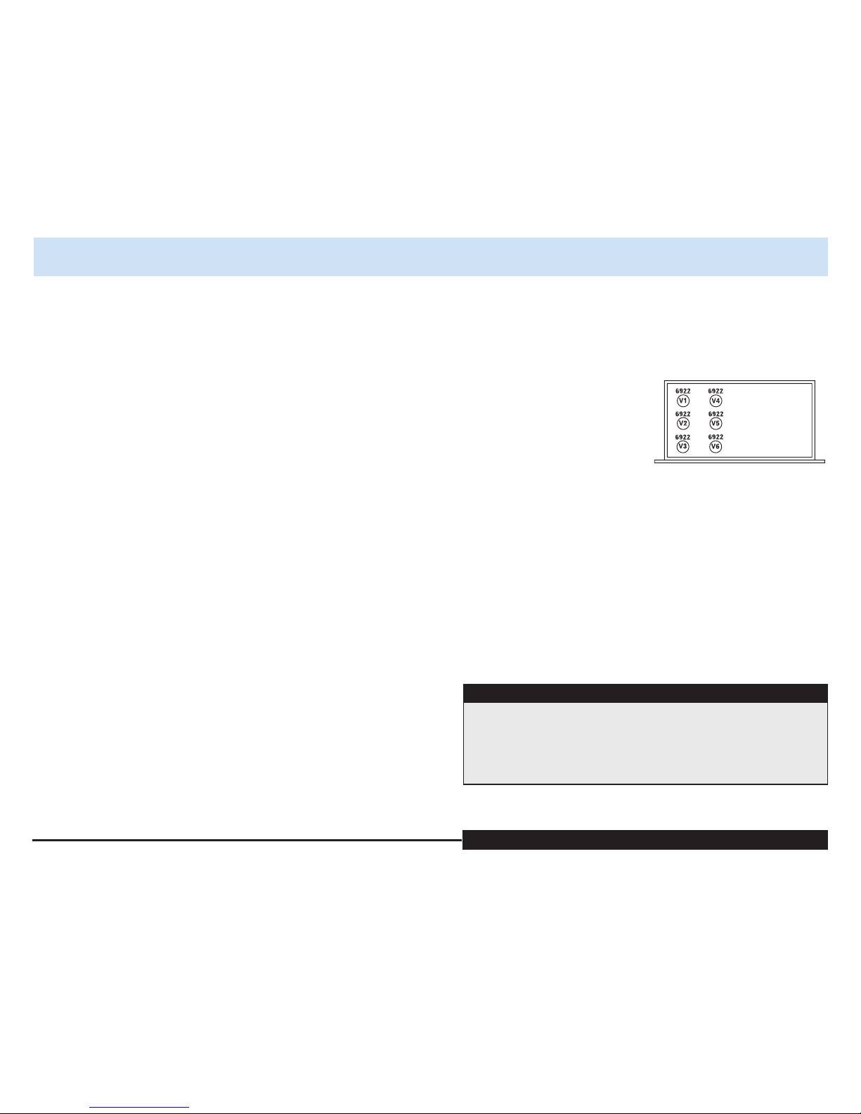
All 6 tubes in the Herron VTSP-3
are of the type 6922.
twelve thirteen
!!!!!
When changing tubes, the VTSP-3 should be unplugged and left off for a
minimum of 30 minutes prior to opening the unit to insure that haz-
ardous voltages in the power supply have time to discharge before
entering the unit.
CAUTION CAUTION CAUTION CAUTION CAUTION CAUTION
Changing Tubes
Changing Tubes
If access to the interior of the pre-
amplifier is necessary, be sure to
install the grounding lug under the
top screw at the rear of the chassis
when reinstalling the cover.
When changing tubes, the VTSP-3
should be unplugged and left off for a
minimum of 30 minutes prior to
opening the unit, to insure that haz-
ardous voltages in the power supply
have time to discharge.

fourteen
Frequency response: 1 Hz to beyond 100 kHz,
20 Hz to 20 kHz /0.1 dB volume at 30
Output impedance: 100 ohms nominal at 1 kHz
Input impedance: 100,000 Ohms
Gain: 12 dB in Hdb mode, 6 dB in Ldb mode
Volume control: 100-position electronic stepped attenuator,
maximum differential 0.1 dB channel
to channel
Absolute polarity: Switchable
Front panel: Available in black or clear anodized aluminum
Tubes: Qty. 6, 6922 dual triodes
Dimensions: 17.6” wide 4” high 10.5” deep
Warranty: 3 years, parts and labor; tube warranty: 90 days
VTSP-3 Vacuum Tube Stereo Preamplifier
Technical Specifications
Technical Specifications
Table of contents
Other Herron Audio Amplifier manuals

Herron Audio
Herron Audio VTSP-2 User manual

Herron Audio
Herron Audio VTSP-1A/166 User manual

Herron Audio
Herron Audio VTPH-1 User manual

Herron Audio
Herron Audio VTSP-3A User manual

Herron Audio
Herron Audio M1A User manual

Herron Audio
Herron Audio M150 User manual

Herron Audio
Herron Audio VTPH-2 User manual

Herron Audio
Herron Audio VTSP-3A User manual

Herron Audio
Herron Audio M1 User manual

Herron Audio
Herron Audio HL-1 User manual


