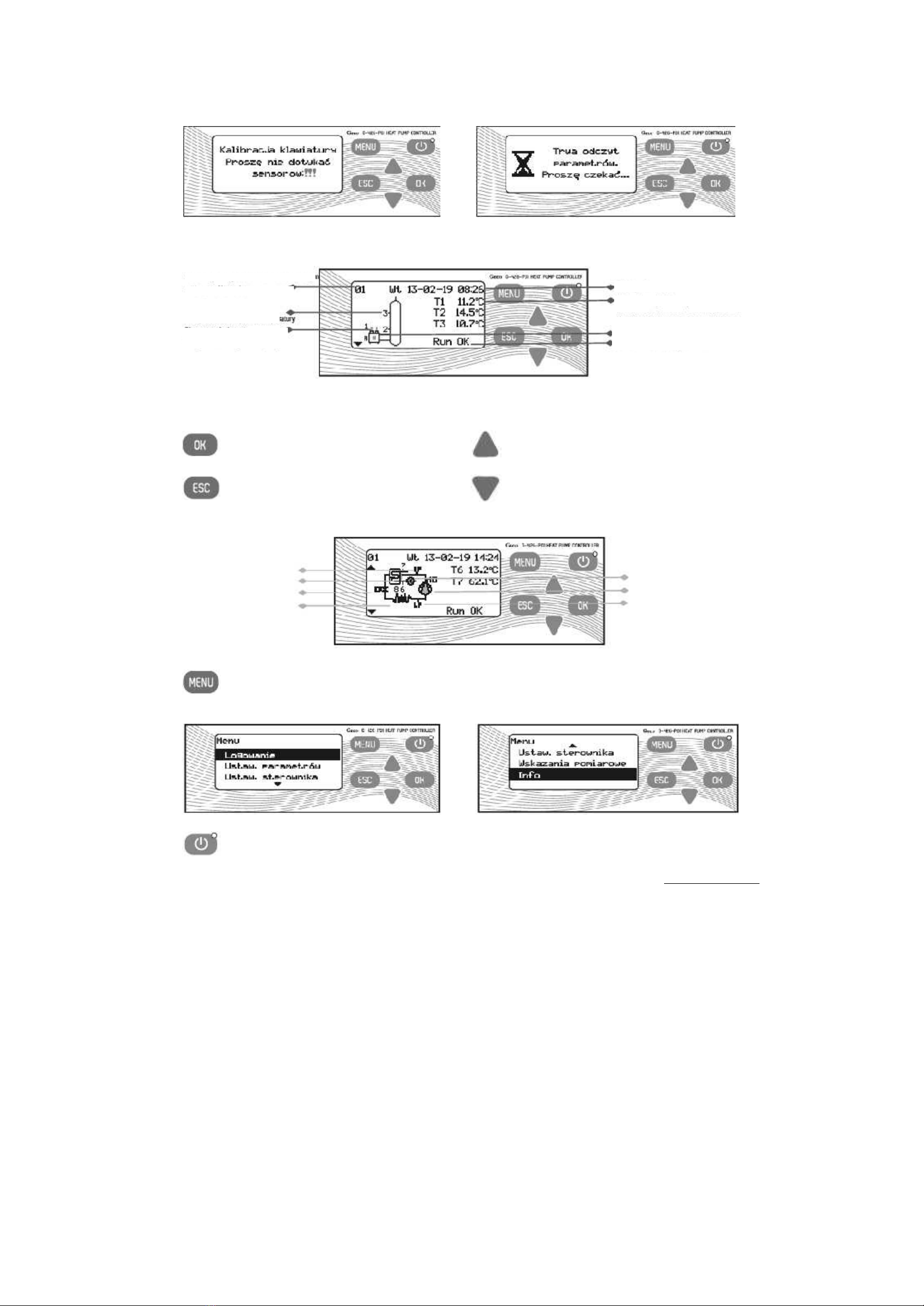
Controller map
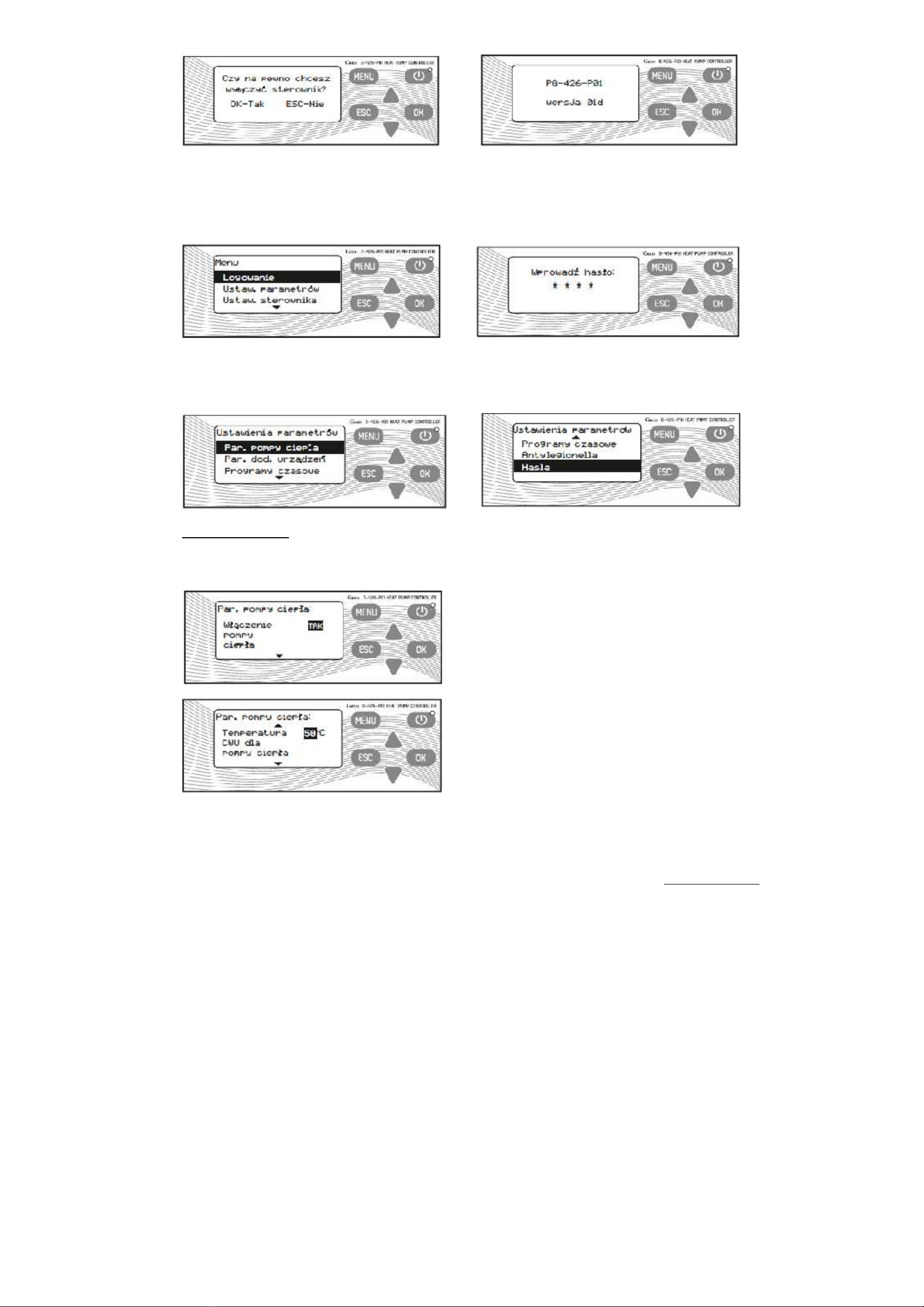
MENU Login [default 0000]
Parameter settings
Heat pump operation parameters
Heat pump activation [YES/NO, factory setting YES]
HUW temperature for heat pump [10-60°C, factory setting 50°C]
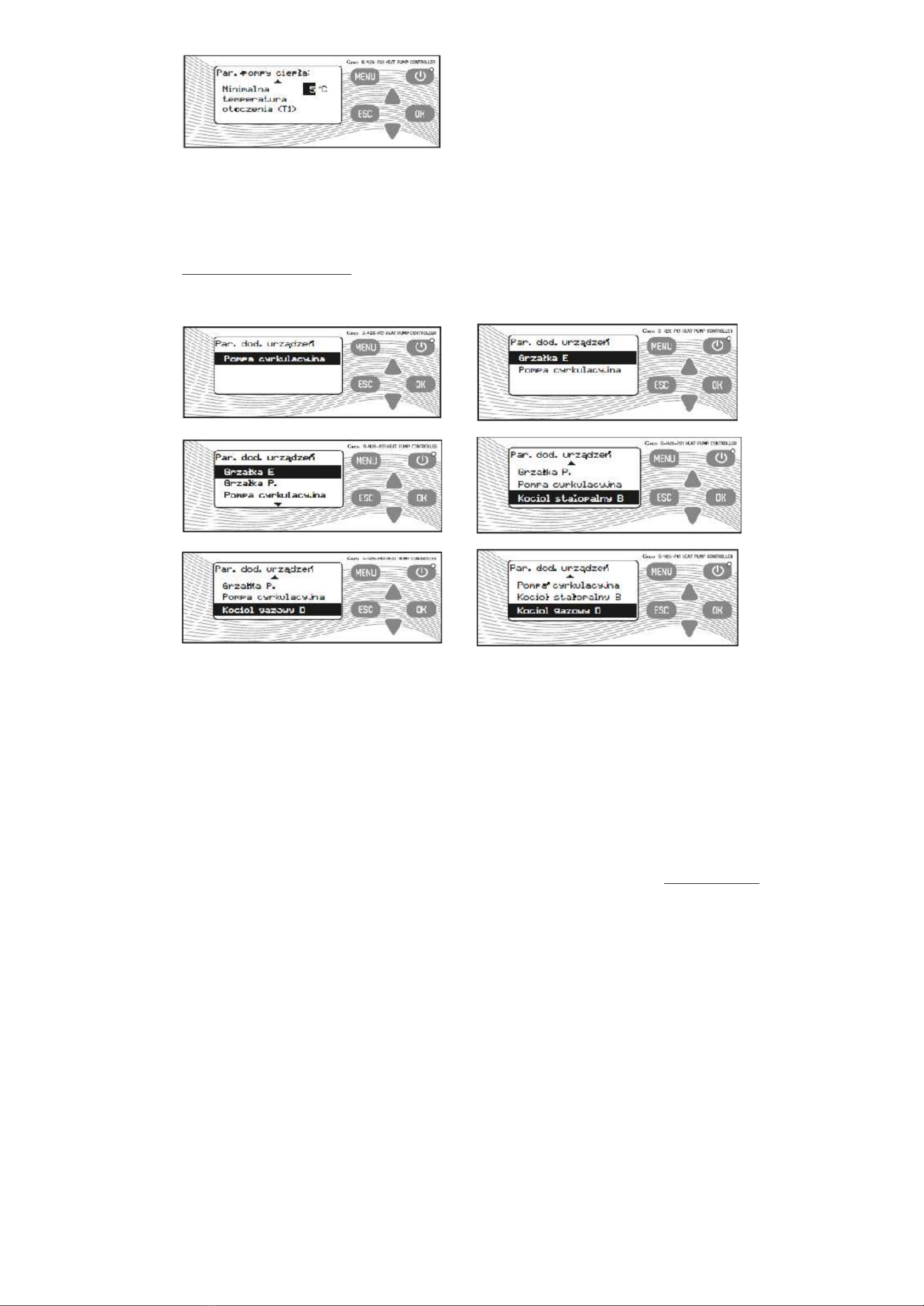
Minimum ambient temperature (T1) [-5-10°C]
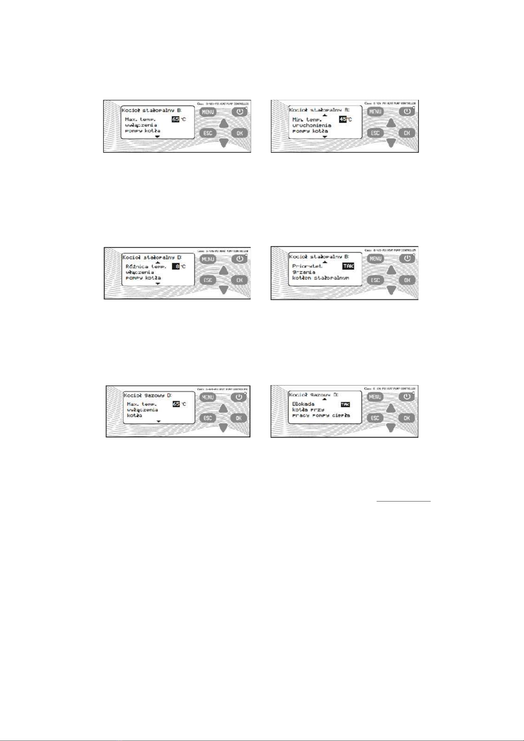
Parameters of accessory equipment
Heater E [shown in diagrams no. 3,4,5,6,7,8,9]
Heater activation [YES/NO, factory setting YES]
HUW temperature for heater - heat pump on [30-60°C, factory setting 45°C]
HUW temperature for heater - heat pump off [30-60°C, factory setting 55°C]
Heater stoppage during heat pump operation [YES/NO, factory setting YES]
Heater stoppage during gas-fired boiler operation [YES/NO, factory setting YES -
shown in diagrams no. 4,7,9]
Heater P [shown in diagrams no. 4,5,6,7,8,9]
Heater activation [YES/NO, factory setting YES]
HUW temperature for heater - heat pump on [30-60°C, factory setting 45°C]
HUW temperature for heater - heat pump off [30-60°C, factory setting 55°C]
Heater stoppage during heat pump operation [YES/NO, factory setting YES]
Heater stoppage during gas-fired boiler operation [YES/NO, factory setting YES -
shown in diagrams no. 4,7,9]
Circulating pump [shown in diagrams no. 2,3,4,6,7,8,9]
Minimum circulating pump activation temperature [20-60°C, factory setting 35°C]
Circulating pump operation mode [INTERMITTENT/CONTINUOUS, factory
setting INTERM.]
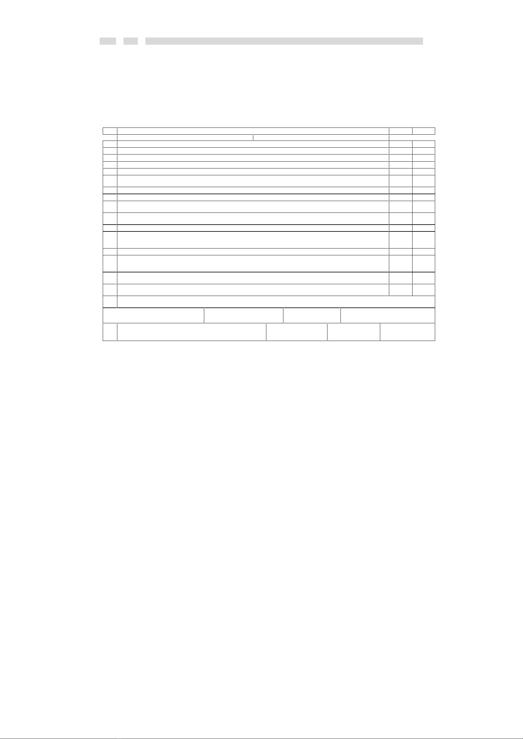
Solid fuel fired boiler B [shown in diagrams no. 5,7,9]
Max. boiler pump deactivation temperature [10-85°C, factory setting 65°C]
Min. boiler pump activation temperature [30-60°C, factory setting 45°C]
Temperature difference for boiler pump activation [5-15°C, factory setting 8°C]
Solid fuel fired boiler heating priority [YES/NO, factory setting YES]
Gas-fired boiler D [shown in diagrams no. 6,7,8]
Max. boiler pump deactivation temperature [10-85°C, factory setting 65°C]
Boiler stoppage during heat pump operation [YES/NO, factory setting YES]
Time programmes
Heat pump
Heater E
Circulating pump [shown in diagrams no. 2,3,4,6,7,8,9]
Gas-fired boiler D [shown in diagrams no. 6,7,8]
Anti-Legionella [shown in diagrams no. 3-9]
Anti-Legionella function activation [YES/NO, factory setting YES]
Protection carried out by heater E [YES/NO, factory setting YES]
Protection carried out by heater P [YES/NO, factory setting YES]
Protection carried out by gas-fired boiler [YES/NO, factory setting YES, shown in diagrams
no. 6,7,8]
Passwords
User
Controller settings
Date and time
Display Backlight brightness [1-10, fab.10]
Inactivity time until backlight switching off [1-10min., factory setting 10min.]
Sounds Sound of keys [YES/NO, factory setting YES]
Sound of alarms [YES/NO, factory setting YES]
Port RS485
Transmission rate [by default 115200]
Physical address [by default 255]
Logic address [by default 65535]
Language
Polish
English
German
Manual control
Measured indications
Info
Software replacement [only for manufacturer]