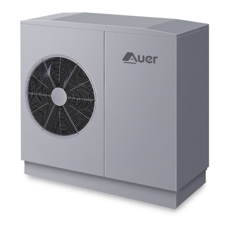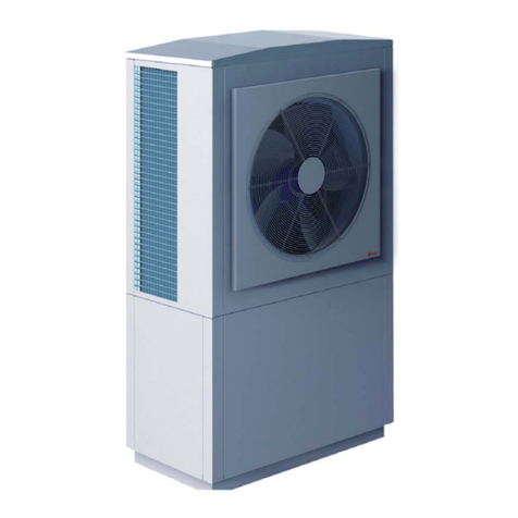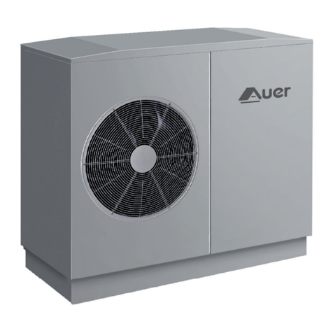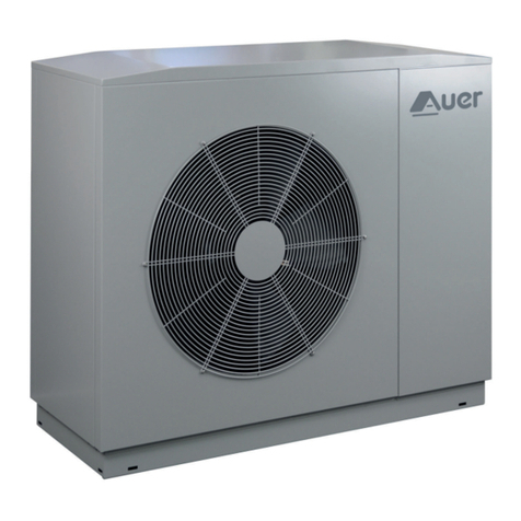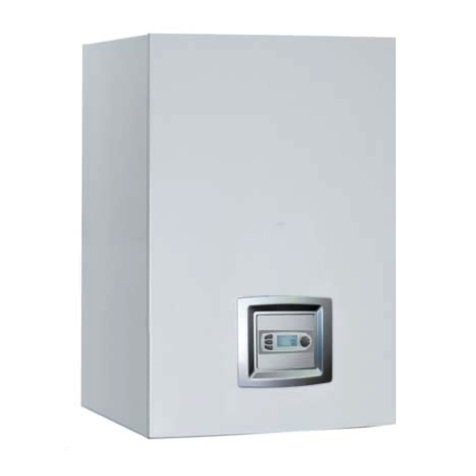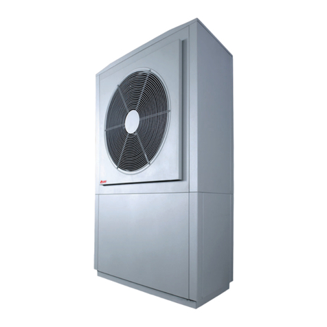
- manual HRC70 PILOT -PREMIUM- /2-
2
TABLE OF CONTENTS
1 PLEASE READ IMMEDIATELY ........................ 3
1.1 - Important information.......................................................................................3
1.2 - Safety advice and instructions........................................................................3
1.3 - Delivery terms and conditions........................................................................ 3
1.4 - Storage and transport........................................................................................ 3
1.4.1 - General information ................................................................................................3
2 INTRODUCTION............................................ 4
2.1 - Standard congurations.................................................................................... 4
2.2 - Operation................................................................................................................4
2.2.1 - Operation of the pilot .............................................................................................4
2.3 - Accessories delivered as standard.................................................................4
2.4 - Accessories available as options ....................................................................5
3 INSTALLATION................................................ 5
3.1 - Wall mounting....................................................................................................... 5
3.2 - Embedding and enclosing ............................................................................... 5
3.3 - Plumbing installation.........................................................................................6
3.3.1 - Plumbing connections of the installation .......................................................6
3.3.2 - Hydraulic connections :
Heat Pump circuit..................................................................................................... 7
3.3.3 - Heat Pump and Pilot pressure-relief valves ....................................................7
3.3.4 - Desludging..................................................................................................................7
3.3.5 - Heat Pump water inlet lter (supplied) ............................................................8
3.3.6 - Heating circuit ........................................................................................................... 8
3.3.6.1 - Flow rate of the heating circuit........................................................... 8
3.3.6.2 - Backow prevention device................................................................. 8
3.3.6.3 - Purging the heating circuit...................................................................8
3.3.6.4 - Insulating the piping .............................................................................. 8
3.3.6.5 - Expansion vessel ...................................................................................... 8
3.3.6.6 - Frost protection and treatment of water.........................................8
3.4 - Installation recommendations depending on the type of
transmitters and on type of usage...............................................................9
3.4.1 - Radiator or fan heating circuit(s) application................................................. 9
3.4.2 - Underoor heating circuit(s) application ........................................................9
3.4.3 -Domestic hot water application...........................................................................9
3.4.4 - Pool application........................................................................................................ 9
3.5 - Electrical control connections.......................................................................10
3.5.1 - Heat Pump control connections.......................................................................10
3.5.1.1 - 2-core sheathed cable..........................................................................10
3.5.2 - Pilot control connections.....................................................................................11
3.5.3 - Ambient temperature control............................................................................12
3.5.3.1 - Installation instructions.......................................................................12
3.5.3.2 - Ambient temperature thermostat...................................................12
3.5.3.3 - Exterior temperature sensor..............................................................12
3.6 - Connecting to the power supply.................................................................12
3.6.1 - Recommendations for connecting the system to the power supply..13
3.6.2 - Connecting the Pilot to the power supply........................................................13
3.6.2.1 - Pilot : 230V single-phase connection .............................................13
3.6.2.2 - Pilot : 400V three-phase connection...............................................14
4 SETUP...........................................................14
4.1 - Control panel.......................................................................................................14
4.1.1 - DIsplay : Symbols and their meaning..............................................................15
4.1.2 - Current functioning display................................................................................15
4.1.3 - Unlocking ..................................................................................................................15
4.1.4 - Language...................................................................................................................15
4.2 - Installer Menu .....................................................................................................16
4.2.1 - Choice of backup corresponding to the installation.................................16
4.2.2 - Configuration of theHRC70 Heat Pump and of the circuits.....................16
4.2.2.1 - Heat Pump model..................................................................................16
4.2.2.2 - Conguring circuit 1.............................................................................17
4.2.2.3 - Circuit 1 ambient temperature control....................................................... 17
4.2.2.4 - Conguring circuit 2.............................................................................17
4.2.2.5 - Circuit 2 ambient temperature control .........................................................17
4.2.3 - settings of operating parameters....................................................................18
4.2.3.1 - Setting the heating curve ...................................................................20
4.2.3.2 - Unrequested set temperature...........................................................20
4.2.3.3 - Set temperature in ECO mode ..........................................................20
4.2.3.4 - Set temperature in FROST PROTECTION mode ..........................................20
4.2.3.5 - Resetting installer parameters to default settings 205 to 230 21
4.2.3.6 - Choice of HRC70 Heat Pump power level ...................................................21
4.2.4 - Manual Forcing of appliance .............................................................................21
5 USE................................................................. 22
5.1 - Setting the date and time...............................................................................22
5.2 - Displaying measured data..............................................................................23
5.3 - User Menu ............................................................................................................23
5.3.1 - Setting the target temperatures.......................................................................24
5.3.1.1 - Setting the AMBIeNCE temperature..................................................24
5.3.1.2 -Setting the ECO temperature...........................................................................24
5.3.1.3 - Setting the target ambient temperature Frost protection...24
5.3.1.4 - Setting the temperature of domestic hot water.........................25
5.3.1.5 - Setting the pool temperature...........................................................25
5.3.2 - Setting a holidayperiod .......................................................................................................25
5.3.3 - Temporary exemption of programmed comfort modes...........................25
5.3.4 - boost mode .............................................................................................................25
5.3.5 - Selecting summer / winter mode ...............................................................................26
5.3.6 - Choosing the LANGUage .....................................................................................................26
5.3.7 - Choice of Beep......................................................................................................................................................26
5.3.8 - Access to the inst. menu...............................................................................................................................26
6 MAINTENANCE AND TROUBLESHOOTING26
6.1 - General information .........................................................................................26
6.2 - Maintenance on the hydraulic circuit.........................................................26
6.2.1 - Water circuit..............................................................................................................26
6.2.2 - HRC70 Pilot .................................................................................................................26
6.2.3 - Maintenance of the heating circuit..................................................................26
6.3 - Maintenance of electrical components...........................................................................................27
6.4 - Checking the operating temperatures ......................................................27
6.4.1 - Access to measured temperatures, internal and external contacts.....27
6.4.2 - Displaying calculated data..................................................................................28
6.4.3 - Consulting the counters.......................................................................................29
6.5 - Errors which are not signalled by error message or alert....................30
6.6 - Alerts and errors which are signalled by the appliance.......................30
6.7 - Error message codes.........................................................................................31
6.7.1 - Errors and solutions...............................................................................................31
6.7.2 - Operation in case of error....................................................................................33
6.8 - Extraction of USB les ......................................................................................35
6.9 - Sensor data curve charts.................................................................................35
6.9.1 - Water inlet and outlet HRC70 Heat Pump and HRC70 Pilot de-icing sensor - air
intake sensor - sensors installed on compressors 1 and 2 - \swimming pool
sensor - DHW sensor..................................................................................................................................35
6.9.2 - Exterior temperature sensor...............................................................................36
6.10 - Decommissioning and disposal.................................................................36
7 LIST OF SPARE PARTS.................................. 37
8 WARRANTY ................................................... 38
8.1 - Limitations of warranty....................................................................................38
8.1.1 - General information ..............................................................................................38
8.1.2 - Cases (not limited to) for exclusion from warranty....................................38
8.1.2.1 - Heating cicuit water..............................................................................38
8.1.2.2 - Handling....................................................................................................38
8.1.2.3 - Installation site........................................................................................38
8.1.2.4 - Electrical connections ..........................................................................38
8.1.2.5 - Hydraulic connections .........................................................................38
8.1.2.6 - Accessories...............................................................................................38
8.1.2.7 - Maintenance............................................................................................38
APPENDICES...................................................... 39
A1 - Dimensions ...............................................................................................................39
A2 - Technical specications ........................................................................................39
A2.1 - HRC70 Pilot...................................................................................................39
A3 - Frost protection .......................................................................................................39
A4 - Sizing the expansion vessel.................................................................................40
A5 - Programming the heating modes ....................................................................40
A5.1 - Create a program......................................................................................41
A5.2 - Copy existing programming ................................................................42
A5.3 - Modifying a program..............................................................................42
A5.4 - See programming....................................................................................43
A6 - Treatment of the water in the heating circuit...............................................43
A6.1 - Preparing the hydraulic circuit (rinsing)...........................................43
A6.2 - Filling water...............................................................................................43
A6.3 - Treatment of the heating circuit.........................................................43
A6.4 - Protection from freezing........................................................................44
Hydraulic schematic diagram -1 RADIATOR CIRCUIT- -pool possible- ........45
Hydraulic schematic diagram -1 UNDERFLOOR HEATING CIRCUIT- -pool
possible-...................................................................................................................46
Hydraulic schematic diagram -2 RADIATOR CIRCUITS- -pool possible-......47
Hydraulic schematic diagram -2 UNDERFLOOR HEATING CIRCUITS- -pool
possible-...................................................................................................................48
Hydraulic schematic diagram -1 RADIATOR CIRCUIT + DHW- -pool
possible-...................................................................................................................49
Hydraulic schematic diagram -1 RADIATOR CIRCUIT + POOL-......................50
Hydraulic schematic diagram -1 POOL CIRCUIT + DHW-.................................51
Hydraulic schematic diagram -1 DIRECT CIRCUIT and 1 MIXED CIRCUIT-..52
with optional 2nd circuit at a lower temperature (Ref.751014) -pool possible-
52
Hydraulic schematic diagram -2 DIRECT CIRCUITS and 3rd MIXED CIRCUIT-..
53
with optional 2nd circuit at a lower temperature (Ref.751014) .......................53
and optional 2-way motorised valve for 1st direct circuit (Ref. 740022) -pool
possible-...................................................................................................................53
HRC70 Pilot electrical schematic diagram ................................................................54
HRC70 Pilot internal wiring schematic diagram .....................................................58


