Hewalex PCWU 2.5kW User manual
INSTRUCTIONS FOR FITTER
NAME cat. no. HEWALEX: 91.10.13 PCWU 2.5kW
EQUIPMENT CHARACTERISTICS
Utility water heat pump - PCWU 2.5kW uses heat contained in outdoor or
ventilation air for high-efficiency hot utility water production.
The temperature of outlet air from heat pump is 5-10°C lower. It may be
used to cool rooms in summertime.
Heat pump PCWU 2.5kW is a complete unit, which is very easy to install. The following tools and accessories will
be needed for fitting:
- Philips screwdriver PZ2
- flat-head power screwdriver 2mm
- flat wrenches 17, 27, 41
- welding machine in case of PP tubes
- drilling machine with drill fitted for building wall, in order to fasten
heat pump holder in a stable way
- drill rig ND150 in case of air-ducts going outside building (option,
possibility to apply other technologies)
- on-wall fixing grip with dowels fitted for building wall (option)
- 3 cut-off valves
- 2 drain valves
- water filter
- water tube, min. diameter Φ20mm inside, insulated (recommended:
plastic)
- air tube (depending on an installation, additionally: ducts, choke
valves, air guides)
- masking cover for ventilation ducts going outside building
- 4-wire cable 0.75mm², to extend controller if needed
- protective pipe to cover controller cable
- pipe unions and gaskets for circulating pump
- check valve (when pump has shared stub pipe for return to the tank
with circulation)
- pipe unions and nipples GZ 3/4" for screwing-in in heat pump
(easily removable)
- a hose to extend condensate discharge
- thread packing (e.g. hemp fibres, Teflon thread)
NOTE: The tools and equipment listed above include those most frequently used in installations. Each installation
may have its individual requirements, which would make it necessary to apply other tools and extra accessories.
Table of Contents
Also read User’s Instructions prior to fitting!
1. Storage and handling .................................................................................. 2
2. Choosing installation location ...................................................................... 2
3. Installation ................................................................................................... 4
4. Maintenance .............................................................................................. 10
5. Heat pump safeguards ............................................................................... 11
6. The unit cut-off from power system ........................................................... 12
7. Controller description (extended version for fitter) .................................... 12
8. Alarms review. ............................................................................................ 16
9. Controller messages review ...................................................................... 17
Technical data
Dimensions . .................................................................................................. 18
Technical parameters list ............................................................................... 19
Wiring diagram. ............................................................................................. 20
Guarantee certificate ................................................................................... 21
Checklist (for fitter) ....................................................................................... 22
FITTER

1
Storage and handling
During storage heat pump should be protected by foil and original factory cardboard packaging. Equipment
storage temperature should range within -10 to 45°C. The unit cannot be flooded with water during storage.
Heat pump should be carried at angle up to 60°. After handling heat pump should be left in its normal
position for 1 hour before it is started up.
While transporting heat pump on a cart or with a forklift, it should
be set on a pallet.
2
Choosing installation location
The unit is fitted for building-in only in heated rooms.
Drawn air temperature should range within -5 to 43°C. Quicker heat pump wear and tear will take
place in case of operation at lower or higher temperature values.
Condensate discharge should be extended with a conduit or pipeline to floor drain. Water seal
should be provided within this line in order to avoid fetid odours. One should remember that
condensate discharge flow is generated by gravity only. Level the unit to make condensate flow
down smoothly.
In case of vertically connected air tubes, minimum height from heat pump base to ceiling: 650 mm.
Ducts should be easily removable (that is it should be possible to lift them up to at least 100 mm).
In case of air ducts with horizontal outlet it is necessary to use 90° elbows with tube diameter
160 mm. In that case, minimum room height is 850 mm. should be easily removable (that is it
should be possible to lift them up to at least 100 mm).
Air guides should be provided in case if air is drawn and exhausted from room, where heat pump
is installed. Minimum cubic capacity of room is 80 m3, and it should be provided with very good
ventilation - in this case unit efficiency is worse due to air mixing.
T of air
inlet
0-40°C
Level
Condensate

The surface, where heat pump is installed, must carry the unit weight (64 kg).
It is not allowed to install the unit in rooms, where flammable materials are stored, or in locations,
where drawn air would contain flammable substances. Failure to follow this instruction may result
in fire.
Heat pump cannot be supplied with air or installed in places, where toxic or caustic substances are
present. This also applies to air drawn from pool chlorination facilities, where high chlorine
concentration may cause evaporator perforation.
If air drawn into heat pump contains plenty of fat (e.g. excess of heat from industrial kitchens) fume
hood should be provided with carbon type filters so as to reduce evaporator clogging with fats.
For the same reason, drawn air should be free from dusts.
Connection to mechanical ventilation
In case of the PCWU 2.5kW heat pump, it is possible to connect the pump to mechanical ventilation.
If air handling unit has delivery reaching 350-500 m3/h, it will be fully sufficient source of air for heat pump. Moreover,
solution using ventilation allows efficient air cooling in summertime - by ca. 5-10°C relative to inlet air (cooling
temperature to a large extent depends on fan delivery - at 350m3/h air will be flowing through evaporator longer, and thus
it will be cooler).
Example diagram showing connection to air handling unit - differences may appear depending on the system of air
handling units from various manufacturers.
Wintertime - the pump takes exhaust heat just after air handling unit. We work with air precooled in a recuperator.
However, exhaust air temperature is still high and interesting for us from point of view of heat recovery in a heat pump.
Air cooled in a heat pump is exhausted outside building.
Summertime - heat pump yeses air from outside - exhausts cooled air into a room. This time, air is taken from outside
because due to hygienic requirements we are not allowed to work in a closed cycle.
When connecting heat pump to air handling unit, it is possible to use control system leaving heat pump. We can use
voltage signal (230 V) from the RL01 relay to switch on RL01 air handling unit.
Fats
Dusts
Summertime
air supplied
into room
Choke valve with by-pass
(ventilation tee)
switched to cooling
flap
removed
air
outside
air
air blown off
from room
Wintertime
air supplied
into room
Choke valve with by-pass
(ventilation tee)
switched to cooling
removed
air
outside
air
flap
air blown off
from room

Control may be also solved by way of modifying heat pump and ventilation system operation times. Time interval should
be set in air handling unit guaranteeing that heat pump has suitable air delivery all the time. In case if air handling unit
switches off earlier, heat pump fan will not be capable of overcome installation resistance, and thus air flow through
evaporator will decrease considerably. Low pressure alert may be activated in boundary conditions.
3
Installation
Connection of heat pump and other equipment
Depending on selected diagram and heat pump model, we are able to connect accessory equipment defined as follows
in the controller:
B - solid fuel fired boiler (e.g. coal boiler, fireplace with water jacket)
C - circulating pump
D - automatic boiler (e.g. gas-fired, oil-fired or electric)
E - electric heater
P - electric heater
F - pump for solid fuel fired boiler
Heat pump should be connected to the tank using tubes with the following diameters (inside diameter Ø20 and fittings
3/4", max. distance to the tank: 20 m):
•32x5.4 (in case of PP)
•22x1 (in case of copper)
The system should have possibly lowest resistance, so as to ensure the flow of 0.65m3/h. In order to check if the flow is
correct, we may measure heat pump water inlet and outlet temperature using an external temperature sensor.
Temperature difference between inlet and outlet cannot exceed 5°C.
Equipment connection to heat pump automatics
Unscrew grey cover (7 screws, PZ2 screwdriver). Lift the cover.
After removal of heat pump grey cover it is necessary to unscrew black metal plate protecting electric box (4 screws).
Precise control board wiring diagram is provided at the end of this Manual.
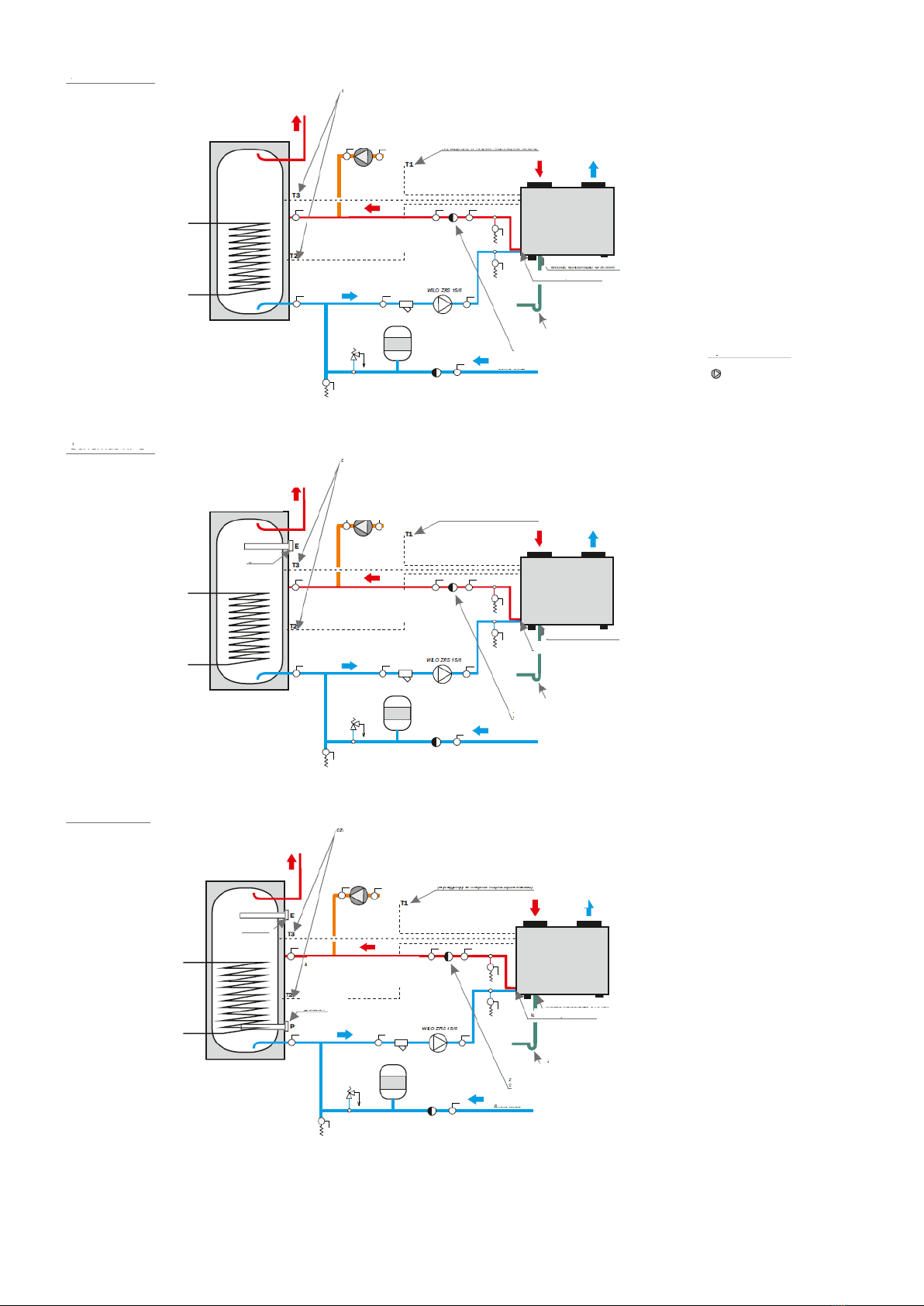
diagram no. 1
hot water
HUW tank
temperature sensors
in the tank
air inlet temperature sensor
(brought to the point, where duct starts)
air
insulated tube inside diam.
min. Φ20 mm up to 10m
max. length each way
condensate stub pipe
Φ16 mm
internal stub pipes 3/4"
discharge to sewage
system with water seal
cold water
Symbols:
The T1 sensor, marked as ambient sensor, is connected to S01
terminals. The sensor is installed in vicinity of heat pump air
inlet. It should be placed outside the building (if air is drawn from
outside) in provided plastic housing.
Temperature sensors T2 (tank bottom) and T3 (tank top) should
be installed according to the diagram and sensor identifiers in
lower and upper part of utility water tank. The sensors are fitted
inside the unit.
Circulating pump (WILO) also should be connected
according to the diagram to OUT H in grey block (above
power supply) marked with white circle in the Photo above. This
pump has been fitted under grey cover of heat pump.
Peripheral equipment or other temperature sensors should be
connected directly to electric board, or to an external strip
(marked with white circle in the Photo above).
drain valve
cut-off valve
expansion vessel min. 4% of tank volume
check valve
water filter
safety valve, max. 7 bar
Precise control board wiring diagram is provided at the end of this Manual.
diagram no. 2
hot water
HUW tank
temperature sensors
in the tank
air inlet temperature sensor
(brought to the point, where duct starts)
air
insulated tube inside diam.
min. Φ20 mm up to 10m
max. length each way
.
condensate stub pipe Φ16 mm
internal stub pipes 3/4"
discharge to sewage
system with water seal
cold water
Symbols:
Circulating pump may be connected to terminals in electric
board - R L02 (OUT C).
Circulating pump with power exceeding 100W must be
powered via a relay.
circulating pump
check valve preventing circulation flow
through heat pump
circulating pump -
C
diagram no. 3
hot water
HUW tank
temperature sensors
in the tank
air inlet temperature sensor
(brought to the point, where duct starts)
air
insulated tube inside diam.
min. Φ20 mm up to 10m
max. length each way
condensate stub pipe Φ16 mm
internal stub pipes 3/4"
discharge to sewage
system with water seal
cold water
Electric heater at tank top should be connected to terminals
RL13 (OUT EH) in electric board.
Electric heater with power exceeding 1500W must be
connected via a relay.
Circulating pump may be connected to terminals in electric
board - R L02 (OUT C).
Circulating pump with power exceeding 100W must be
powered via a relay.
check valve preventing circulation flow
through heat pump
circulating pump -
C
heater E
diagram no. 4
hot water
HUW tank
temperature sensors
in the tank
air inlet temperature sensor
(brought to the point, where duct starts)
air
insulated tube inside diam.
min. Φ20 mm up to 10m
max. length each way
condensate stub pipe Φ16 mm
internal stub pipes 3/4"
discharge to sewage
system with water seal
cold water
Electric heater at tank bottom should be connected to
terminals RL08 (OUT FH) in electric board.
Electric heater with power exceeding 100W must be connected
via a relay.
Electric heater at tank top should be connected to terminals
RL13 (OUT EH) in electric board.
Electric heater with power exceeding 1500W must be
connected via a relay.
Circulating pump may be connected to terminals in electric
board - R L02 (OUT C).
Circulating pump with power exceeding 100W must be
powered via a relay.
check valve preventing circulation flow
through heat pump
circulating pump -
C
heater E
heater P

1. Operation of an external boiler control unit (normally open bridge) only through a relay.
Precise control board wiring diagram is provided at the end of this Manual.
diagram no. 5
hot water
HUW tank
temperature sensors
in the tank
air inlet temperature sensor
(brought to the point, where duct starts)
air
insulated tube inside diam.
min. Φ20 mm up to 10m
max. length each way
condensate stub pipe
Φ16 mm
internal stub pipes 3/4"
discharge to sewage
system with water seal
cold water
Pump for solid fuel fired boiler should be connected to R L
09 (OUT P) in electric board.
Circulating pump with power exceeding 100W must be
powered via a relay.
Temp. sensor T4 should be installed at boiler output.
Electric heater at tank bottom should be connected to
terminals RL08 (OUT FH) in electric board.
Electric heater with power exceeding 100W must be connected
via a relay.
Electric heater at tank top should be connected to terminals
RL13 (OUT EH) in electric board.
Electric heater with power exceeding 1500W must be
connected via a relay.
Circulating pump may be connected to terminals in electric
board - R L02 (OUT C).
Circulating pump with power exceeding 100W must be
powered via a relay.
check valve preventing circulation flow
through heat pump
circulating pump -
C
heater E
heater P
boiler pump - F
Solid fuel fired boiler - B
diagram no. 6
hot water
HUW tank
temperature sensors
in the tank
air inlet temperature sensor
(brought to the point, where duct starts)
air
insulated tube inside
diam. min. Φ20 mm
up to 10m max.
length each way
condensate stub pipe
Φ16 mm
internal stub pipes 3/4"
discharge to sewage system with
water seal
cold water
Automatic boiler (e.g. gas-fired) should be connected to RL
10 (OUT D) in electric board. It is a voltage contact.
1. Operation of an external boiler control unit (normally open
bridge) only through a relay.
2. Control with properly selected resistors instead of HUW [hot
utility water] temperature sensor in the boiler.
Electric heater at tank bottom should be connected to
terminals RL08 (OUT FH) in electric board.
Electric heater with power exceeding 100W must be connected
via a relay.
Electric heater at tank top should be connected to terminals
RL13 (OUT EH) in electric board.
Electric heater with power exceeding 1500W must be
connected via a relay.
Circulating pump may be connected to terminals in electric
board - R L02 (OUT C).
Circulating pump with power exceeding 100W must be
powered via a relay.
check valve preventing circulation flow
through heat pump
circulating pump -
C
heater E
heater P
automatic boiler - D
Electric board
Relay
External control unit in an automatic boiler

2. Control with properly selected resistors instead of HUW [hot utility water] temperature sensor in the boiler.
Exemplary chart of temperature sensor resistances for various boiler manufacturers.
Boiler manufacturer
(example)
R1 resistor [kll]
Temp.: 20 ÷ 30°C
R2 resistor [kΩ]
Temp.: 70 ÷ 80°C
Boiler manufacturer
(example)
R1 resistor [kll]
Temp.: 20 ÷ 30°C
R2 resistor [kΩ]
Temp.: 70 ÷ 80°C
Acv
12.0 ÷ 15.0
1.5 ÷ 2.0
Brotje Heizung
8.0 ÷ 12.5
1.2 ÷ 1.7
Ariston
8.0 ÷ 12.0
1.5 ÷ 2.0
Buderus
8.0 ÷ 12.5
1.2 ÷ 1.7
Beretta
9.0 ÷ 14.0
1.8 ÷ 2.0
De-Dietrich
10.0 ÷ 15.0
1.8 ÷ 2.3
Ferolli
8.0 ÷ 12.5
1.2 ÷ 1.7
Vaillant
3.5 ÷ 3.3
0.4 ÷ 0.6
Junkers
10.0 ÷ 14.8
1.9 ÷ 2.4
Viessmann (new boilers)
9.0 ÷ 15.0
1.5 ÷ 1.8
Stiebel Eltron
10.0 ÷ 15.0
1.0 ÷ 1.5
Viessmann (old boilers)
0.54 ÷ 0.56
0.64 ÷ 0.66
Termet
10.0 ÷ 11.0
1.4 ÷ 1.8
Wolf
5.0 ÷ 7.0
1.8 ÷ 2.6
Precise control board wiring diagram is provided at the end of this Manual.
Electric plate
Relay
HUW sensor of an automatic boiler
diagram no. 7
hot water
HUW tank
temperature sensors
in the tank
air inlet temperature sensor
(brought to the point, where duct starts)
air
insulated tube inside diam.
min. Φ20 mm up to 10m
max. length each way
condensate stub pipe
Φ16 mm
internal stub pipes 3/4"
discharge to sewage system with
water seal
cold water
Automatic boiler (e.g. gas fired) should be connected as
shown in diagram no. 6.
Solid fuel fired boiler should be connected as shown in
diagram no. 5.
Other equipment (if it is to be connected, it should be done as
shown in previous diagrams).
check valve preventing circulation flow
through heat pump
circulating pump -
C
heater E
heater P
automatic boiler - D
solid fuel fired boiler - B

Exact control board wiring diagram is provided at the end of this Manual.
diagram no. 8
hot water
HUW tank
temperature sensors
in the tank
air inlet temperature sensor
(brought to the point, where duct starts)
air
insulated tube inside diam.
min. Φ20 mm up to 10m
max. length each way
condensate stub pipe Φ16 mm
internal stub pipes 3/4"
discharge to sewage system with
water seal
cold water
Solar thermal collectors are operated via solar controller.
It is possible to connect heat pump controller to solar controller
and operate it as a master controller (depending on solar
controller version).
Other equipment, if it is to be added to the system, it should be
connected as shown in previous diagrams.
check valve preventing circulation flow
through heat pump
circulating pump -
C
heater E
heater P
automatic boiler - D
solar thermal
collectors
diagram no. 9
hot water
HUW tank
temperature sensors
in the tank
air inlet temperature sensor
(brought to the point, where duct starts)
air
insulated tube inside diam.
min. Φ20 mm up to 10m
max. length each way
condensate stub pipe Φ16 mm
internal stub pipes 3/4"
discharge to sewage system with
water seal
cold water
Solar thermal collectors are operated via solar controller.
It is possible to connect heat pump controller to solar
controller and operate it as a master controller (depending on
solar controller version).
Other equipment, if it is to be added to the system, it should
be connected as shown in previous diagrams.
In this diagram, solid fuel fired boiler should be is controlled
by the T3 sensor in place of the T2 in previous diagrams.
check valve preventing circulation flow
through heat pump
circulating pump -
C
heater E
heater P
solid fuel fired boiler - B
solar thermal
collectors

Supply air delivery
Minimum 350 m3/h air stream must be guaranteed in order to reach optimal operating parameters. For this purpose,
using air ducts of the same diameter as stub pipes in heat pump - ND150, the sum of two straight sections of air supply
and exhaust duct cannot exceed 10m. Flow resistance for a 90° elbow is the same as for 2m of straight section length. In
a conventional connection, when 90° elbows are provided both in intake and exhaust duct, maximum distance from
building wall is 2m. When heat pump location requires longer air ducts to be connected, a supporting fan or duct of larger
diameter must be installed. When we use smooth reducer, 1m of an ND150 duct may be replaced with 3m of an ND200
duct or 22m of an ND300 duct. The proposed selection of duct lengths and diameters applies to smooth pipes. Choke
valve (ventilation tee) turned to side position has the same resistance as 90° elbow, therefore we have 3 running metres
of duct left to use.
In case of using a duct made of spiral ventilation tube, ND150, maximum length of ducts is 5m each way.
All connections should allow easy disassembly.
Inlet air route should be provided with filter screen catching dusts and larger impurities. The filter should be regularly
cleaned. Filter soiling results in restricted air flow, which in turn deteriorates heat pump efficiency.
Extended ventilation set.
HEWALEX offer includes connection accessories.
Electric power supply
Heat pump should be powered with single-phase current 230V. Connect original power cable to an electric socket (cable
feeding the socket: min. 2.5mm2) with correctly made earthing (earthing resistance should not exceed 4Q). Remember
that the so-called neutralisation is not a correctly made protective zero.
The system itself should be protected with a B16 or C16 fuse.
Due to safety reasons, the installation should be protected by a 30mA residual current device.
Condensate discharge
Condensing steam from cooled air must be discharged into floor drain. Discharge line can be made using rubber hose
supplied in the set, or e.g. of any rubber hose if longer conduit is needed. Condensate discharge stub pipe has a 3/4"
coupler. Condensate discharge flow is generated by gravity only; therefore the system must allow free gravity flow. When
condensate discharge is connected with sewage system, water seal should be used in order to avoid fetid odours.
Condensate volume depends on air cooling scale and its humidity - few litres of condensate may be generated during
one-time tank heating. Condensate line stub pipe outside diameter is Φ16mm, and rubber discharge hose should have
the same inside diameter.
External control
The unit may be operated using an external control unit. In the strip, terminals marked ‘External control unit’ are
connected by a bridge. The Ext OFF message will be displayed in right bottom corner after their disconnection. The
‘External control unit’ option of the controller allows defining, which heating devices are to be operated by the external
control unit.
4
Maintenance
Supply ducts and air filter
Air filter cleaning should pose no problems. Supply air line should be provided with a filter at air inlet to the heat pump.
The filter should be checked and cleaned if necessary at 2-3 month intervals. Filter soiling will result in air flow choking,
which leads to drop in heat pump efficiency.
Cleaning of air ducts is very important, especially when using cooler air for room chilling. In that case it is required to
clean ducts once in 2 years using antibacterial preparations for air conditioning duct cleaning. Bacteria or fungi will
appear inside the ducts if water penetrates into them. Moisture may also appear inside the ducts if flowing air is warmer
than environment (e.g. air drawn from outside, and the unit installed in the basement) - insulation of air ducts reduces the
risk of steam condensation.
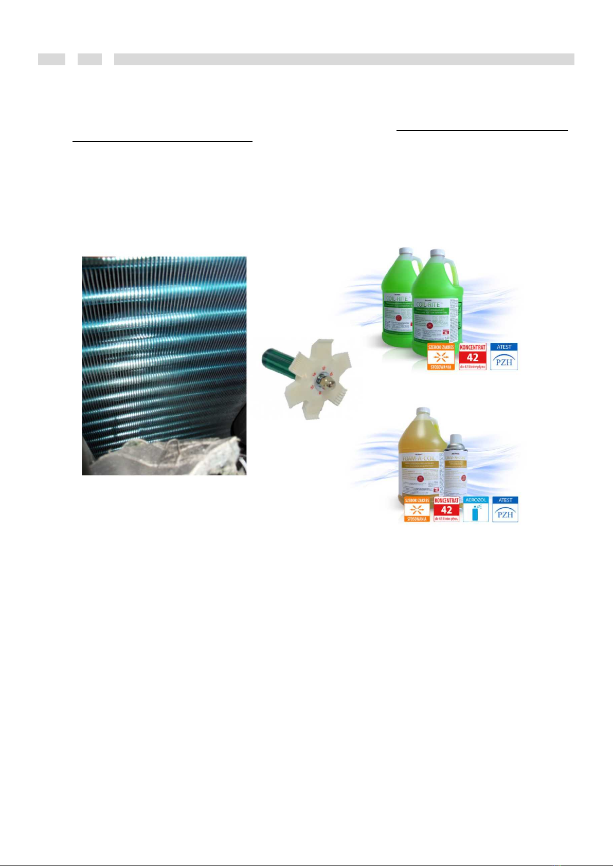
Housing removal and evaporator cleaning
Depending on evaporator soiling type:
- in case of dust and spider’s web - it is possible to remove them with vacuum cleaner;
- in case of fats clinging to evaporator, apply cleaning agents (e.g. Coil-Rite or Foam-A-Coil).
Evaporator should be cleaned in order to remove bacteria and fungi at least once per 2 years, especially in case of using
heat pump exhaust air for room chilling (e.g. using Coil Disinfectant).
Cleaning of scaled exchanger
After few months of the system operation in highly mineralised water environment it is possible that heat pump work
efficiency deteriorates (in an extreme case it will be signalled by high pressure error). Heat pump exchanger cleaning is
required then.
1) Close cut-off valves at the heat pump;
2) “Short-circuit” the system using drain valves;
3) Pour into “short” system a solution of agent used for descaling of e.g. kettles (KAMIX or alike);
4) Close short cycle and switch on heat pump;
5) Heat medium in the cycle to 60°C;
6) Release the solution and wash the pipeline;
7) Connect to primary cycle.

5
Heat pump safeguards
Evaporator defrosting mode
Evaporator defrosting indicates the state, in which heat pump removes ice from the
evaporator. Ice in evaporator disturbs and reduces air flow, which in turn decreases the
uptake of free heat and additional working load for compressor.
Defrosting depends on the indications of temperature sensor (T8) fitted on the
evaporator. When measured temperature is lower than setting of ‘Temperature
activating defrosting’, heat pump automatics will wait according to the setting
‘Defrosting cycle start-up delay’. After that time elapses, automatics will enter
defrosting operation status. Defrosting will end when the temperature closing defrosting
process is reached, or when maximum defrosting time passes.
Evaporator defrosting is executed depending on ambient temperature (T1):
1. When ambient temperature is 2°C higher than the temperature closing defrosting process, then compressor will shut
down during defrosting (the pump does not heat during this). Air drawn to the heat pump will be heating up the
evaporator until the condition of either temperature closing defrosting process or maximum defrosting time is satisfied.
2. When ambient temperature (T1) is lower than the temperature closing defrosting process +2°C, then defrosting will be
carried out with hot vapours of the medium from the compressor. The 4-way valve will switch, sending hot medium from
the compressor to the evaporator. Defrosting will end when temperature closing defrosting process is reached, or after
maximum defrosting time.
At default settings defrosting from the first system will be executed only if ambient temperature exceeds 15°C. This case
will occur only if air flow is too low; in extreme cases air will be almost motionless in the evaporator, and thus it will be
cooled more than during normal operation.
Function protecting circulating pump against rotor seizure (ANTI-STOP)
The function protecting circulating pump against seizure works both in HEATING and STAND-BY mode.
When circulating pump stops for 72 hours, the controller will force circulating pump operation for 1 min.
This safeguard will work at the moment, when heat pump controller is connected to power supply, and the controller is in
stand-by mode (operation diagram must be displayed).
If we don’t want heat pump to operate, and we wish to maintain safeguards, it is required to set heat pump activation to
NO in its operation parameters.
Function protecting heat pump against freezing
In case if too low temperature is displayed by sensor T6 (lowest point in heat pump, where water flows) - circulating
pump will activate and will be pumping water through the exchanger until the temperature is reached, which guarantees
that water does not freeze in the pipeline. Compressor will switch on in case of further temperature decrease and will
heat up the vicinity of the condenser. The protection is available only if it is not deactivated at service level.
Function of the tank anti-freezing protection
If temperature in the tank (T2) drops below 4°C, electric heater will start the procedure of tank heating up to 6°C, so as to
avoid water freezing. In this case the heater will switch on even if the parameter of heater activation is set to NO in the
controller.
Function of automatic heat pump deactivation at low COP value
Heat pump will not activate below preset minimum temperature. This parameter is supposed to select automatically at
any moment the least expensive source for utility water heating.
Depending on second heat source used to heat up water, it is necessary to select min. ambient temperature (sample
values):
-5°C - electric (-5°C is the minimum temperature acceptable by the controller, however operation within 0 to -5°C results
in faster wear and tear of the compressor)
0°C - heating oil
4°C - liquefied petroleum gas
8°C - natural gas
In case if solid fuel fired boiler is working, heat pump will not activate when the option of heating with solid fuel fired boiler
is set.
Evaporator
covered with
ice
Evaporator
during normal
operation

Compressor safeguards
After switching on the heat pump, compressor will activate only one minute past fan activation. The same situation
occurs at heat pump deactivation - after compressor shut down, fan in rundown will be working for one more minute.
During normal operation compressor should not start up more often than every 8-10 min. between two activation cycles -
among other things this depends on the hysteresis of heat pump restart). If heat pump switches off in an emergency
mode, the compressor will restart after 3 minutes. At the same time the controller will display countdown: STOP
180,179,178.
6
The unit cut-off from power system
In case if water is released from the heat pump, it should be cut off from power supply. The pump filled with water must
be always connected to power source due to the protection against freezing and seizure of circulating pump. Each case
of de-energising is registered by the controller, and as soon as users give up protection, they take the consequences of
equipment damage in case water tube defrosting or circulating pump seizure.
7
Controller description (extended version for fitter)
Specifications of parameters c0oincident with user’s part have not been repeated.
Controller map
MENU
Login [default 1305]
Parameter settings
Installation diagram [1-9]
Heat pump operation parameters
Heat pump activation [YES/NO, factory setting YES]
Temp. sensor controlling heat pump operation [T2,T3,T7, factory setting T2]
HUW temperature for heat pump [10-60°C, factory setting 50°C]
Heat pump start-up hysteresis [2-10°C, factory setting 5°C]
Minimum ambient temperature (T1) [-10-10°C]
Function protecting against freezing [YES/NO, factory setting YES]
Circulating pump operation mode [SYNCH./CONTINUOUS, factory setting SYNCH.]
Fan operation mode [MAX./ MIN./ DAY/NIGHT, factory setting MAX.]
Defrosting cycle start-up delay [30-90 min., factory setting 45 min.]
Temperature activating defrosting [-30 - 0°C, factory setting -7°C]
Temperature finishing defrosting [2-30°C, factory setting 13°C]
Maximum defrosting duration [1-12 min., factory setting 8 min.]
Parameters of accessory equipment
Heater E
Heater activation [YES/NO, factory setting YES]
HUW temperature for heater - heat pump on [30-55°C, factory setting 45°C]
HUW temperature for heater - heat pump off [30-60°C, factory setting 55°C]
Heater stoppage during heat pump operation [YES/NO, factory setting YES]
Heater stoppage during gas-fired boiler operation [YES/NO, factory setting YES - shown in
diagrams no. 4,7,9]
Heater P [shown in diagrams no. 4,5,6,7,8,9]
Heater activation [YES/NO, factory setting YES]
HUW temperature for heater - heat pump on [30-60°C, factory setting 45°C]
HUW temperature for heater - heat pump off [30-60°C, factory setting 55°C]
Heater stoppage during heat pump operation [YES/NO, factory setting YES]
Heater stoppage during gas-fired boiler operation [YES/NO, factory setting YES - shown in
diagrams no. 4,7,9]
Circulating pump [shown in diagrams no. 2,3,4,6,7,8,9]
Minimum circulating pump activation temperature [20-60°C, factory setting 35°C]
Circulating pump operation mode [INTERMITTENT/CONTINUOUS, factory setting INTERM.]
Solid fuel fired boiler B [shown in diagrams no. 3,8,9 ]
Max. boiler pump deactivation temperature [10-85°C, factory setting 65°C]
Min. boiler pump activation temperature [30-60°C, factory setting 45°C]
Temperature difference for boiler pump activation [5-15°C, factory setting 8°C]
Solid fuel fired boiler heating priority [YES/NO, factory setting YES]
Gas-fired boiler D [shown in diagrams no. 4,7,9]
Max. boiler shutdown temperature [10-85°C, factory setting 65°C]
Boiler stoppage during heat pump operation [YES/NO, factory setting YES]
Time programmes
Heat pump
Heater E
Circulating pump [shown in diagrams no. 2,3,4,6,7,8,9]
Gas-fired boiler D [shown in diagrams no. 4,7,9]
Anti-Legionella [shown in diagrams no. 3-9]
Anti-Legionella function activation [YES/NO, factory setting YES]
Protection carried out by heater E [YES/NO, factory setting YES]
Protection carried out by heater P [YES/NO, factory setting YES]
Protection carried out by gas-fired boiler [YES/NO, factory setting YES, shown in diagrams no. 4,7,9]

External control unit
Heat pump deactivation [YES/NO, factory setting YES]
Electric heater E deactivation [YES/NO, factory setting YES]
Electric heater P deactivation [YES/NO, factory setting YES]
Gas-fired boiler shutdown [YES/NO, factory setting YES, shown in diagrams no. 4,7,9]
Shutdown of pump F for solid fuel fired boiler B [YES/NO, factory setting YES, shown in diagrams no.
3,8,9]
Passwords
User
Service
Controller settings
Date and time
Display
Backlight brightness [1-10, factory setting10]
Inactivity time until backlight switching off [1-10min., factory setting 10min.]
Sounds
Sound of keys [YES/NO, factory setting YES]
Sound of alarms [YES/NO, factory setting YES]
RS485 port
Transmission rate [by default 115200]
Actual address [by default 255]
Logic address [by default 65535]
Language
Polish
English
German
Manual control
Measured indications
Info
Software replacement [only for manufacturer]
Parameter settings
Installation diagram selection
Diagram supported by controller should be selected depending on the installation. Diagrams are discussed in
Installation section (Manual: installation-service part).
After entering parameter settings, use arrows to select preferred diagram and approve with OK button.
Installation diagram selection is possible only after logging in at the service level.
Heat pump parameters
Selection of temperature sensor for heat pump control
This parameter decides about the location of control for heated up utility
water temperature. Changing temperature sensor (T2 or T3) somehow
allows controlling the HUW volume (T3 is installed higher, therefore water in
upper part will have appropriate temperature, in case of control with the T2
the whole tank should have temperature as required by the controller). In
case if the tank sensors get damaged, it is possible to switch to temperature
sensor T7 (that is at heat pump outlet). In this case circulating pump will
activate each time after cooling down of water tube in heat pump. The
compressor will switch on after 1 min. if T7 temperature does not increase
due to the heat of water from the tank.
Restart hysteresis
Heat pump start-up hysteresis is one of additional parameters appearing
after logging in at service level. It is temperature drop in relation to preset
HUW temperature for heat pump, which restarts the unit. For example, if
required water temperature is 50°C and hysteresis is 5°C, then at the
moment when temperature sensor readout shows 45°C, the pump will
start working until the temperature of 50°C is reached. Setting change is
possible within 2 to 10°C, however it must be done with care so as to
ensure comfort of use and correct unit operation.
Anti-freezing function
It is a protection against the occurrence of sub-zero temperature in room,
where heat pump is installed. In case of too low temperature indicated by
the T6 sensor, circulating pump will switch on and start pumping water
between the tank and heat pump, so as to avoid pipeline or condenser
defrosting.

Circulating pump operation mode
This parameter allows setting circulating pump operation so as to make it
work in compliance with heat pump (that is only in heating mode), or
continuous operation (e.g. the system venting).
Fan operation mode
This option allows changing fan rotational speed. 3 operation options are
available:
1) MAX. - fan works at highest output (ca. 500 m3/h). This allows
obtaining best equipment operation results, because higher air volume is
pumped through evaporator. If ambient temperature (T1) exceeds 24°C,
the fan will automatically slow down (higher heat volume in the air).
2) MIN. - fan works at highest output (ca. 350 m3/h). Heat pump
operation efficiency at the same temperature of air drawn into
heat pump is lower compared to fan output at MAX. If ambient temperature (T1) drops under 10°C, the fan will automatically switch to
higher speed.
3) DAY/NIGHT - in this setting, between 6 a.m. and 10 p.m. the fan works at maximum speed, and at night its output is lower. The fan
working at lower speed generates less noise.
Defrosting cycle start-up delay
Defrosting process functioning has been described in chapter
Evaporator defrosting mode (Manual: installation-service part).
Defrosting cycle start-up delay function allows setting time within
interval: 30-90min. If there is no delay, below temperature activating
defrosting heat pump would be continuously in defrosting mode.
Temperature activating defrosting
The temperature initiating defrosting indicates to heat pump automatics
that ice has appeared in the evaporator, which results in worse heat
reception by cooling medium. Defrosting will start only when the
following conditions are satisfied: evaporator temperature is lower than
temperature activating defrosting process, then after delay time
recheck whether the temperature in the evaporator is lower than the
temperature activating defrosting.
Temperature finishing defrosting
If temperature in the evaporator increases above the setting in this
parameter, defrosting will end and heat pump will return to normal
operation.
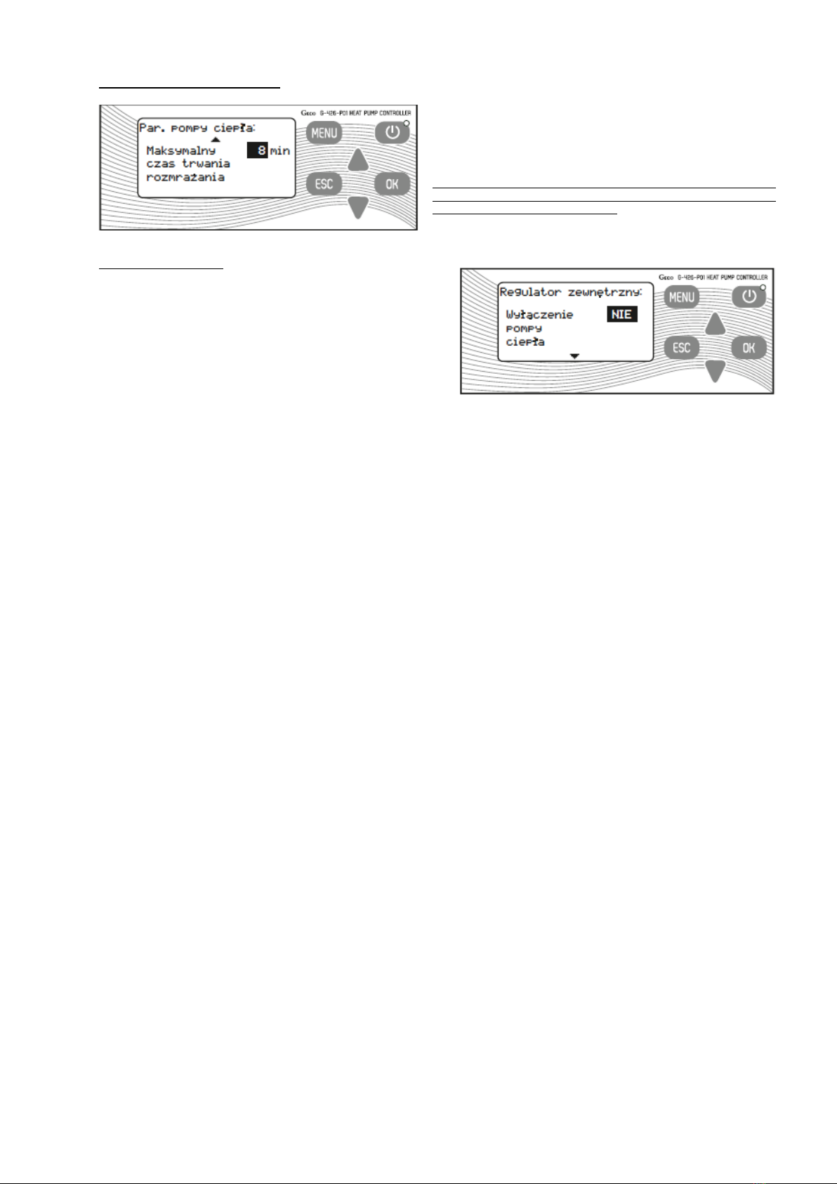
Maximum defrosting duration
Defrosting duration is the second parameter. Should it be exceeded,
the pump will also return to normal operation (it is enough if one of
the two conditions is satisfied).
Modification of defrosting parameters by a person, who does not
know the problem of heat pumps operation very well, may result in
deteriorated unit operation efficiency!
External control unit
Depending on the selected diagram, we are able to define, which
appliances are to be operated by the external control unit. For
example, if we set heat pump deactivation to NO, even after bridge
opening the heat pump will be working in compliance with the factory
controller.
Manual control
Otherwise called the relays test. Depending on the selected diagram, we are able to activate successively all devices
operated by the controller in order to check their correct operation. After exit to the main menu all devices return to their
standard settings.

8
Alarms review
Alarm
no.
Alarm designation
Possible cause
Solution
Consequences
Alarm 01
Defect of T1 temperature sensor
1) Incorrect sensor connection (no contact
with board socket, e.g. inserted into
connection block with insulation)
2) Broken or worn out sensor wire
3) No contact between connection block
and electric board
4) Damaged electric board
1) Check sensor seating in an electric
board
2) Check sensor resistance (5kQ)
3) Check connection block inserted into the
electric board
4) Check the electric board
1) No indications of ambient temp. - T1
2) No ‘Low COP’ function
3) Faster compressor wear at ambient
temperatures below -5°C
Alarm 02
Defect of T2 temperature sensor
1) No indications of tank temp. - T2
2) No ‘Low Temp.’ function
3) Pump operation stoppage for T2 control
4) Operation stoppage - T2-controlled
equipment (depending on diagrams -
solid fuel fired and gas-fired boiler)
Alarm 03
Defect of T3 temperature sensor
1) No indications of tank temp. - T3
2) Pump operation stoppage for T3 control
3) Operation stoppage - T3-controlled
equipment (circulating pump depending
on diagrams - solid fuel fired and gas-
fired boiler)
Alarm 04
Defect of T4 temperature sensor
1) No indications of boiler temp. - T4
2) Operation stoppage - solid fuel fired
boiler pump (F)
Alarm 06
Defect of T6 temperature sensor
1) No indications of water inlet temp. - T6
2) No anti-freezing protection
Alarm 07
Defect of T7 temperature sensor
1) No indications of water outlet temp. - T7
2) Operation stoppage for heat pump - T7
control
Alarm 08
Defect of T8 temperature sensor
1) No indications of ambient temp. - T8
2) Heat pump operation stoppage due to
the lack of evaporator defrosting
function and impossible expansion
valve operation
Alarm 09
Defect of T9 temperature sensor
1) No indications of temp. before
compressor - T9
2) Heat pump operation stoppage due to
expansion valve inactivity
Alarm 10
Defect of T10 temperature
sensor
1) Check sensor seating in an electric
board
2) Check sensor resistance (50kfi)
3) Check connection block inserted into the
electric board
4) Check the electric board
1) No indications of ambient temp. - T10
2) Missing ‘Over Temp.’ function (in critical
moments the pump will be switching off
through a fuse in wiring system or high/
low pressure error)
Alarm 17
Low pressure in the heat pump
working system
(Low Pres)
1) R410a medium leak from the system
2) Thick ice layer in evaporator (T8 sensor
defect)
3) Soiled filter or evaporator (choked air
flow)
4) Incorrect operation of low-pressure
control
5) Damaged expansion valve
6) Damaged T8 or T9 sensor
1) Connect an external manometer to
service stub pipe (pressure control
opening pressure 0.15MPa, closing
back pressure 0.30 MPa)
2) Clean evaporator and air filter
3) Report failure to HEWALEX service
4) Check pressure control operation
Heat pump operation stoppage until return to
normal pressure state. After occurrence of
boundary volume, within preset time heat
pump will enter alarm no. 19 status (Heat
pump stoppage). Required contact with
service.
Alarm 18
High pressure in the heat pump
working system
(High Pres)
1) Excess of R410a medium in the system
2) Too high water temp. in the tank
(incorrect temp. indications - T2 or T3),
3) T2 or T3 sensors not inserted in the tank)
4) Incorrect operation of high-pressure
control
5) Damaged expansion valve
1) Read pressure value from manometer
2) Check indications of water temp. in the
tank with an external temperature
sensor, and compare them with values
displayed in the controller
3) Check resistance and correct position of
the T2 and T3 sensors
4) Report failure to HEWALEX service
Heat pump operation stoppage until return to
normal pressure state. After occurrence of
boundary volume, within preset time heat
pump will enter alarm no. 19 status (Heat
pump stoppage). Required contact with
service.
Alarm 19
Heat pump stoppage. Required
contact with service.
1) Alarm no. 17 persisted more than 30 min.
or occurred 3 times within 30 min.
2) Alarm no. 18 persisted more than 30 min.
or occurred 3 times within 30 min.
The alarm is reset through instantaneous unit
cutting off from power supply. Contact with
service required.
Heat pump operation stoppage until reset.
Alarm 21
Exceeded permissible
temperature after compressor.
(Over Temp)
1) Motor of the compressor heats up, but it
does not pump the medium
2) Damaged condenser of the compressor
3) Bad resistance of T10 sensor
4) Too small volume of the R410a medium
5) Incorrect work of low- and high-pressure
control
6) Damaged expansion valve
1) Check compressor supply current
intensity
2) Check resistance of T10 sensor
3) Report failure to HEWALEX service
Heat pump operation stoppage until
temperature drop.

9
Controller messages review
Message
Definition
ExtOFF
External bridge open
HPOFF
Heat pump switched off (manually or by time program)
LowPres
Alarm no. 17
HighPres
Alarm no. 18
Defrost
Evaporator defrosting
STOP 180 (..., STOP 1)
Countdown until compressor restart
LowCOP
The T1 temp. lower than min. start-up temp. for heat pump
LowTemp
Too low temperature in the tank - the tank protection
AntiFreez
Protection against freezing for water cycle in heat pump
PreHeat
Preheating of oils in compressor with compressor heater
OverTemp
Alarm no. 21
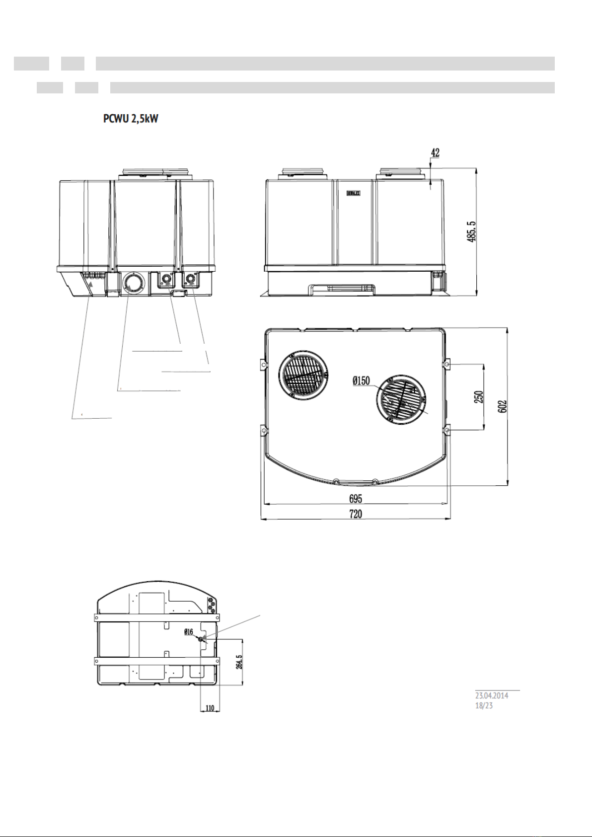
TECHNICAL DATA
Dimensions
condensate
discharge
View from bottom: position of condensate discharge stub pipe.
Water OUTLET from heat pump
Water INLET to heat pump
R410a medium pressure gauge after compressor
Electric chokes
cat. no.: HEWALEX: 91.10.13

Technical parameters list
Model
PCWU
2.5kW
Heating power (A7/W30-35)
kW
2.51
To the system with the tank
L
>80
Heat pump supply power (A7/W30-35)
kW
0.67
COP efficiency coefficient (A7/W30-35)
3.8
COP efficiency coefficient (A15/W15-45)
4.35
Supply voltage/frequency
V~/Hz
1~230/50
Number of compressors
1
Compressor type
rotary
Max. temp. of water heating with heat pump
°C
60
Air flow
m3/h
350/500
Air pumping pressure
Pa
40
Diameter of air stub pipes
mm
0150
Noise (measured at source)
dB(A)
45
Water terminals
inch
3/4
Condensate terminal
mm
16
Main source stream (AT=5°C)
l/min
11
Min. internal diameter of pipeline to the tank
mm
20
Max. length of pipeline to the tank
m
15
Working medium (weight)
-/(g)
R410a(1200)
Low-pressure control (OFF/ON)
MPa
0.02/0.15
High-pressure control (OFF/ON)
MPa
4.4/3.2
Max. required installation safety valve
MPa
0.7
Unit dimensions (L / W / H)
mm
720/600/490
Net weight
kg
45
Weight with packaging
kg
55
Heated water:
COP efficiency diagram
Inlet air temperature
(dry-bulb and wet-bulb thermometer
measurement)
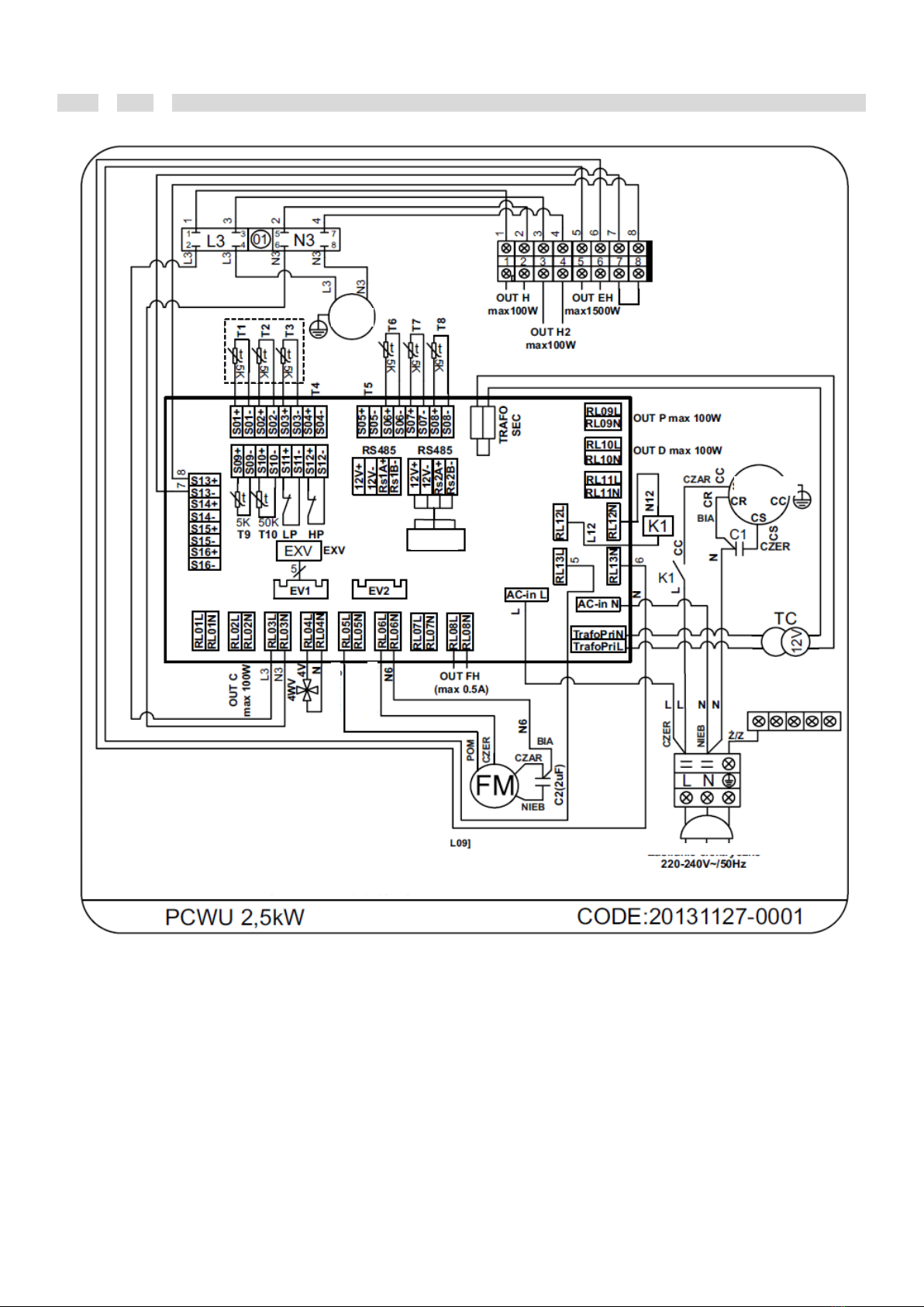
Wiring diagram
IN External
control unit
PUMP
Compressor
Controller
Power supply
T1: Ambient temperature [S01]
T2: Temp. at tank bottom [S02]
T3: Temp. at tank top [S03]
T4: Solid fuel fired boiler temp.[S04]
T5: Void [S05]
T6: Temp. of water inlet to PC[S06]
T7: Temp. of water outlet from PC[S07]
T8: Evaporator temp. [S08]
T9: Temp. before compressor [S09]
T10: Temp. after compressor [S10]
LP: Low-pressure control [S11]
HP: High-pressure control [S12]
IN External control unit
OUT C: Circulating pump [RL02]
OUT H: Circulating pump [RL03]
4WV: 4-way valve [RL04]
FM: fan speed - 1 [RL05]
FM: fan speed - 2 [RL06]
OUT FH: Electric heater [RL08]
OUT P: Pump for solid fuel fired boiler [RL09]
OUT D: Automatic boiler [RL10]
COMP: Compressor [RL12]
OUT EH: Electric heater [RL13]
EXV: Expansion valve [EV1]
High speed
Low speed
Other manuals for PCWU 2.5kW
1
Table of contents
Other Hewalex Heat Pump manuals

Popular Heat Pump manuals by other brands

Jula
Jula Anslut 417-030 operating instructions

Raypak
Raypak 5300 owner's manual

Tekno Point
Tekno Point ATHENA C200 User and installation manual

Daikin
Daikin RCS Series Installation and Maintenance

iDM
iDM AERO SLM 3-11 Technical documentation installation instructions

GE
GE AZ58H12EADM1 and Owner's manual and installation instructions


