Hewland NMT User guide

PAGE 1
© Copyright Hewland Engineering Limited
SERVICING INSTRUCTIONS AND ILLUSTRATED
PARTS LIST FOR HEWLAND NMT GEARBOXES
HEWLAND ENGINEERING LTD
WALTHAM ROAD, WHITE WALTHAM,
Last Update 10th July 2012
MAIDENHEAD, BERKSHIRE,
SL6 3LR, ENGLAND

PAGE 2
© Copyright Hewland Engineering Limited
CONTENTS :-
page page
Technical specification 4 Changing gear ratios 13
General notes 5 Powerflow differential 14
Differential bearing preload 6 Differential Options 15
Pinion shaft mounting 7 Illustrated Parts List 22
Pinion shaft bearing preload 8 Gearbox Tooling 35
Crownwheel backlash setting 9 General Technical Bulletins 36
Sequential barrel setting 10 Oil system layout 38
Gearbox assembly 11 Recommended Tightening 39
Torques

PAGE 3
© Copyright Hewland Engineering Limited
ILLUSTRATIONS :-
page page
fig.1 Differential bearing preload 6 fig.12 Casings & Associated Parts 25
fig.2 Pinion shaft setting 7 fig.13 Layshaft Assembly 27
fig.3 Pinion shaft bearing preload 8 fig.14 Pinion Shaft Assembly 29
fig.4 Crownwheel setting 9 fig.15 Selector Assembly 31
fig.5 Sequential barrel setting 10 fig.16 NLT-218-Tripod Assembly 33
fig.6 Powerflow diff assembly 14 fig.17 Gearbox Tooling 35
fig.7-10 Differential Assemblies 15-21 fig.18 Oil system layout 38
fig.11 Differential Subsidiary Parts 23

PAGE 4
© Copyright Hewland Engineering Limited
TECHNICAL SPECIFICATION
The NMT gearbox is a transaxle unit, designed for mid-engined, rear wheel drive cars. The unit is produced with six
forward gears, reverse, and a powerflow differential.
The gear selection mechanism is sequential, with a separate, mechanically interlocked reverse engagement mechanism.
The drive is taken from the engine via the clutch shaft, which turns input and pinion gears to drive the final transmission
assembly.
Gear changing is effected through non-synchronising face dogs. An extensive range of gear ratios provides a wide
range of gearing requirements. The gear ratios and differential assembly can easily be changed without removing the
gearbox from the vehicle.
Heat treated nickel chrome steel is used to manufacture all gears and shafts. The selector forks are also steel.
Lubrication is by splash or optional internal pump with distribution circuit, and the oil is retained by lipped oil seals.
In general configuration, the NMT-200 is a high tech racing transaxle unit which achieves the maximum effective use of
power, in conjunction with extremely stiff integral rear suspension mountings.
weight (AL) 128 lbs (58 Kg) 1st to 6th gear ratios from 3.31:1 to .89:1
oil type SAE 80 or 90 final drive ratio 11/31, 10/31, 9/31
oil quantity 7 pints (4 litres) clutch shaft made to customer's requirements
max. torque 320 lbs.ft (430 Nm) Pinion shaft nut tightening torque = 120 lbs.ft (163 Nm)
Crownwheelbolts=75lbs.ft(100Nm)

PAGE 5
© Copyright Hewland Engineering Limited
GENERAL NOTES :-
a/ Read these instructions carefully and with reference to the illustrations.
b/ Before dismantling the gearbox, see that a clean tray is available, in which to place the parts.
c/ Thoroughly clean and inspect all parts before reassembly. Discard any worn or damaged components and replace with new
ones.
d/ Use only genuine Hewland parts as replacements. These are manufactured in our workshops to the fine tolerances necessary and
are rigorously inspected.
e/ Always ensure that locknuts, and oil seals are in good condition when reassembling.
f/ All studs and screws must be Loctited or wirelocked in position, unless stated otherwise
g/ Bearing Replacement :-
Bearings can only be removed or renewed if the casings have been warmed in an oven, or with a blowlamp. In the latter case,
keep the blowlamp moving while heating the casing.
Note: Do not overheat. Test with a spot of water which will bounce off at the correct temperature.
Once a casing is heated, all bearings should be pressed into their respective seatings without delay, thus eliminating the need to
reheat. At the correct temperature, fitting the bearings should present no difficulty.
During cooling, or when the casings have cooled, it is advisable to once more lightly press the bearings to ensure that they are
correctly seated.
h/ Oil:
Fill the gearbox through the plug hole on top of the maincase. The oil will find it's own level within the gearbox.
Note: Too much oil will not directly cause any harm, but is undesirable as it may induce power loss and overheating of internals.
PAGE 6
© Copyright Hewland Engineering Limited
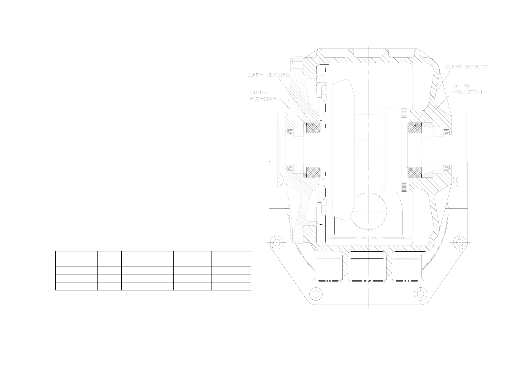
DIFFERENTIAL BEARING PRELOAD
Requires special tool No. SK-119-FGC
Assemble the differential case (57) and end cap (58),
and bolt the crownwheel (56) to it. Fit the differential
unit into the maincase (1) using dummy bearings SK-
119-FGC, and fit the sideplate (3). Adjust the shims
(103) if necessary, to achieve 4 – 6 lbs.ft of bearing
preload torque (to turn the diff assembly in it’s bearings
when oiled.).
The table below is to inform you of which sideplate
spacers should be used with which crownwheel when
mounted on a TPT differential. The reason that there are
two sets of spacers, is that the crownwheels have
different mounting distances.
FIGURE 1
PART No. RATIO MOUNTING
DIST
ITEM (90) ITEM (91)
NMT-221-AW 11/31 2.316” FGC-206-2A NMT-205-2
NMT-221-BW 10/31 2.316” FGC-206-2A NMT-205-2
NLT-221-CW 9/35 2.200” FGC-205-2A NMT-205-2A
PAGE 7
© Copyright Hewland Engineering Limited
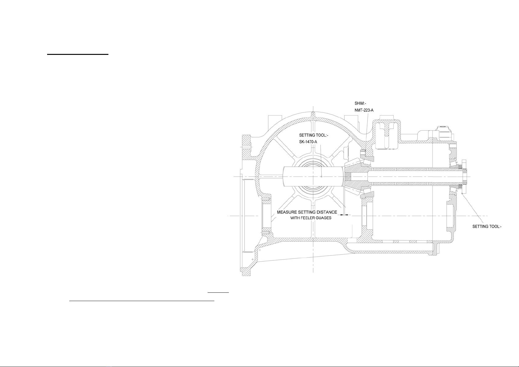
FIGURE 2
PINION SETTING
Requires special tool No.SK-1470-A & SK-1913
Press the pinion head bearing inner (37) onto the
pinion shaft (4). Fit the bearing housing (37) and
shims (40) into the maincase. Assemble the pinion
shaft into the maincase (1) and fit the bearing carrier
(2). Tighten the pinion shaft nut (111) onto the
pinion shaft until the pinion shaft requires 20-25
lbs.ins to turn it in it's bearings (equivalent to a
tangential force of 16-20 lbs at the outside diameter
of tool SK-1913)
Fit tool SK-1470-A into the maincase diff bearing
bore, and use feeler gauges to measure the gap
between the tool and the pinion front face. This
clearance should comply with the dimension
indicated on the pinion shaft label (also stamped on
the front face of the pinion shaft), and can be
adjusted by adding or removing shims (40) from
behind the pinion head bearing housing (37).
Alternatively, the pinion mounting distance can be
measured with a height gauge, and set to the
dimension on the pinion shaft label.
Note: It is not correct practice to replace a pinion
shaft without measuring the setting distance, even if
the old and new shafts have the same calibration.
SK-1913
PAGE 8
© Copyright Hewland Engineering Limited
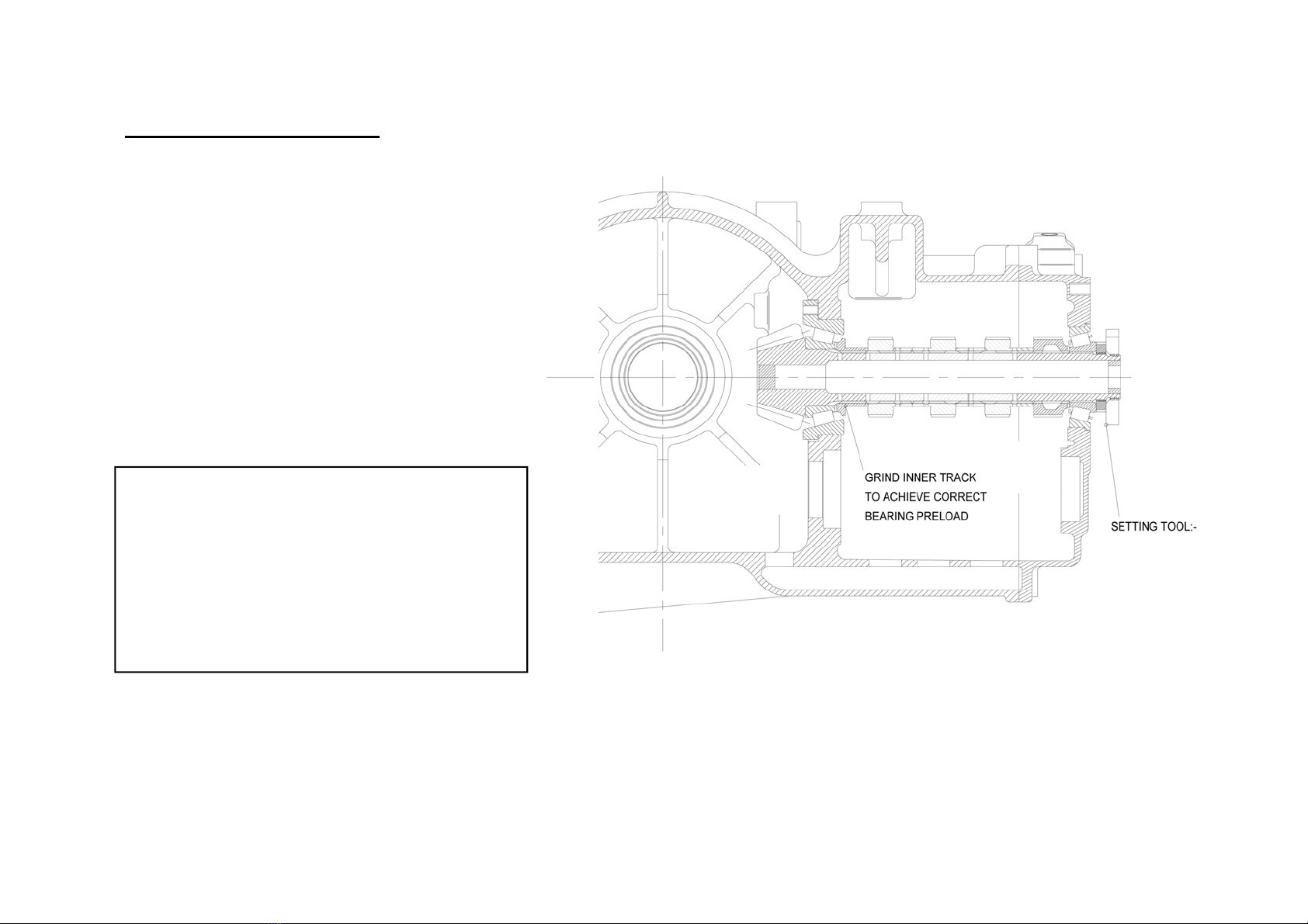
PINION BEARING PRELOAD
Requires special tool No.SK-1913
Having installed the correct pinion shaft
bearing shims, remove the bearing carrier
(2). Add the spacer (14) and hubs (20,33) to
the pinion shaft, and replace the bearing
carrier. The thickness of the spacer (14)
should be adjusted, by grinding, to give a
bearing preload torque of 20-25 lbs.ins with
oiled bearings (measure torque as when
setting pinion shaft, using tool SK-1913).
FIGURE 3
It is essential that the pinion bearing preload
is checked and adjusted if any of the pinion
shaft components are replaced, with the ex-
ception of the locknut and locking ring.
Fitting a longer six gear spacer (14) will de-
crease the pinion bearing
preload, whereas shortening the six gear
spacer (14) will increase the pinion bearing
preload.
SK-1913

PAGE 9
© Copyright Hewland Engineering Limited
CROWNWHEEL & PINION BACKLASH SETTING
Requires special tool No. SK-1913
With the pinion shaft correctly fitted, and the correct diff
bearing shims ascertained, the actual backlash can be
measured by means of a dial test indicator against the
notch in the outside diameter of tool SK-1913. Be sure to
take at least 6 backlash readings, turning the crownwheel
30-45 degrees between each reading (this is to ensure
that any variation due to manufacturing tolerances are
taken account of.
The correct backlash figure should be taken from the
card supplied with the gears. If the measured backlash is
incorrect, rectify it by removing some shims (103) from
behind one diff bearing, and inserting them behind the
other, thus moving the diff across in the maincase. Do
not add or discard any shims at this stage, as to do so
would affect the diff bearing preload.
Once the correct backlash has been achieved, replace the
dummy bearings with bearings (83) and confirm that the
backlash is correct.
Note: Dummy are used so that it is easy to change the shims
during the setting procedures. Before fitting the actual diff
bearings, it is important compare thier width with that of the
dummy bearings and compensate the shims accordingly for any
difference.
FIGURE 4
PAGE 10
© Copyright Hewland Engineering Limited
FIGURE 5
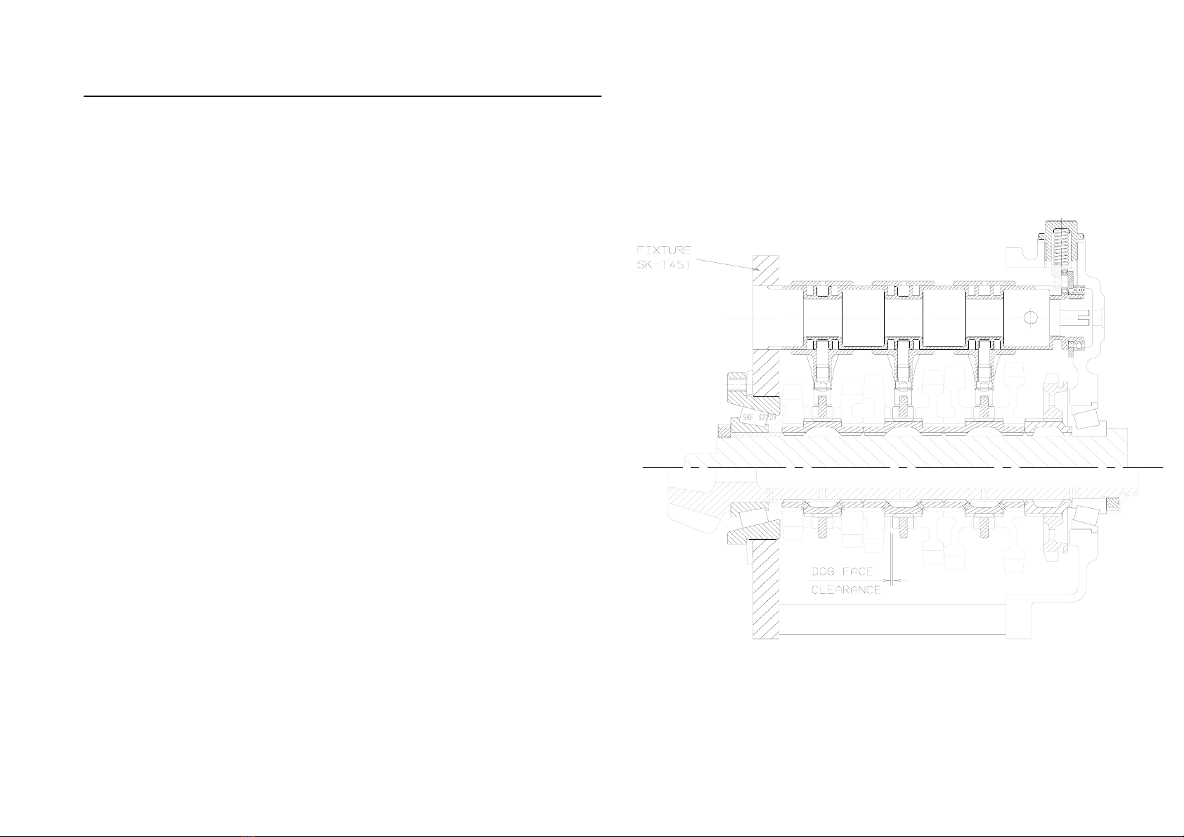
SEQUENTIAL BARREL SETTING - Requires special tool No.SK-1451
a/ Assemble the barrel (15), spacer (26), bearing retaining plate (25),
bearing (27), and nut (29). Heat the bearing carrier (2), slide the barrel
assembly into the bearing carrier, and secure using screws (12).
b/ Place the roller (24) onto the detent plunger (21), and insert them into
the bearing carrier (2). Add the detent spring (22), bonded seal (115),
and detent plug (23).
c/ Slide the selector forks (17) over the barrel (15), and secure using
selector pins (18). For final assembly, Loctite the pins (18) into the forks
(17).
d/ Stack the pinion gears (16), hubs (19,20), clutch rings (19) and spacer
(14) in place in the bearing carrier, and slide the whole thing onto the
dummy shaft of fixture SK-1451.
e/ Tighten the pinion shaft nut (111) onto the end of the dummy shaft,
ensuring that the disc spring on the fixture preloads the bearings.
f/ Rotate the barrel to engage first gear. Measure and record the gap
between the dogfaces of third through sixth gears. Engage third gear and
repeat the measurement for first and second dogfaces. It is important
that these dimensions are not taken when the barrel is in the neutral
position.
First, third and fifth gear dog gap measurements will be similar (as will
second, fourth and sixth). Any difference between the odd & even gear
measurements must be corrected by replacing the barrel spacer (26) with
one of the correct thickness.
Note: It is not possible (or necessary) to individually adjust each fork.

PAGE 11
© Copyright Hewland Engineering Limited
GEARBOX - ASSEMBLY
a/ It is assumed that all bearings, oil seals, studs, oil jets, and dowels are already fitted into casing. (see page 5).
b/ Assemble the oil pump components (if required). Heat the maincase, and drop the pump into position. Secure with screws , and add the drive
gear and circlip.
c/ Place the reverse idler gear (104), bearing (106), and thrust washers (107) in position in the bearing carrier, and slide the spigot (105) into
position. Secure with screw (12).
d/ Assemble the selector rack (75), washers (76), spring (77), and circlip (78), and slide into the maincase. Secure with the selector rack stop
(80). Note: Check the gear linkage return spring length regularly (item 77). This spring has a finite life and will weaken with use. A new
spring has a free height of 1.450”. It is also adviseable never to re-use the circlip (78).
e/ Assemble the drum (8), bearing (28), pin (10), retaining plate (11), barrel driver (13), and shifter spindle (7). Assemble the drum shifter (6),
guide plate (9), pawls (64), springs (63), and plungers (62), and slide into engagement with the drum assembly. Push the complete assembly
into it's location in the maincase, ensuring correct location with the selector rack teeth.
f/ Assemble the selector input shaft (70), bearing (68), seal (71), spacer (72), quadrant gear (73) and circlip (112) into their housing (66). Slide
the whole assembly into the maincase, ensuring correct engagement with the selector rack (75).
g/ Build the selector barrel parts into the bearing carrier as described in the section 'Sequential Barrel Setting'.
h/ Fit the pinion shaft as described previously.
i/ Hold the reverse selector fork (31), with reverse pinion gear (121), in position in the bearing carrier (2). Slide the reverse selector shaft (110)
into place and secure with screw (122).

PAGE 12
© Copyright Hewland Engineering Limited
j/ With the bearing carrier face up, add the layshaft (50), input gears (46), spacers (45), disc spring (44), and bearing inner track
(43). Stack the reverse hub (33), hubs (20), pinion gears (16), bearings (120), clutch rings (19), and spacer (14) into position in
the bearing carrier (2), and slide the dummy shaft through from the bearing carrier end.
k/ Locating the tip of the dummy shaft into the end of the pinion shaft, slide the completed gear cluster assembly into the maincase
to engage the pinion shaft and layshaft bearing, allowing the dummy shaft to slide out of the gear cluster. Whilst locating the
gear cluster, lightly operate the selector rack (75) to ensure correct location of the barrel and driver.
Tighten the pinion shaft nut using tool No. SK-1452
l/ Fit the rear cover (36) using nuts (49). and dowels (139).
m/ Fit the clutch spigot bearing (97) and seal (98) into their housing (99) and secure with circlip (101). Slide the housing assembly
onto the clutch shaft (96) and secure with circlip (102). Fit the o'ring seal (100) onto the housing and slide the assembly into the
maincase to engage the layshaft (50). Fix the housing in place using screws (124).
Note : If the oil pump is fitted, the diff assembly must be removed from the maincase to allow the clutch shaft to be fitted (or
removed).
n/ Fit magnetic plug (114) and washer (115) to maincase.

PAGE 13
© Copyright Hewland Engineering Limited
CHANGING GEAR RATIOS
a/ With a drip tray placed beneath the gearbox, remove the drain plug (114) and drain the oil.
b/ Disconnect the reverse gear linkage from the gearbox.
c/ Remove the rear cover (36).
c/ Remove the M8 nuts (48) securing the bearing carrier (2), and slide it out of the maincase, complete with the gear cluster. It may
be necessary to tap lightly on the lugs provided to break the seal. Use a soft hammer for this purpose, never use a screwdriver to
lever between joint faces as this may damage the faces and impair the seal efficiency when reassembled. Take care not to drop
any of the pinion shaft components as they won't be fully supported at this time. The dummy shaft from SK-1451 can be used to
prevent the pinion shaft components from falling by inserting it into the rear end of the pinion shaft and sliding the loose parts
onto it.
d/ Remove the pinion gears (16), hubs (20), and clutch rings (19). Slide the input gears (46), and spacers (45) from the layshaft
(50), then withdraw the layshaft from the bearing carrier.
e/ Replace the gears with the required ratios. Gears are supplied in matched pairs, one for the mainshaft and one for the layshaft.
Each gear is marked with two sets of numbers. The first of these indicates the number of teeth on the layshaft gear, while the
second figure signifies the number of teeth on the mainshaft gear which mates with it. Both gears of each pair are marked in an
identical manner. It is essential that gears are correctly paired to these numbers.
Note: On all first gears, and some second gears, the gear teeth are machined integral with the layshaft. In such cases, therefore, if
a first (or second) gear ratio change is required, the layshaft itself must be changed.
f/ Whilst changing ratios it is advisable, as a matter of course, to wash and inspect all components which are to be used again
before refitting. Check for wear and cracks, particularly to the clutch rings. Also examine the selector forks for heavy or uneven
wear.
g/ Reassembly is the reverse of disassembly. Take care, when refitting the gear cluster into the maincase, to ensure location of the
layshaft into it's bearing, and of the selector barrel (15) it's driver (13). Assembly of the pinion shaft components is made easier
by use of the dummy shaft as described previously. [Some mechanics find assembly easier if the layshaft bearing inner track is
pre-fitted in the casing, rather than onto the end of the layshaft.]
PAGE 14
© Copyright Hewland Engineering Limited
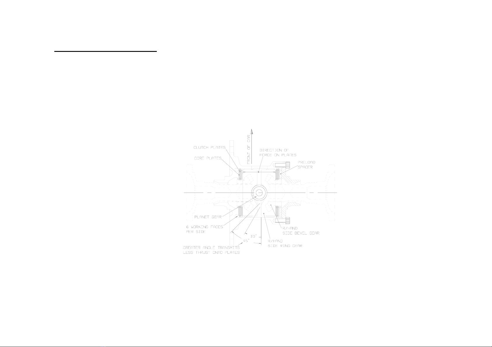
POWERFLOW DIFFERENTIAL
This powerflow differential unit is designed with versatility as it's major asset. Many factors will contribute to the settings required. A car with
good traction and low power, may require a completely different arrangement to that of a car with poor traction and high power.
There are 10 friction plates within the unit (4 (87) splined to the diff casing (57), and 6 (88) splined to the side bevel gears(84). Slip limiting is
dependant on the friction resistance between these plates, and is affected by clamping the plates together.. Four factors contribute to the total
friction torque between the plates :-
3/ The second adjustable factor is
how tightly the plate stack is
compressed on assembly (known
as static preload). Included in the
plate stack is a preload spacer
(89). The preload torque is
measured between the side bevel
gears, by holding one side bevel
gear (84) stationary, and
measuring the torque required to
turn the other using tool SK-____.
When the diff is assembled, the
preload torque must be at least 10
lbs.ft, but can be much greater if
required. New plates ‘run in’ so a
higher preload is advised than
with used plates.
4/ The final adjustment is simply to
re-order the plate stack so as to
change the number of relatively
rotating faces. The diagram shows
the stack setup with the maximum
12 working faces. Standard stack
may be shuffled to give as few as
2 working faces.
1/ The side bevel gears (84) thrust
apart to clamp the plates as they
transmit the driving power. This
is a feature of the gear geometry,
and is not adjustable.
2/ The ramp angles cut on the side
ring gears (85) have an effect on
how much of the transmitted
torque is converted into sideways
(clamping) force onto the plates.
For example, on the drive side
ramp, 45 degrees transmits less
sideways force than 30 degrees.
Likewise on the coast side ramp,
an 80 degree angle will transmit
little or no clamping force onto
the plates, whereas a 45 degree
angle will transmit a much
greater force. Side ring gears
(85) are available with many
different drive/coast ramp angle
combinations.
FIG URE 6
PAGE 15
© Copyright Hewland Engineering Limited
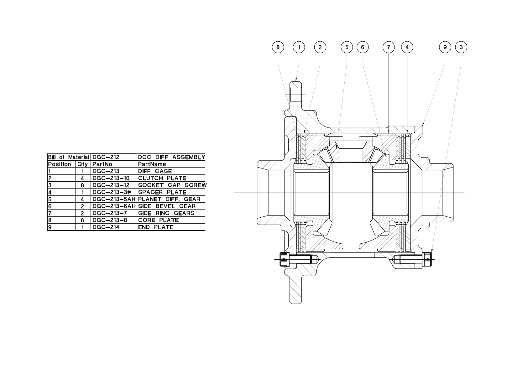
FIGURE 7
DGC-212 Diff Assembly (superseded March 2010)
PAGE 16
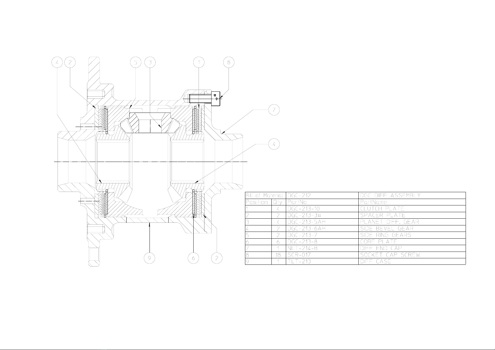
© Copyright Hewland Engineering Limited
DGC-212 Diff Assembly (March 2010 onwards)
FIGURE 7a
PAGE 17
© Copyright Hewland Engineering Limited
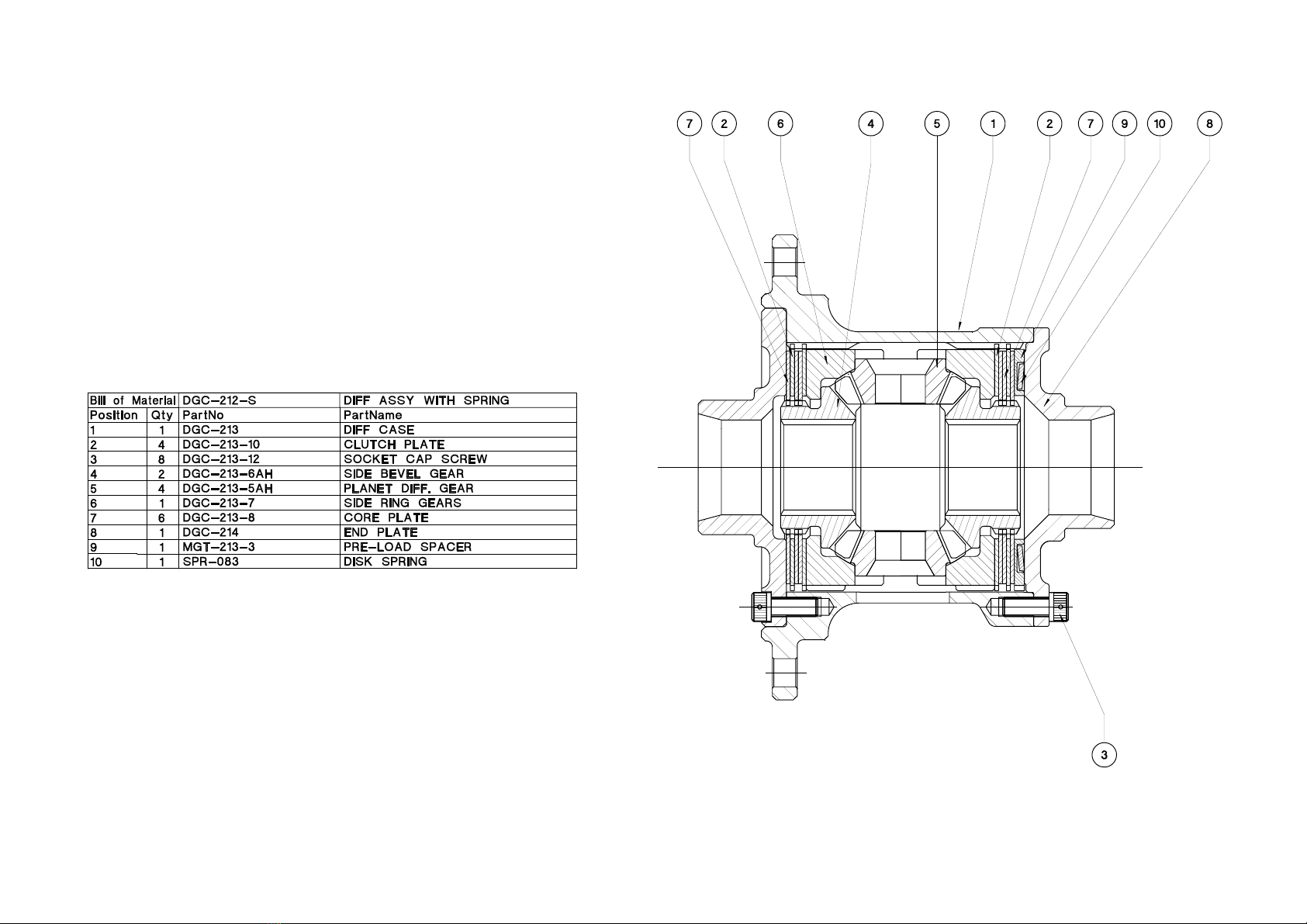
FIGURE 8
DGC-212-S Diff Assembly (superseded March 2010)

PAGE 18
© Copyright Hewland Engineering Limited
DGC-212-S Diff Assembly (March 2010 onwards)
FIGURE 8a

PAGE 19
© Copyright Hewland Engineering Limited
TPT-212 Diff Assembly
FIGURE 9

PAGE 20
© Copyright Hewland Engineering Limited
IN ORDER TO FIT THE NLT DIFFERNETIAL
IN THE NMT BOX, THE NLT SIDE PLATE
(NLT-205) WILL NEED TO BE FITTED
FIGURE 10
NLT-212 Diff Assembly (superseded March 2009)
This differential was superseded
by the differential shown on the
next page.
Table of contents


