Hewlett Packard Enterprise Storage Operating and safety instructions

HPE Moonshot 1500 Chassis 2.0 Setup and
Installation Guide
Part Number: P26788-001
Published: February 2020
Edition: 1
Abstract
This document contains setup, installation, and configuration information for the HPE Moonshot 1500
Chassis 20. This document is for the person who installs, administers, and troubleshoots the Moonshot
1500 Chassis 20. HPE assumes you are qualified in the servicing of computer equipment and trained in
recognizing hazards in products with hazardous energy levels.

©Copyright 2020 Hewlett Packard Enterprise Development LP
Notices
The information contained herein is subject to change without notice. The only warranties for Hewlett Packard Enterprise
products and services are set forth in the express warranty statements accompanying such products and services.
Nothing herein should be construed as constituting an additional warranty. Hewlett Packard Enterprise shall not be liable
for technical or editorial errors or omissions contained herein.
Confidential computer software. Valid license from Hewlett Packard Enterprise required for possession, use, or copying.
Consistent with FAR 12211 and 12212, Commercial Computer Software, Computer Software Documentation, and
Technical Data for Commercial Items are licensed to the U.S. Government under vendor's standard commercial license.
Links to third-party websites take you outside the Hewlett Packard Enterprise website. Hewlett Packard Enterprise has no
control over and is not responsible for information outside the Hewlett Packard Enterprise website.
Acknowledgments
Intel®, Itanium®, Optane™, Pentium®, Xeon®, Intel Inside®, and the Intel Inside logo are trademarks of Intel Corporation
in the U.S. and other countries.
Microsoft®and Windows®are either registered trademarks or trademarks of Microsoft Corporation in the United States
and/or other countries.
Adobe®and Acrobat®are trademarks of Adobe Systems Incorporated.
Java®and Oracle®are registered trademarks of Oracle and/or its ailiates.
UNIX®is a registered trademark of The Open Group.
All third-party marks are property of their respective owners.

Contents
Planning an installation....................................................................................................6
Safety and regulatory compliance......................................................................................................................................................................... 6
Site requirements.............................................................................................................................................................................................................6
Software prerequisites..................................................................................................................................................................................................6
Determine power and cooling configurations.................................................................................................................................................6
Power requirements.......................................................................................................................................................................................................6
Hot-plug power supply calculations.....................................................................................................................................................................7
Compiling the documentation..................................................................................................................................................................................7
Warnings and cautions................................................................................................................................................................................................. 7
Space and airflow requirements..............................................................................................................................................................................8
Temperature requirements........................................................................................................................................................................................9
Grounding requirements............................................................................................................................................................................................. 9
Identifying components and LEDs............................................................................... 10
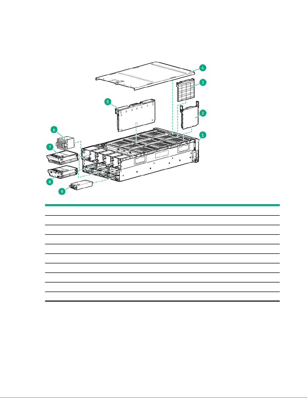
HPE Moonshot 1500 Chassis 20 components.......................................................................................................................................... 10
Chassis front panel components..........................................................................................................................................................................11
Chassis front panel LEDs and buttons.............................................................................................................................................................11
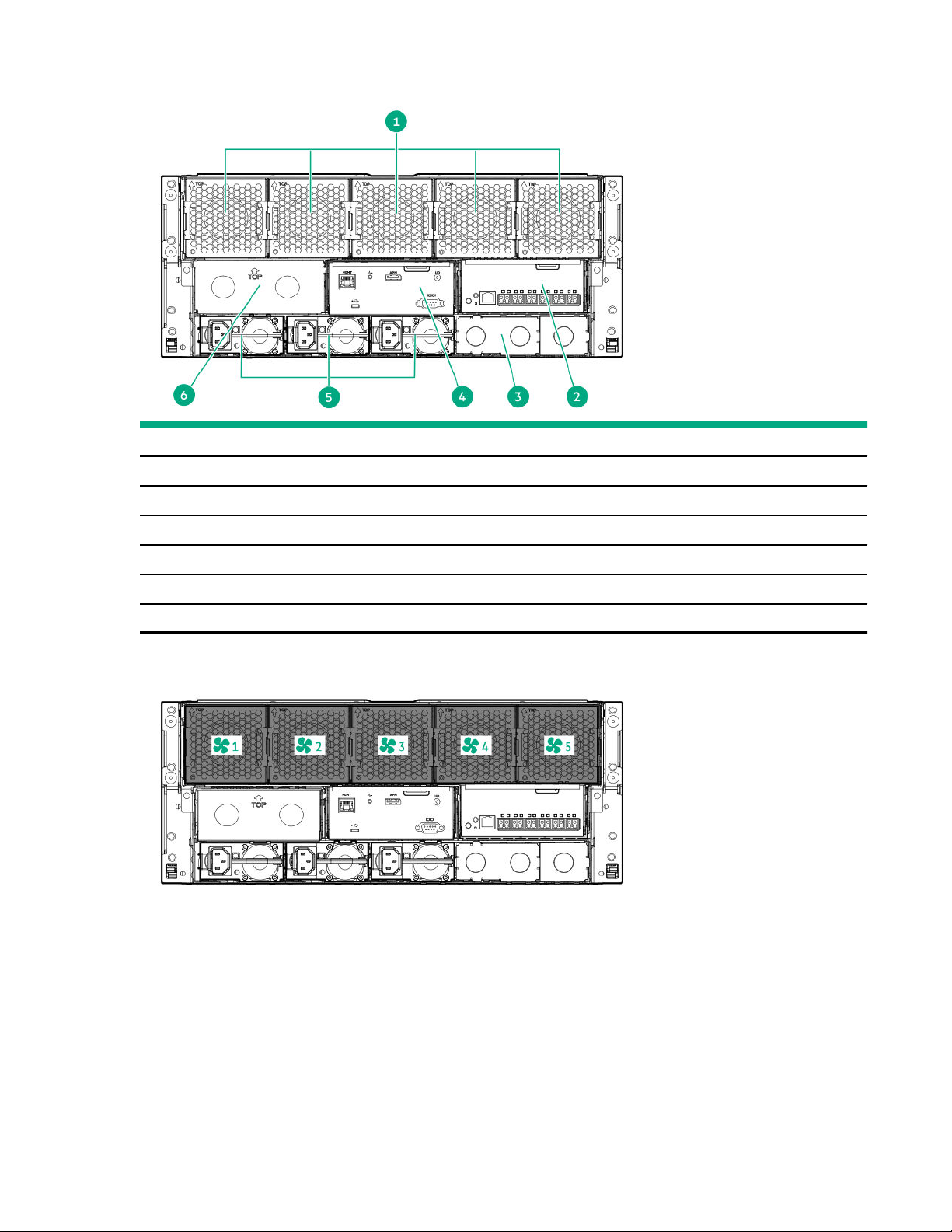
Chassis rear panel components............................................................................................................................................................................13
Fan bay numbering.................................................................................................................................................................................... 13
Fan LED.............................................................................................................................................................................................................14
Power supply bay numbering.............................................................................................................................................................. 14
Power supply LED.......................................................................................................................................................................................14
Uplink module bay identification....................................................................................................................................................... 15
Moonshot-4QSFP+ Uplink Module components...................................................................................................................... 15
Moonshot-4QSFP+ Uplink Module LEDs and buttons..........................................................................................................16
Moonshot-16SFP+ Uplink Module components.......................................................................................................................17
Moonshot-16SFP+ Uplink Module LEDs and buttons.......................................................................................................... 17
HPE Moonshot 1500 Chassis Management Module 20 components........................................................................18
HPE Moonshot 1500 Chassis Management Module 20 LEDs and buttons........................................................... 19
Chassis internal components................................................................................................................................................................................. 19
Server blade slot and switch module bay identification.......................................................................................................19
Server blade LEDs and buttons..........................................................................................................................................................20
Switch module button, sensor, and LEDs......................................................................................................................................21
Chassis population rules................................................................................................ 23
HPE Moonshot 1500 Chassis 20 population rules..................................................................................................................................23
Installing the chassis.......................................................................................................24
Installation overview...................................................................................................................................................................................................24
Unpacking the Moonshot 1500 Chassis 20.................................................................................................................................................24
Determining the chassis rack spacing.............................................................................................................................................................. 24
Installing the rack rails...............................................................................................................................................................................................24
Installing the chassis in the rack.......................................................................................................................................................................... 24
Installing the blanking panel.................................................................................................................................................................................. 28
Installing the Moonshot 1500 Chassis 20 components....................................................................................................................... 29
3

Installing the HPE Moonshot Chassis 20 ................................................................................................................................... 30
Installing a power supply........................................................................................................................................................................30
Installing the fans........................................................................................................................................................................................30
Installing the server blade......................................................................................................................................................................31
Drivers, firmware, and software updates.......................................................................................................................................32
Supported browsers.................................................................................................................................................................................. 32
Installing network components...........................................................................................................................................................32
Cabling the HPE Moonshot 1500 Chassis 2.0 ............................................................39
Cabling overview...........................................................................................................................................................................................................39
Connecting the HPE Moonshot 1500 Chassis Manager 20 to a network................................................................................. 39
Data center management network................................................................................................................................................... 39
Data center production network........................................................................................................................................................ 40
Connecting power cables and applying power to the chassis............................................................................................................41
Power-on events..........................................................................................................................................................................................41
Connecting to the HPE Moonshot Chassis Manager 20 serial interface....................................................................................41
Routing cables on the cable management arm...........................................................................................................................................41
Configuring the HPE Moonshot 1500 Chassis 2.0.....................................................42
Chassis configuration overview............................................................................................................................................................................42
Configure the chassis................................................................................................................................................................................42
Configure the switch..................................................................................................................................................................................47
Power capping................................................................................................................................................................................................................49
Power capping.............................................................................................................................................................................................. 49
Configuring a power cap.........................................................................................................................................................................51
Troubleshooting ............................................................................................................. 52
Troubleshooting resources..................................................................................................................................................................................... 52
Regulatory information .................................................................................................53
Safety and regulatory compliance...................................................................................................................................................................... 53
Belarus Kazakhstan Russia marking..................................................................................................................................................................53
Turkey RoHS material content declaration...................................................................................................................................................54
Ukraine RoHS material content declaration..................................................................................................................................................54
Warranty information................................................................................................................................................................................................. 54
Electrostatic discharge ..................................................................................................55
Preventing electrostatic discharge.....................................................................................................................................................................55
Grounding methods to prevent electrostatic discharge........................................................................................................................55
Specifications .................................................................................................................. 56
Chassis environmental specifications............................................................................................................................................................... 56
Chassis specifications.................................................................................................................................................................................................56
Websites............................................................................................................................57
Support and other resources........................................................................................ 58
4

Accessing Hewlett Packard Enterprise Support.........................................................................................................................................58
Accessing updates....................................................................................................................................................................................................... 58
Remote support.............................................................................................................................................................................................................59
Warranty information................................................................................................................................................................................................. 59
Regulatory information............................................................................................................................................................................................. 59
Documentation feedback......................................................................................................................................................................................... 60
5

Planning an installation
Safety and regulatory compliance
For safety, environmental, and regulatory information, see Safety and Compliance Information for Server, Storage, Power,
Networking, and Rack Products, available at the HPE website (https://www.hpe.com/support/Safety-Compliance-
EnterpriseProducts).
Site requirements
Select an installation site that meets the detailed installation site requirements described in the HPE Moonshot System
site planning guide in the HPE Moonshot Information Library (https://www.hpe.com/info/moonshot-docs).
Software prerequisites
Before setting up and configuring the HPE Moonshot 1500 Chassis Manager 20 :
• Obtain an operating system supported by the server blades installed in the HPE Moonshot 1500 Chassis 20 (see
https://www.hpe.com/info/supportos for OS support information). Operating systems cannot be deployed directly
from the HPE Moonshot 1500 Chassis Manager 20 .
• Operating systems can be deployed to the server blades using each server blade's iLO, through Intelligent
Provisioning or PXE boot. For deployment procedures, see operating system deployment documentation in the HPE
Moonshot Information Library (https://www.hpe.com/info/moonshot-docs).
• Update the firmware and system software components using HPE Moonshot Component Pack.
HPE Moonshot Component Pack is a comprehensive firmware solution tested on the Moonshot 1500 Chassis 20 and
delivered as a compressed file. The compressed file includes all the component files needed to update a Moonshot 1500
Chassis 20. Download the latest pack from the HPE website.
For a complete list of HPE Moonshot 1500 Chassis 20 documentation, see the HPE Moonshot Information Library
(https://www.hpe.com/info/moonshot-docs).
Determine power and cooling configurations
Validate power and cooling requirements based on location and installed components. For more information, see the HPE
Moonshot 1500 Chassis 2.0 Configuration and Compatibility guide in the Information Library (https://www.hpe.com/
info/moonshot-docs).
Power requirements
Installation of this equipment must comply with local and regional electrical regulations governing the installation of IT
equipment by licensed electricians. This equipment is designed to operate in installations covered by NFPA 70, 1999
Edition (National Electric Code) and NFPA-75, 1992 (code for Protection of Electronic Computer/Data Processing
Equipment). For electrical power ratings on options, refer to the product rating label or the user documentation supplied
with that option.
6Planning an installation

WARNING: To reduce the risk of personal injury, fire, or damage to the equipment, do not overload the AC supply
branch circuit that provides power to the rack. Consult the electrical authority having jurisdiction over wiring and
installation requirements of your facility.
CAUTION: Protect the chassis from power fluctuations and temporary interruptions with a regulating UPS. This
device protects the hardware from damage caused by power surges and voltage spikes and keeps the chassis in
operation during a power failure.
Hot-plug power supply calculations
For hot-plug power supply specifications and calculators to determine electrical and heat loading for the HPE Moonshot
1500 Chassis 20, see the HPE Power Advisor on the HPE website (https://www.hpe.com/info/hpepoweradvisor).
Compiling the documentation
The documentation, while delivered individually and in various formats, works as a system. See these documents before
attempting installation. These documents provide required important safety information and decision-making steps for
configuration. For more Moonshot 1500 Chassis 20 information, see HPE Moonshot Information Library (https://
www.hpe.com/info/moonshot-docs):
•Quick deploy rail system installation instructions
•HPE Moonshot System site planning guide
•HPE Moonshot 1500 Chassis 2.0 Configuration and Compatibility Guide
•HPE Moonshot 1500 Chassis 2.0 Maintenance and Service Guide
•HPE Moonshot Chassis Manager 2.0 CLI User Guide
•HPE Moonshot Chassis Manager 2.0 User Guide
•HPE Moonshot 1500 Chassis 2.0 Networking Cookbook
•HPE Moonshot 1500 Chassis 2.0 Troubleshooting Guide
•HPE Moonshot Component Pack Update Guide for Moonshot 1500 Chassis 2.0
Warnings and cautions
WARNING: To reduce the risk of personal injury or damage to equipment, heed all warnings and cautions
throughout the installation instructions.
Planning an installation 7

WARNING: To reduce the risk of personal injury or damage to the equipment, be sure that:
• The rack is bolted to the floor using the concrete anchor kit.
• The leveling feet extend to the floor.
• The full weight of the rack rests on the leveling feet.
• The racks are coupled together in multiple rack installations.
• Only one component is extended at a time. If more than one component is extended, a rack might become
unstable.
WARNING: The chassis is very heavy. To reduce the risk of personal injury or damage to the equipment, do the
following:
• Observe local occupational health and safety requirements and guidelines for manual material handling.
• Get help to lift and stabilize the product during installation or removal, especially when the product is not
fastened to the rails. The chassis weighs more than 8165 kg (18000 lb), so at least four people must lift the
chassis into the rack together. An additional person may be required to help align the chassis if the chassis is
installed higher than chest level.
WARNING: To reduce the risk of personal injury or damage to the equipment, you must adequately support the
chassis during installation and removal.
WARNING: Be sure to install the chassis starting from the bottom of the rack, and then work your way up the rack.
WARNING: To reduce the risk of personal injury from hot surfaces, allow the drives and the internal system
components to cool before touching them.
WARNING: To reduce the risk of electric shock or damage to the equipment:
• Never reach inside the chassis while the system is powered up.
• Perform service on system components only as instructed in the user documentation.
CAUTION: Always be sure that equipment is properly grounded and that you follow proper grounding procedures
before beginning any installation procedure. Improper grounding can result in ESD damage to electronic
components. For more information, refer to "Electrostatic discharge."
CAUTION: When performing non-hot-plug operations, you must power down the chassis and/or the system.
However, it may be necessary to leave the chassis powered up when performing other operations, such as hot-plug
installations or troubleshooting.
Space and airflow requirements
To enable servicing and ensure adequate airflow, observe the following spatial requirements when deciding where to
install a rack:
8Planning an installation

• Leave a minimum clearance of 1219 cm (480 in) in front of the rack.
• Leave a minimum clearance of 762 cm (300 in) in back of the rack.
• Leave a minimum clearance of 1219 cm (480 in) from the back of the rack to the rear of another rack or row of racks.
HPE rack products draw cool air in through the front and expel warm air through the rear of the enclosure. Therefore, the
front of the rack enclosure must be adequately ventilated to enable ambient room air to enter the enclosure, and the rear
of the enclosure must be adequately ventilated to enable the warm air to escape from the enclosure.
IMPORTANT: Do not block the ventilation openings.
If the front of the rack is not completely filled with components, the remaining gaps between the components can cause
changes in the airflow, which can adversely aect cooling within the rack. Cover these gaps with blanking panels.
CAUTION: Always use blanking panels to fill empty vertical spaces in the rack. This arrangement ensures proper
airflow. Using a rack without blanking panels results in improper cooling that can lead to thermal damage.
Racks provide proper server cooling from flow-through perforations in the front and rear doors that provide a 65% open
area for ventilation.
Temperature requirements
To ensure continued safe and reliable equipment operation, install or position the rack in a well-ventilated, climate-
controlled environment.
The operating temperature inside the rack is always higher than the room temperature and is dependent on the
configuration of equipment in the rack. Check the TMRA for each piece of equipment before installation.
CAUTION: To reduce the risk of damage to the equipment when installing third-party options:
• Do not permit optional equipment to impede airflow around the chassis or to increase the internal rack
temperature beyond the maximum allowable limits.
• Do not exceed the manufacturer’s TMRA.
Grounding requirements
This equipment must be grounded properly for proper operation and safety. In the United States, you must install the
equipment in accordance with NFPA 70, 1999 Edition (National Electric Code), Article 250, as well as any local and
regional building codes.
In Canada, you must install the equipment in accordance with Canadian Standards Association, CSA C221, Canadian
Electrical Code.
In all other countries, you must install the equipment in accordance with any regional or national electrical wiring codes,
such as the International Electrotechnical Commission (IEC) Code 364, parts 1 through 7. Furthermore, you must be sure
that all power distribution devices used in the installation, such as branch wiring and receptacles, are listed or certified
grounding-type devices.
Because of the high ground-leakage currents associated with this equipment, Hewlett Packard Enterprise recommends
the use of a PDU that is either permanently wired to the building’s branch circuit or includes a nondetachable cord that is
wired to an industrial-style plug. NEMA locking-style plugs or those complying with IEC 60309 are considered suitable for
this purpose. Using common power outlet strips to supply power to this equipment is not recommended.
Planning an installation 9

Identifying components and LEDs
HPE Moonshot 1500 Chassis 2.0 components
Item Description
1 HPE Moonshot 1500 Chassis 20
2 Server blade*
3 Server blade blank*
4 Access panel
5 Switch module*
6 Fans (5)
7 Uplink module*
8 HPE Moonshot 1500 Chassis 20 Management Module
9 Power supplies*
* The quantity depends on the configuration ordered.
The following documents also ship with the Moonshot 1500 Chassis 20:
•Start Here for Important Setup Information
•Safety, Compliance, and Warranty Information
10 Identifying components and LEDs

Chassis front panel components
Item Description
1 Bezel ear
2 Backplane assembly release lever
3 Serial label pull tab
4 Bezel ear
Chassis front panel LEDs and buttons
Identifying components and LEDs 11

Item Description LED Status
1 Chassis power LED Flashing green = The chassis is waiting to power on.
Green = Normal operation
Amber = Standby operation
O = No power
2 Chassis health LED Green = Normal operation
Flashing amber = Degraded condition
Flashing red = Critical condition
O = No power
3 Chassis UID LED/button Blue = Chassis ID is selected.
Flashing blue = System firmware update is in process.
O = Chassis ID is not selected.
4 Server blade health LEDs Green = Normal operation
Amber = Standby mode
Flashing amber = Degraded condition
Flashing amber (All) = Moonshot 1500 Chassis 20
Management Module is not installed.
Flashing red = Critical condition
O = Server blade is not installed or no power exists.
5 Switch module A health LED Green = Normal operation
Flashing amber = Degraded condition
Flashing red = Critical condition
O = Switch module is not installed or no power exists.
6 Switch module B health LED Green = Normal operation
Flashing amber = Degraded condition
Flashing red = Critical condition
O = Switch module is not installed or no power exists.
12 Identifying components and LEDs

Chassis rear panel components
Item Description
1 Fans (5)
2 Uplink module A
3 Power supply blank
4 Moonshot 1500 Chassis 20 Management Module
5 Power supplies
6 Uplink module B (blank installed)
Fan bay numbering
Identifying components and LEDs 13

Fan LED
Status Description
O The fan is working or the power is o.
Solid amber The fan has failed.
Power supply bay numbering
Power supply LED
14 Identifying components and LEDs

Status Description
O • No AC power to power supply units. Check the AC power cord.
• AC is present. Standby output is on; output is disabled.
• Power supply failure (includes overvoltage and overtemperature).
Green AC is present and main 12 V output is enabled.
Uplink module bay identification
Moonshot-4QSFP+ Uplink Module components
Item Component Description
1 Serial console port For management
2 QSFP+ ports Q1–Q4 40Gb Ethernet
QSFP+ ports Q1 through Q4 support Ethernet traic only.
QSFP+ ports support the following pluggable Ethernet transceiver modules:
• HPE 40GBASE QSFP+ SR4
• HPE 40GBASE QSFP+ DAC
• HPE 40GBASE QSFP+ to 4x10G SFP+
• HPE QSFP+/SFP+ Adapter
Identifying components and LEDs 15

Any available port can be used to connect to the data center. Ensure the port is populated with supported HPE
transceiver modules that are compatible with the data center port type.
Moonshot-4QSFP+ Uplink Module LEDs and buttons
Item Description Status
1 Uplink module UID LED/button Solid blue = Switch module ID is selected.
Flashing blue = Switch module firmware update is in
progress.
O = Switch module ID is not selected.
2 Uplink module health LED Green = Normal operation
Flashing amber = Degraded condition
Flashing red = Critical condition
O = No power
3 Uplink module link LED Solid green = Link
O = No link
4 Uplink module activity LED Flashing green = Activity
O = No activity
5 Reset button Resets the switch module.
16 Identifying components and LEDs

Moonshot-16SFP+ Uplink Module components
Item Component Description
1 SFP+ ports X1–X16 1Gb or 10Gb Ethernet*
2 Serial console port For management
* Ports X1–X16 support Ethernet traic only.
The following cables and transceiver modules are supported:
• HPE 10GBASE DAC SFP+
• HPE 10GBASE-SR SFP+
• HPE 1000BASE-T SFP
• HPE 1000BASE-SX SFP
Use any available port to connect to the data center. Be sure the port is populated with a supported HPE transceiver
module that is compatible with the data center switch port type. For a list of supported transceivers, see the product
QuickSpecs.
Moonshot-16SFP+ Uplink Module LEDs and buttons
Identifying components and LEDs 17

Item Description Status
1 Reset button Resets the switch module
2 Uplink module UID LED/button Solid blue = Switch module ID is selected.
Flashing blue = Switch module firmware update is in
progress.
O = Switch module ID is not selected.
3 Uplink module health LED Green = Normal operation
Flashing amber = Degraded condition
Flashing red = Critical condition
O = No power
4 Bottom port link/activity LED O = No link
Solid green = 10Gb link
Blinking green = Active 10Gb traic
Solid amber = 1Gb link
Blinking amber = Active 1Gb traic
5 Top port link/activity LED O = No link
Solid green = 10Gb link
Blinking green = Active 10Gb traic
Solid amber = 1Gb link
Blinking amber = Active 1Gb traic
HPE Moonshot 1500 Chassis Management Module 2.0 components
18 Identifying components and LEDs

Item Description Label
1 Moonshot CM Module 20 management port (Ethernet) MGMT
2 Moonshot CM Module 20 HPE APM port APM
3 Moonshot CM Module 20 management serial port -
4 Moonshot CM Module 20 micro USB connector -
HPE Moonshot 1500 Chassis Management Module 2.0 LEDs and buttons
Item Description Label
1 Moonshot CM Module 20 management port link
LED
MGMT
2 Moonshot CM Module 20 management port activity
LED
MGMT
3 Moonshot CM Module 20 link port Health LED -
4 Moonshot CM Module 20 UID LED/button UID
Chassis internal components
Up to 45 server blades and two switch modules can be installed in the HPE Moonshot 1500 Chassis 20.
Server blade slot and switch module bay identification
The chassis provides 45 server blade slots (1-45) and two switch module bays (A-B).
Identifying components and LEDs 19

Server blade LEDs and buttons
20 Identifying components and LEDs
Table of contents
Popular Range manuals by other brands

Frigidaire
Frigidaire FGS365EQE Use & care manual

Viking
Viking Professional Custom VISC5304B Quick reference guide

Frigidaire
Frigidaire 316905023 Service data sheet

GE
GE PB900YVFS installation instructions

Blue Seal
Blue Seal Evolution EP506 Installation and operation manual

Whirlpool
Whirlpool RF272LXTD0 parts list

Falcon
Falcon E350/30 Installation and servicing instructions

ivact
ivact IVS A Installation and operating manual

GE
GE JXS76WW installation instructions

Maytag
Maytag MGR4451BDQ - 30 Inch Gas Range Repair parts list

Whirlpool
Whirlpool lSF034PEW Use & care guide

Maytag
Maytag SELF-CLEANING ELECTRIC RANGE owner's guide