hexinverter mutant User manual

Mutant Bassdrum
7.2.2014 Mutant Bassdrum assembly tips v1.05 PG1
hexinverter.net electronics, 2014
eurorack analogue bassdrum DIY assembly tips v1.05 hexinverter.net
This guide should help you on the quest to build yourself a hexinverter Mutant Bassdrum eurorack module
from a PCB/faceplate set. It is not a full blown step-by-step guide like with hexinverter full kit products and
assumes you have successfully built some easier projects before from full kits (such as Orbitals, Galilean
Moons, etc.)
FINDING PARTS
As with all hexinverter DIY projects, you should NOT blindly trust the Mouser Project Cart provided. It is
meant to save you the pain of searching for every common part on Mouser, but, that doesn’t mean you don’t
still have to go through the BoM line by line and make sure you’ve sourced each part for your build! I promise
you will not be happy if you blindly order the cart, expecting to receive 100% of the components you need for
the build –you cannot acquire all the pieces you need from Mouser alone! So make sure to read the Google
Docs hosted bill of materials for the project. I suggest printing it out and checking each item off line by line
to make sure you’ve accounted for it in your parts orders. I list sources in the BoM when available and even
provide handy comments to help you find parts easier. And if you can’t find something, pop by the
Muffwiggler Music Tech DIY Forum thread for the project and someone (perhaps myself) will help you out
there so others can benefit from the answer to your problem as well.
STEP 1: Board-level components
7.2.2014 Mutant Bassdrum assembly tips v1.05 PG2
hexinverter.net electronics, 2014
Let’s get started! I recommend stuffing all the PCBs with everything except the control surface components
and headers that connect the boards together. Once all the board level stuff (resistors, capacitors, ICs, etc.)
are installed, we’ll do the parts that stick through the panel (pots, switches, jacks, LEDs, etc).
Stuff the two PCBs with their components from shortest to tallest standing off the circuit boards. That’s so
you can flip the board over for soldering and the parts will hold themselves in. I recommend something like
this order…
1. Diodes
2. Resistors
3. IC Sockets
4. Small Capacitors
5. Vactrols (polarity sensitive! be careful)
6. Power header/large capacitors
STEP 2: Assemble the PCB stack
Once all the small parts are soldered into the board and you’re certain you haven’t made any mistakes, I
recommend putting the PCB stack together with the headers. Don’t solder anything until you’re certain that
the headers are all correct and your stack matches the way it is supposed to be assembled. I like to put the
boards together with the headers fitted but not soldered. I then tack one leg of each header so I can adjust
them until it all sits straight before soldering all the pins. Only once I know for sure everything is lined up
right do I solder all the pins of the headers. If you’re having trouble, installing the screws/standoffs to hold
the stack together will help hold it all in place while you solder.
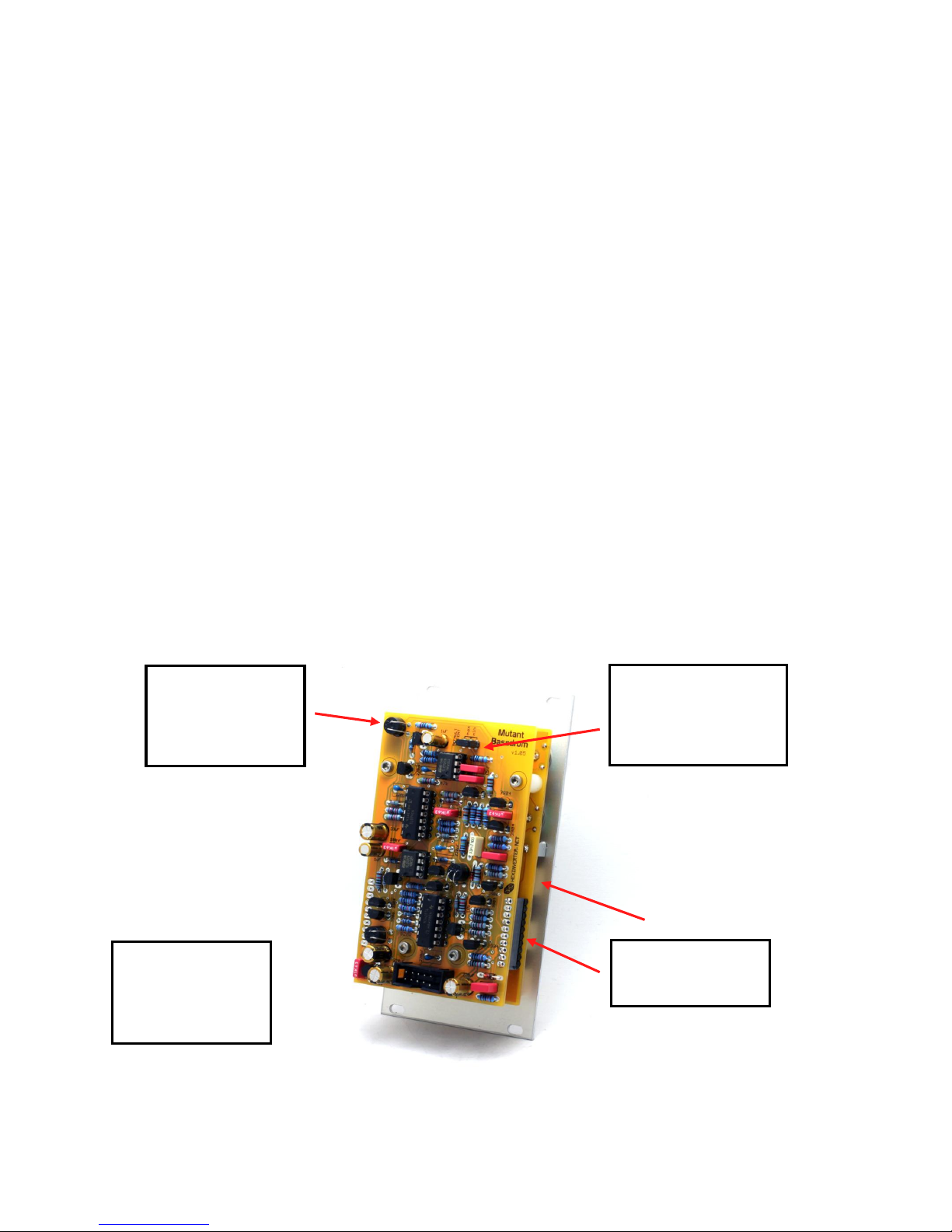
There are only two
10pin header pairs to
install on this build
The bottom header is
stacked only one PCB
layer deep –it lies
between the top and
middle PCB
This jumper selects the
DEFAULT ACCENT level. It
must be jumpered one way
or the other or the module
won’t work at all!
Make sure to install the
vactrols the right way
by lining up their dot
with the shaded area on
the PCB legend!

7.2.2014 Mutant Bassdrum assembly tips v1.05 PG3
hexinverter.net electronics, 2014
STEP 3: Control surface assembly
Putting together the control surface is arguably the most challenging part of this project so I recommend
taking your time. If you have been working for awhile, put down the soldering iron and go take a break and
clear your mind. I recommend this order of assembly:
1. Take the control PCB off of the PCB stack in order to work on it alone
2. Cut the little metal tab off each potentiometer (this depends on the type of pot you use)
3. Put everything loosely in place on the control PCB (don’t solder yet)
4. Place some washers/spacers on the pots to match the panel height
5. Remove the protective film on the panel and place it on the components
6. Finger tighten all of the nuts onto the panel. The jacks should be flat against the panel so they raise
off the PCB a bit.
7. Solder one leg of each pot and then reheat, pushing the pots flat against the PCB
8. Solder one leg of each jack and then reheat, pushing the jack flat against the panel
9. Solder one leg of each part and reheat, adjusting them to their final position on the panel
10. Once you are happy with the position of everything, solder everything!
11. Take a piece of component leg and use it to make a ground lead for each of the 3.5mm jacks.
Solder them in place.
The 3.5mm jacks should be
raised off of the PCB
surface a bit
I used a washer or two on
each pot to help match the
height of everything else
DON’T FORGET TO MAKE
THE GROUND LEADS
FOR THE JACKS!
This LED isn’t part of the
panel components so
instead it sits on the PCB. It
should be the same as the
purple DIST indicator LED
on the panel, but I’ve used
a different colour (clear)
here instead of purple since
it’s what I had laying
around.
Lay the tall electrolytic
capacitors on their sides,
otherwise they won’t fit
under the panel!

7.2.2014 Mutant Bassdrum assembly tips v1.05 PG4
hexinverter.net electronics, 2014
STEP 4: Test, then put it all together
I recommend testing the module before putting it all together. It takes awhile to take everything apart so you
want to correct any mistakes now before finalizing the whole build by putting on knobs and screwing the
PCB stack together. Plug the top PCB into the control PCB for testing but don’t install the screws and
spacers yet. You should be able to test everything with it just loosely assembled.
Once you’re confident everything works properly, assemble the PCB stack with the screws and spacers. Then
install the panel onto the PCB stack and tighten down all the control surface parts! This is what the finished
product looks like…
This screw adjusts the
maximum decay amount
the control/CV input adjust
to. See the USER MANUAL
for more information!


