HGST SA-7000 Parts list manual


FRU Replacement Guide Copyright
2
Notice
Copyright
The following paragraph does not apply to the United Kingdom or any country
where such provisions are inconsistent with local law: HGST a Western Digital
company PROVIDES THIS PUBLICATION "AS IS" WITHOUT WARRANTY
OF ANY KIND, EITHER EXPRESS OR IMPLIED, INCLUDING, BUT NOT
LIMITED TO, THE IMPLIED WARRANTIES OF MERCHANTABILITY
OR FITNESS FOR A PARTICULAR PURPOSE. Some states do not allow
disclaimer or express or implied warranties in certain transactions, therefore,
this statement may not apply to you.
This publication could include technical inaccuracies or typographical errors. Changes
are periodically made to the information herein; these changes will be incorporated
in new editions of the publication. HGST may make improvements or changes in any
products or programs described in this publication at any time.
It is possible that this publication may contain reference to, or information about,
HGST products (machines and programs), programming, or services that are not
announced in your country. Such references or information must not be construed to
mean that HGST intends to announce such HGST products, programming, or services
in your country.
Technical information about this product is available by contacting your local HGST
representative or on the Internet at: www.hgst.com/support
HGST may have patents or pending patent applications covering subject matter in
this document. The furnishing of this document does not give you any license to these
patents.
© 2015 HGST, Inc. All rights reserved.
HGST, a Western Digital company
3403 Yerba Buena Road
San Jose, CA 95135
Produced in the United States
Long Live Data™ is a trademark of HGST, Inc. and its affiliates in the United States
and/or other countries.
HGST trademarks are authorized for use in countries and jurisdictions in which HGST
has the right to use, market and advertise the brands.
Other product names are trademarks or registered trademarks of their respective
owners.
One MB is equal to one million bytes, one GB is equal to one billion bytes, one
TB equals 1,000GB (one trillion bytes) and one PB equals 1,000TB when referring
to storage capacity. Usable capacity will vary from the raw capacity due to object
storage methodologies and other factors.
References in this publication to HGST products, programs or services do not imply
that HGST intends to make these available in all countries in which HGST operates.
Product information is provided for information purposes only and does not constitute
a warranty.
Information is true as of the date of publication and is subject to change. Actual
results may vary. This publication is for general guidance only. Photographs may
show design models.

FRU Replacement Guide Contents
3
Contents
List of Figures..................................................................................................................................................... 5
List of Tables.......................................................................................................................................................8
Chapter 1 About this Guide................................................................................................................................ 9
1.1 Conventions........................................................................................................................................ 9
1.2 Storage Notations............................................................................................................................... 9
1.3 Admonitions......................................................................................................................................10
1.4 Related Documents...........................................................................................................................10
1.5 Weight...............................................................................................................................................10
Chapter 2 For More Information...................................................................................................................... 12
2.1 Points of Contact..............................................................................................................................12
Chapter 3 Controller Node Replaceable Units................................................................................................. 13
3.1 Warnings...........................................................................................................................................13
3.2 Chassis Replacement Procedure.......................................................................................................13
3.3 Hard Disk Drive Replacement Procedure........................................................................................30
3.4 Solid State Disk Replacement Procedure........................................................................................ 34
3.5 Power Supply Unit Replacement Procedure....................................................................................38
3.6 SFP+ Cable Replacement Procedure............................................................................................... 39
Chapter 4 Storage Node Replaceable Units......................................................................................................40
4.1 Warnings...........................................................................................................................................40
4.2 Chassis Replacement Procedure.......................................................................................................40
4.3 Hard Disk Drive Replacement Procedure........................................................................................57
4.4 Power Supply Unit Replacement Procedure....................................................................................60
4.5 MiniSAS 3M or 6M Cable Replacement Procedure....................................................................... 60
Chapter 5 Storage Interconnect Replaceable Units.......................................................................................... 63
5.1 Warnings...........................................................................................................................................63
5.2 Switch Replacement Procedure........................................................................................................63
5.3 Fan Replacement Procedure.............................................................................................................67
5.4 Power Supply Unit Replacement Procedure....................................................................................68
5.5 SFP+ 1G Module Replacement Procedure...................................................................................... 69
Chapter 6 Power Distribution Unit Replaceable Units.....................................................................................70
6.1 Warnings...........................................................................................................................................70
6.2 Power Distribution Unit Replacement Procedure............................................................................ 70
Chapter 7 Storage Enclosure Basic Field Replaceable Units........................................................................... 72
7.1 Visual Indicator and Field Replaceable Units Locations.................................................................72
7.2 Hard Disk Drive Replacement Procedure........................................................................................75

FRU Replacement Guide Contents
4
7.3 Power Cord Replacement Procedure............................................................................................... 88
7.4 MiniSAS Cable Replacement Procedure......................................................................................... 89
7.5 Rear Fan Replacement Procedure.................................................................................................... 90
7.6 Power Supply Unit Replacement Procedure....................................................................................92
7.7 I/O Canister Replacement Procedure............................................................................................... 95
Appendix A Troubleshooting.......................................................................................................................... 102
A.1 Field Replaceable Units.................................................................................................................102
Active Archive System Glossary...................................................................................................................103
A...........................................................................................................................................................103
B...........................................................................................................................................................103
C...........................................................................................................................................................103
D...........................................................................................................................................................103
E........................................................................................................................................................... 103
F........................................................................................................................................................... 104
G...........................................................................................................................................................104
H...........................................................................................................................................................104
I............................................................................................................................................................ 104
J............................................................................................................................................................104
K...........................................................................................................................................................104
L........................................................................................................................................................... 105
M..........................................................................................................................................................105
O...........................................................................................................................................................105
P........................................................................................................................................................... 105
R...........................................................................................................................................................105
S........................................................................................................................................................... 106
T........................................................................................................................................................... 106
U...........................................................................................................................................................106
V...........................................................................................................................................................106
W..........................................................................................................................................................106
X...........................................................................................................................................................107

FRU Replacement Guide List of Figures
5
List of Figures
Figure 1: Overview of Controller Node Chassis Replacement.........................................................................14
Figure 2: The Shutdown Button in the Commands Pane................................................................................. 16
Figure 3: Controller Node, Back.......................................................................................................................17
Figure 4: Controller Node, Front...................................................................................................................... 18
Figure 5: Controller Node, Back.......................................................................................................................18
Figure 6: Uninitialized Nodes........................................................................................................................... 19
Figure 7: The New Chassis Appears Under the FAILED List in the CMC..................................................... 21
Figure 8: The Old IPMI IP Address of the Node.............................................................................................24
Figure 9: Decommissioned Disks in the CMC.................................................................................................30
Figure 10: Decommissioned Disk Details from the CMC............................................................................... 31
Figure 11: Controller Node, Front.................................................................................................................... 31
Figure 12: Removing a Drive Carrier...............................................................................................................32
Figure 13: Decommissioned Disks in the CMC...............................................................................................34
Figure 14: Decommissioned Disk Details from the CMC............................................................................... 35
Figure 15: Controller Node, Front.................................................................................................................... 35
Figure 16: Removing a Drive Carrier...............................................................................................................36
Figure 17: Controller Node, Back, with PSU Status LEDs Highlighted..........................................................38
Figure 18: Controller Node SFP+ Ports........................................................................................................... 39
Figure 19: Overview of Storage Node Chassis Replacement...........................................................................41
Figure 20: A Storage Node Pane in the CMC..................................................................................................42
Figure 21: The Shutdown Button in the Commands Pane............................................................................... 43
Figure 22: Storage Node, Back.........................................................................................................................44
Figure 23: Storage Node, Front........................................................................................................................ 45
Figure 24: Storage Node, Back.........................................................................................................................45
Figure 25: Uninitialized Nodes......................................................................................................................... 46
Figure 26: The New Chassis Appears Under the FAILED List in the CMC................................................... 48
Figure 27: The Old IPMI IP Address of the Node...........................................................................................50

FRU Replacement Guide List of Figures
6
Figure 28: The Node with a Rebooted Chassis as Seen on the CMC.............................................................. 52
Figure 29: Storage Node Status in the CMC....................................................................................................55
Figure 30: Decommissioned Disks in the CMC...............................................................................................57
Figure 31: Drive Map Showing a Decommissioned Drive on a Storage Node................................................58
Figure 32: Storage Node, Front........................................................................................................................ 58
Figure 33: Removing a Drive Carrier...............................................................................................................58
Figure 34: Storage Node, Back, with PSU Status LEDs Highlighted.............................................................. 60
Figure 35: Storage Node MiniSAS Ports..........................................................................................................61
Figure 36: Removing the MiniSAS Cables...................................................................................................... 61
Figure 37: Location of Storage Interconnect Switches: [1]..............................................................................64
Figure 38: Switch Port Reservations.................................................................................................................66
Figure 39: Signal Cabling Scheme................................................................................................................... 66
Figure 40: Location of Storage Interconnect Switches: [1]..............................................................................67
Figure 41: Location of Storage Interconnect Switches: [1]..............................................................................68
Figure 42: Location of Storage Interconnect Switches: [1]..............................................................................69
Figure 43: System Enclosure Information........................................................................................................ 73
Figure 44: Rear Fan Order................................................................................................................................74
Figure 45: Sled HDD Order..............................................................................................................................74
Figure 46: Decommissioned Disks in the CMC...............................................................................................75
Figure 47: Decommissioned Disk Details from the CMC............................................................................... 76
Figure 48: A Storage Node Pane in the CMC..................................................................................................78
Figure 49: The Shutdown Button in the Commands Pane............................................................................... 78
Figure 50: Removing the Power Cords............................................................................................................ 79
Figure 51: Removing the MiniSAS Cables...................................................................................................... 80
Figure 52: Unlocking the I/O Canister............................................................................................................. 81
Figure 53: Removing the I/O Canister............................................................................................................. 81
Figure 54: Sled HDD Order..............................................................................................................................82
Figure 55: Sled Release Button........................................................................................................................ 83
Figure 56: Sled Release at 45 Degrees.............................................................................................................83

FRU Replacement Guide List of Figures
7
Figure 57: Removing the Sled.......................................................................................................................... 84
Figure 58: Sled Cover....................................................................................................................................... 85
Figure 59: Hard Disk Drive Carrier Buttons.................................................................................................... 86
Figure 60: Removing the Hard Disk Drive with Carrier..................................................................................86
Figure 61: Replacing the Failed Power Cord................................................................................................... 88
Figure 62: Replacing the Failed MiniSAS........................................................................................................89
Figure 63: Fan Release Button..........................................................................................................................90
Figure 64: Rear Fan.......................................................................................................................................... 91
Figure 65: A Storage Node Pane in the CMC..................................................................................................92
Figure 66: The Shutdown Button in the Commands Pane............................................................................... 92
Figure 67: Removing the Power Cord..............................................................................................................93
Figure 68: Removing the Power Supply Unit.................................................................................................. 94
Figure 69: A Storage Node Pane in the CMC..................................................................................................95
Figure 70: The Shutdown Button in the Commands Pane............................................................................... 96
Figure 71: Removing the MiniSAS Cables...................................................................................................... 97
Figure 72: Removing the Power Cords............................................................................................................ 98
Figure 73: Latch Handle Identification.............................................................................................................99
Figure 74: Latch Handle Clear of Rack Ear...................................................................................................100
Figure 75: Removing the I/O Canister............................................................................................................101

FRU Replacement Guide List of Tables
8
List of Tables
Table 1: Active Archive System Weight.......................................................................................................... 10
Table 2: Active Archive System Weight.......................................................................................................... 11
Table 3: Active Archive System Weight.......................................................................................................... 11
Table 4: Work Table with Sample MAC Addresses and Serial Bus Paths...................................................... 20
Table 5: Work Table with Sample Ethernet Port Names and NIC Array IDs..................................................23
Table 6: Work Table for Controller Node Chassis Replacement..................................................................... 28
Table 7: Work Table with Sample MAC Addresses and Serial Bus Paths...................................................... 47
Table 8: Work Table with Sample Ethernet Port Names and NIC Array IDs..................................................49
Table 9: Work Table for Storage Node Chassis Replacement......................................................................... 55

FRU Replacement Guide 1 About this Guide
9
Chapter
1
1 About this Guide
Topics:
•Conventions
•Storage Notations
•Admonitions
•Related Documents
•Weight
This guide provides procedures for customer replaceable units and field replaceable
units of the HGST Active Archive System.
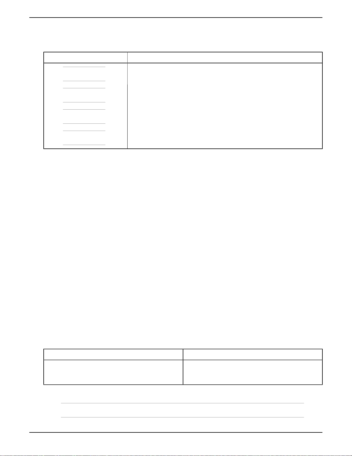
1.1 Conventions
Element Sample Notation
OS shell or Q-Shell commands (user input) rm -rf /tmp
OS shell or Q-Shell system output Installation successful!
Commands longer than one line are split with
"\"
q.dss.manage.setPermissions('/manage', \
[....])
User-supplied values ManagementNodeVirtualIPAddress or
<ManagementNodeVirtualIPAddress>
File and directory names The file aFile.txt is stored in /home/user.
Any graphical user interface label Click OK.
Keyboard keys and sequences To cancel the operation, press Ctrl+c.
Menu navigation in a GUI Navigate to Dashboard > Administration > Hardware > Servers.
1.2 Storage Notations
Convention Prefix Size (bytes)
KB kilobyte 1,000
KiB kibibyte 1,024
MB megabyte 1,000,000
MiB mebibyte 1,048,567
GB gigabyte 1,00,000,000
GiB gibibyte 1,073,741,824
TB terabyte 1,000,000,000,000
TiB tibibyte 1,099,511,627,776
•Sizes of disks are expressed with SI prefixes (kilo, mega, tera, peta, exa)
•Space, size of partitions and file systems are expressed with the binary prefixes (kibi, mebi, tebi, pebi, exbi)
• A comma (",") is used for digit grouping, for example 1,000 is 1 thousand.
• A period (".") is used as decimal mark, for example 12.5 %.
FRU Replacement Guide 1 About this Guide
10
1.3 Admonitions
Type Usage
Note:
Indicates extra information that has no specific hazardous or damaging
consequences.
Tip:
Indicates a faster or more efficient way to do something.
Caution:
Indicates an action that, if taken or avoided, may result in hazardous or damaging
consequences.
Warning:
Indicates an action that, if taken or avoided, may result in data loss or
unavailability.
1.4 Related Documents
For more information about the Active Archive System, please consult the following documents:
•The HGST Active Archive System Administration Guide explains how to use the Active Archive System interfaces
for executing system management, monitoring, and analytics tasks.
•The HGST Active Archive System API Guide provides a reference for the Active Archive System S3 API.
•The HGST Active Archive System FRU Replacement Guide provides procedures for replacing hardware components
of the Active Archive System.
•The HGST Active Archive System Installation Guide provides instructions for the installation of the Active Archive
System in the data center, and its initial bringup.
•The HGST Active Archive System Release Notes provide important information about changes, new features, and
known limitations.
•The HGST Active Archive System Site Requirements Document contains data center requirements for the Active
Archive System.
•The HGST Active Archive System Troubleshooting Guide provides help for issues you might encounter.
•The HGST Active Archive System Upgrade Guide provides instructions for software and firmware updates, and
system expansion.
For the latest or online version of any of these documents, visit http://www.hgst.com/support.
1.5 Weight
Rack:
The following table displays the weight of the Active Archive System:
Hardware Dimensions (Width x Height x Depth)
Active Archive System 2,250 lbs.
1,020 kg.
Table 1: Active Archive System Weight
Note: The weight mentioned previous is the total unpacked weight after delivery.

FRU Replacement Guide 1 About this Guide
11
Controller (SM 1028U-TR4T+):
The following table displays the weight of the Controller:
Hardware Dimensions (Width x Height x Depth)
Controller Net weight is 26lbs.
Gross weight is 41 lbs
Note: The gross weight of the controller
is based on the combined weight of
the server, accessories kit, rail kit, and
packaging
Table 2: Active Archive System Weight
Storage (SM 1018R-WC0R):
The following table displays the weight of the Storage server:
Hardware Dimensions (Width x Height x Depth)
Storage server Net weight is 25lbs.
Gross weight is 40lbs
Note: The gross weight of the storage
server is based on the combined weight
of the server, accessories kit, rail kit, and
packaging
Table 3: Active Archive System Weight

FRU Replacement Guide 2 For More Information
12
Chapter
2
2 For More Information
Topics:
•Points of Contact
This chapter provides points of contact for the Active Archive System.
2.1 Points of Contact
For further assistance with the Active Archive System, contact Elastic Storage Platforms support. Please be prepared
to provide the following information: serial number (S/N), product name, model number, and a brief description of the
issue.
Telephone:
Region Telephone Numbers Support Hours and Additional Information
United States/International 1-408-717-7766 24 hours a day, 7 days a week
North America 1-844-717-7766 24 hours a day, 7 days a week
Toll-free
Email:
Website:
www.hgst.com/support

FRU Replacement Guide 3 Controller Node Replaceable Units
13
Chapter
3
3 Controller Node Replaceable Units
Topics:
•Warnings
•Chassis Replacement Procedure
•Hard Disk Drive Replacement
Procedure
•Solid State Disk Replacement
Procedure
•Power Supply Unit
Replacement Procedure
•SFP+ Cable Replacement
Procedure
This section provides replacement procedures for the following parts in a Controller
Node:
• Chassis
• HDD
• SSD
• PSU
3.1 Warnings
Caution: Opening or removing the system cover when the system is powered on may expose you to a
risk of electric shock.
When replacing items from the inside of the chassis, ensure that you take precautions to prevent
electrostatic discharge (ESD).
Warning: Replace only one disk at a time on the Management Node.
3.2 Chassis Replacement Procedure
The Controller Node chassis is a SuperMicro DP 1U Server, 1028. Replacing the chassis replaces its NICs, CPU,
memory, motherboard, and fans, but not its disks.
Prerequisites
• Obtain a replacement Controller Node chassis from HGST.
• Obtain the virtual IP address of the Management Node.
• Obtain the IP addresses of the other (non failed) Controller Nodes.
• Obtain the admin password for the CMC.
• Obtain the root password.
• Fill in as much of the work table as possible before starting this procedure.
Required Tools
• Ladder
• Long Phillips-head screwdriver

FRU Replacement Guide 3 Controller Node Replaceable Units
14
Time Estimate: 3 hours.
Figure 1: Overview of Controller Node Chassis Replacement

FRU Replacement Guide 3 Controller Node Replaceable Units
15
A work table is provided at the end of this section for your convenience, to store all of the information needed for a
chassis replacement.
To replace a Controller Node chassis, proceed as follows:
1.
If the failed chassis is the Management Node chassis, fail over the Management Node to another Controller Node.
a) Open an SSH session to any Controller Node.
You must obtain the IP addresses of the Controller Node ahead of time.
b) Use the following command to determine the virtual IP address of the Management Node.
grep dmachine.amplistor.com /etc/hosts | grep -v 127.0.0.1 | awk '{print $1}'
The output of this command is the virtual IP address of the Management Node. For example,
172.16.63.154
c) Open an SSH session to the Management Node using the virtual IP address obtained in the previous substep.
d) Exit the OSMI menu.
The Linux prompt appears.
e) Copy or write down the hostname in the Linux prompt.
f) Log into the CMC.
g) Navigate to Dashboard > Administration > Hardware > Servers > Controller Nodes, and select the failed
Controller Node.
h) Compare the hostname of the failed node, as displayed in the CMC, to the hostname you saved from substep e.
i) If the failed node is the Management Node, fail over the Management Node to another Controller Node.
For instructions on how to fail over the Management Node, see Managing Hardware in the HGST Active
Archive System Administration Guide.
2.
Enable the location LED on the Controller Node.
a) In the CMC, navigate to Dashboard > Administration > Hardware > Servers > Controller Nodes.
b) Select the correct node.
c) In the Commands pane, click Location LED On.
A blue LED on its front and back panels is now blinking.
3.
Shut down the Controller Node from the CMC.
Note: Save the node's hostname in your worktable under Original Hostname of Node.
a) In the CMC, navigate to Dashboard > Administration > Hardware > Servers > Controller Nodes.
b) Select the desired Controller Node.

FRU Replacement Guide 3 Controller Node Replaceable Units
16
c) In the Commands pane, click Shutdown.
Figure 2: The Shutdown Button in the Commands Pane
d) Wait for the Status field to change to DONE.
4.
Go to the rack and identify the correct chassis by the blinking blue LED on its front and back panels.
5.
Remove the failed chassis from the rack.
a) At the front of the chassis, loosen the rack mounting screws.
b) At the back of the chassis, disconnect the five network cables connected to the ports labeled as follows in the
image below.
Important: Pull very gently on the pull tabs of the SFP+ cables, otherwise they might break.
Note: Check that the cables are labeled correctly, so that you can put them back in the same
order.
a. N1 (remove the SFP+ optical transceiver attached to the cable)
b. N2
c. N3
d. N4 (remove the SFP+ optical transceiver attached to the cable)

FRU Replacement Guide 3 Controller Node Replaceable Units
17
e. M2
Figure 3: Controller Node, Back
c) At the back of the chassis, disconnect the two power cords.
In the image above, the power cords are connected to the PSUs labeled P1 and P2.
d) At the back of the chassis, depress both rail slides inwards, and push the chassis towards the front of the rack,
until the rails pass the safety catch (about 3"/7.6cm).
e) At the front of the chassis, slowly slide the chassis out until you reach the pull-safety at the midway point (you
will hear a soft clicking sound, and feel the chassis "catch" on the rails).
f) Disengage the pull-safety on both sides of the chassis and slide it out until the split line of the two top covers.
Push the pull-safety on one side up, and the pull-safety on the other side down.
g) Continue to slowly slide the chassis out until you reach the pull-safety at the end point, and disengage it as you
did the earlier one.
h) Safely unmount the chassis from the rack and place it on a table.
Caution: A Controller Node chassis weighs about 50lbs. Ensure that you have sufficient
manpower to handle it safely.
Warning: Once you pull the chassis past the pull-safety, do not leave it hanging in the rack.
Otherwise, the rack rails may be damaged permanently.
6.
Move the two HDDs and the four SSDs from the failed chassis to the exact corresponding slots in the new
chassis.
Tip: Write down the disk serial number and slot location so that you can double-check that each
disk is seated in the correct slot post installation into the new chassis.
a) Remove each disk from its slot in the front bay of the failed chassis.

FRU Replacement Guide 3 Controller Node Replaceable Units
18
b) Install the disk into the corresponding slot in the new chassis.
Figure 4: Controller Node, Front
7.
Install the new chassis into the rack.
a) Mount the new chassis onto the rack slides and slide it into the rack.
Caution: Mounting the chassis is a two person task.
b) Tighten the rack mounting screws to secure the chassis to the rack.
c) Reconnect the five network cables to the chassis ports.
The network cables are labeled.
• Connect the cable labeled CNx.N1.SW1.Nxx (with SFP+ optical transceiver attached) to the port labeled
N1 in the image below.
• Connect the cable labeled CNx.N2.SW1.Nxx to the port labeled N2 in the image below.
• Connect the cable labeled CNx.N3.SW2.Nxx to the port labeled N3 in the image below.
• Connect the cable labeled CNx.N4.SW1.Nxx (with SFP+ optical transceiver attached) to the port labeled
N4 in the image below.
• Connect the cable labeled CNx.M2.SW1.Nxx to the port labeled M2 in the image below.
Figure 5: Controller Node, Back
d) Reconnect the power cords.
8. Get the MAC address of the new chassis IPMI NIC from the BIOS.
a) Connect a VGA monitor and USB keyboard to the new chassis.
b) Power on the new chassis.
The power button is located on the chassis front control panel.
c) At power up, press Del to enter into the system BIOS.
d) In the system BIOS, navigate to IPMI > BMC Network Configuration > .
e) Record Station MAC Address in your work table under IPMI MAC Address of Node.
f) Exit the BIOS without saving any changes by pressing the ESC.
The boot process continues.
g) Disconnect the VGA monitor and USB keyboard from the new chassis.

FRU Replacement Guide 3 Controller Node Replaceable Units
19
9.
Get the IP address and machine name (hostname) of the new chassis.
a) In the CMC, navigate to Dashboard > Administration > Hardware > Servers > Unmanaged Devices >
Uninitialized.
The new chassis appears in the list of uninitialized devices. This indicates that it has started successfully.
b) Write the value of Name into your work table, under Temporary Hostname of Node.
c) Write the value of Name without the PM- prefix into your work table, under MAC Address of Node.
d) Write the IP address into your work table, under Temporary IP Address of Node.
Figure 6: Uninitialized Nodes
10.
Get the bus-location-to-MAC-address mapping of the new chassis.
a) From the Management Node, open an SSH session to the new IP address of the Controller Node obtained in
the previous step.
Log in with username root and password rooter.
b) At the Linux prompt, run the following command:
for add in `ls /sys/devices/pci*/*/*/net/*/address`; do echo $add; cat
$add; done
The output of this command is similar to the example below.
/sys/devices/pci0000:00/0000:00:01.0/0000:01:00.0/net/eth0/address
00:25:90:fd:e8:7c
/sys/devices/pci0000:00/0000:00:01.0/0000:01:00.1/net/eth2/address
00:25:90:fd:e8:7d
/sys/devices/pci0000:00/0000:00:01.0/0000:01:00.2/net/eth3/address
00:25:90:fd:e8:7e
/sys/devices/pci0000:00/0000:00:01.0/0000:01:00.3/net/eth5/address
00:25:90:fd:e8:7f
/sys/devices/pci0000:80/0000:80:01.0/0000:81:00.0/net/eth1/address
90:e2:ba:7c:5a:fc
/sys/devices/pci0000:80/0000:80:01.0/0000:81:00.1/net/eth4/address
90:e2:ba:7c:5a:fd
/sys/devices/pci0000:80/0000:80:02.0/0000:82:00.0/net/eth6/address

FRU Replacement Guide 3 Controller Node Replaceable Units
20
90:e2:ba:7c:5d:a4
/sys/devices/pci0000:80/0000:80:02.0/0000:82:00.1/net/eth7/address
90:e2:ba:7c:5d:a5
root@nfsROOT:~#
The output of this command shows the serial bus path (for example, 0000:81:00.1) and the new MAC
address (for example, 90:e2:ba:7c:5a:fc).
Tip: As an alternative to the command above, you can use the command below to print only the
serial bus paths and MAC addresses in uppercase.
for add in `ls /sys/devices/pci*/*/*/net/*/address`; do echo -en
"`echo $add|sed 's/\// /g' | awk '{print $5}'`\t"; cat $add|tr 'a-f'
'A-F'; done
c) Fill in the serial bus path in ascending order in the Serial Bus Path column of the work table.
d) Fill in the MAC address corresponding to the serial bus path in ascending order in the MAC Address on the
New Chassis column of the work table.
For the sample output from the step above, the work table would look like this:
Serial Bus Path MAC Address on the New
Chassis
Ethernet Port Name
0000:01:00.0 00:25:90:fd:e8:7c eth0
0000:01:00.1 00:25:90:fd:e8:7d eth1
0000:01:00.2 00:25:90:fd:e8:7e eth2
0000:01:00.3 00:25:90:fd:e8:7f eth3
0000:81:00.0 90:e2:ba:7c:5a:fc eth4
0000:81:00.1 90:e2:ba:7c:5a:fd eth5
0000:82:00.0 90:e2:ba:7c:5d:a4 eth6
0000:82:00.1 90:e2:ba:7c:5d:a5 eth7
Table 4: Work Table with Sample MAC Addresses and Serial Bus Paths
e) Close the SSH session to the Controller Node.
You are now back in the SSH session to the Management Node.
11.
Get the machine GUID and device GUID of the new chassis.
a) On the Management Node, start the Q-Shell:
/opt/qbase3/qshell
b) Create a cloudAPI connection.
cloudapi = i.config.cloudApiConnection.find('main')
c) Retrieve the machine GUID for the new chassis, using the value of Temporary Hostname of Node in
uppercase, from the work table, for hostname_of_new_node in the command below:
machine_guid = cloudapi.machine.find(name='hostname_of_new_node')['result'][0]
Table of contents
Other HGST Storage manuals

HGST
HGST Travelstar Z5K500.B Product manual

HGST
HGST Ultrastar Data102 User manual

HGST
HGST HUS724040ALE640 User manual

HGST
HGST Touro Mobile User manual

HGST
HGST Ultrastar 7K2 Product manual

HGST
HGST CinemaStar C5K1000.B Product manual

HGST
HGST Travelstar 2.5-Inch Mobile 7200 RPM 7mm... User manual

HGST
HGST HUS724040ALS640 User manual
Popular Storage manuals by other brands

Seagate
Seagate Momentus 4200.3 product manual

Western Digital
Western Digital Ultrastar Data60 installation guide

Dell
Dell PowerVault MD3600f Series Getting started

Hitachi
Hitachi HUSSL4040BSS600 Quick installation guide

Commodore
Commodore VIC-1541 user manual

Huawei
Huawei OceanStor S2600 Command reference


