Hi-flying HF-LPB User manual
HF-LPB Low Power WiFi Module User Manual
Shanghai High-Flying Electronics Technology Co., Ltd
www.hi-flying.com
- 1 -
HF-LPB
Low Power WiFi Module User Maunal
V 1.1
Copyright
Hi-flying is a registered trademark of Hi-flying Incorporated. Copyright ©
2012 Hi-flying Incorporated. All rights reserved. No part of this publication
may be reproduced or distributed in any form or by any means, or stored
in a database or retrieval system, without the prior written permission of
the publisher. Hi-flyin
g
Incorporated reserves the ri
g
ht to make chan
g
es in
technical and product specifications without provisional notification. This
module is limited to OEM installation only and must not be sold to end-
users. OEM integrators must be instructed to ensure that the end-user has
no manual instructions to remove or install the device. The end-user can
not remove or install this module to any other devices.
Changes or modifications not expressly approved by the manufacturer
could void the user’s authority to operate the equipment.
If the FCC ID of the module cannot be seen when it is installed, then the
host label must include the text: Contains FCC ID: AZY-HF-LPB

HF-LPB Low Power WiFi Module User Manual
Shanghai High-Flying Electronics Technology Co., Ltd
www.hi-flying.com
- 2 -
Overview of Characteristic
Support IEEE802.11b/g/n Wireless Standards
Fully Self-Contained Serial-to-Wireless Functionality
Ultra-Low-Power for Battery Applications with Excellent Power Save Scheme
Support UART/SPI/USB/PWM/GPIO Data Communication Interface
Support Work As STA/AP/AP+STA Mode
Support Wi-Fi Direct
Support WPS Function
Support Wireless and Remote Firmware Upgrade Function
Support User-Defined Web Page Upload
Single +3.3V Power Supply
Smallest Size: 23mm x 32.5mm x2.7mm
FCC/CE Certificated
TABLE OF CONTENTS
LIST OF FIGURES...................................................................................................................................6
LIST OF TABLES ....................................................................................................................................7
HISTORY..................................................................................................................................................7
1.PRODUCT OVERVIEW ................................................................................................................8
1.1.General Description.................................................................................................................8
1.1.1Device Features..................................................................................................................8
1.1.2Device Paremeters.............................................................................................................9
1.1.3Key Application...................................................................................................................9
1.2.Hardware Introduction ..........................................................................................................10
1.2.1.Pins Definition...................................................................................................................10
1.2.2.Electrical Characteristics ..................................................................................................12
1.2.3.Mechanical Size................................................................................................................12
1.2.4.On-board Chip Antenna....................................................................................................13
1.2.5.Evaluation Kit....................................................................................................................14

HF-LPB Low Power WiFi Module User Manual
Shanghai High-Flying Electronics Technology Co., Ltd
www.hi-flying.com
- 3 -
1.2.6.Order Information..............................................................................................................15
1.3.Typical Application................................................................................................................16
1.3.1.Hardware Typical Application...........................................................................................16
2.FUNCTIONAL DESCRIPTION ..................................................................................................18
2.1.Wireless Networking .............................................................................................................18
2.1.1.Basic Wireless Network Based On AP (Infrastructure)....................................................18
2.1.2.Wireless Network Based On AP+STA..............................................................................18
2.1.3.Wi-Fi Direct Network.........................................................................................................19
2.2.Work Mode : Transparent Transmission Mode ..................................................................20
2.3.UART Frame Scheme ............................................................................................................21
2.3.1.UART Free-Frame............................................................................................................21
2.3.2.UART Auto-Frame............................................................................................................21
2.4.Encryption ..............................................................................................................................22
2.5.Network Protocal ...................................................................................................................22
2.6.Multi-TCP Link Connection...................................................................................................23
2.7.Power Save Scheme..............................................................................................................23
2.8.Parameters Configuration.....................................................................................................25
2.9.Firmware Update....................................................................................................................25
2.10.GPIO Function ....................................................................................................................25
3.OPERATION GUIDELINE ..........................................................................................................27
3.1.Configuration via Web Accessing........................................................................................27
3.1.1.Open Web Management Interface ...................................................................................27
3.1.2.System Page.....................................................................................................................27
3.1.3.Work Mode Page..............................................................................................................28
3.1.4.STA Setting Page.............................................................................................................28
3.1.5.AP Setting Page ...............................................................................................................29
3.1.6.Other Setting Page...........................................................................................................29
3.1.7.Account Management Page.............................................................................................30
3.1.8.Upgrade Software Page ...................................................................................................30
3.1.9.Restart Page.....................................................................................................................31
3.1.10.Restore Page................................................................................................................31
3.2.HF-LPB Usage Introduction..................................................................................................32
3.2.1.Software Debug Tools......................................................................................................32
3.2.2.Network Connection .........................................................................................................32
3.2.3.Default Parameter Setting ................................................................................................33
3.2.4.Module Debug ..................................................................................................................33
3.3.Typical Application Examples..............................................................................................34
3.3.1.Wireless Control Application.............................................................................................34
3.3.2.Remote Management Application ....................................................................................35
3.3.3.Transparent Serial Port Application..................................................................................35
4.AT+INSTRUCTION INTRODUCTION ......................................................................................36
4.1.Configuration Mode...............................................................................................................36

HF-LPB Low Power WiFi Module User Manual
Shanghai High-Flying Electronics Technology Co., Ltd
www.hi-flying.com
- 4 -
4.1.1.Switch to Configuration Mode...........................................................................................36
4.2.AT+ Instruction Set Overview...............................................................................................37
4.2.1.Instruction Syntax Format.................................................................................................37
4.2.2.AT+ Instruction Set...........................................................................................................38
4.2.2.1.AT+E .............................................................................................................................39
4.2.2.2.AT+WMODE .................................................................................................................40
4.2.2.3.AT+ENTM .....................................................................................................................40
4.2.2.4.AT+TMODE...................................................................................................................40
4.2.2.5.AT+MID.........................................................................................................................40
4.2.2.6.AT+VER........................................................................................................................41
4.2.2.7.AT+RELD......................................................................................................................41
4.2.2.8.AT+Z .............................................................................................................................41
4.2.2.9.AT+H.............................................................................................................................41
4.2.2.10.AT+UART..................................................................................................................41
4.2.2.11.AT+ UARTF...............................................................................................................42
4.2.2.12.AT+ UARTFT.............................................................................................................42
4.2.2.13.AT+ UARTFL.............................................................................................................43
4.2.2.14.AT+ UARTTE.............................................................................................................43
4.2.2.15.AT+ SEND.................................................................................................................43
4.2.2.16.AT+ RECV.................................................................................................................43
4.2.2.17.AT+ PING..................................................................................................................44
4.2.2.18.AT+NETP ..................................................................................................................44
4.2.2.19.AT+ TCPLK ...............................................................................................................44
4.2.2.20.AT+ TCPTO...............................................................................................................45
4.2.2.21.AT+TCPDIS...............................................................................................................45
4.2.2.22.AT+WSSSID..............................................................................................................45
4.2.2.23.AT+WSKEY...............................................................................................................46
4.2.2.24.AT+ WANN................................................................................................................46
4.2.2.25.AT+ WSMAC.............................................................................................................46
4.2.2.26.AT+ WSLK.................................................................................................................47
4.2.2.27.AT+ WSLQ ................................................................................................................47
4.2.2.28.AT+WSCAN...............................................................................................................47
4.2.2.29.AT+ LANN .................................................................................................................47
4.2.2.30.AT+WAP....................................................................................................................48
4.2.2.31.AT+WAKEY...............................................................................................................48
4.2.2.32.AT+WAMAC..............................................................................................................49
4.2.2.33.AT+WADHCP............................................................................................................49
4.2.2.34.AT+WEBSWITCH .....................................................................................................49
4.2.2.35.AT+PSPAR................................................................................................................49
4.2.2.36.AT+MSLP..................................................................................................................50
4.2.2.37.AT+MSOPT...............................................................................................................50
4.2.2.38.AT+TSPAR................................................................................................................51
4.2.2.39.AT+WRMID ...............................................................................................................51

HF-LPB Low Power WiFi Module User Manual
Shanghai High-Flying Electronics Technology Co., Ltd
www.hi-flying.com
- 5 -
4.2.2.40.AT+ASWD.................................................................................................................51
5.PACKAGE INFORMATION........................................................................................................52
5.1.Recommended Reflow Profile..............................................................................................52
5.2.Device Handling Instruction (Module IC SMT Preparation)...............................................52
5.3.Shipping Information.............................................................................................................53
APPENDIX A: HW REFERENCE DESIGN......................................................................................54
APPENDIX B: CONTACT INFORMATION ......................................................................................55
1 STANDARDS AND REGULATORY COMPLIANCE .........................................................................56
1.2Standards and certification...................................................................................................56
1.3FCC certification requirements. ...........................................................................................56
1.4FCC RF exposure requirements...........................................................................................58

HF-LPB Low Power WiFi Module User Manual
Shanghai High-Flying Electronics Technology Co., Ltd
www.hi-flying.com
- 6 -
LIST OF FIGURES
Figure 1.HF-LPB Demo ..................................................................................................................10
Figure 2.HF-LPB Pins Map.............................................................................................................10
Figure 3.HF-LPB Mechanical Dimension........................................................................................13
Figure 4.HF-LPB PCB Symbol Size................................................................................................13
Figure 5.Suggested Module Placement Region.............................................................................13
Figure 6.HF-LPB Evaluation Kit......................................................................................................14
Figure 7.HF-LPB Order Information................................................................................................15
Figure 8.HF-LPB Hardware Typical Application.............................................................................16
Figure 9.HF-LPB Basic Wireless Network Structure......................................................................18
Figure 10.HF-A11 AP+STA Network Structure ................................................................................19
Figure 11.HF-LPB 1:1 P2P Networking...........................................................................................19
Figure 12.HF-LPB 1:N P2P Networking ..........................................................................................20
Figure 13.HF-LPB Concurrent Operation Networking......................................................................20
Figure 14.Multi-TCP Link Data Transmition Structure......................................................................23
Figure 15.Open Web Management page .........................................................................................27
Figure 16.System Web Page............................................................................................................28
Figure 17.Work Mode Page..............................................................................................................28
Figure 18.STA Setting Page.............................................................................................................29
Figure 19.AP Setting Page ...............................................................................................................29
Figure 20.Other Setting Page...........................................................................................................30
Figure 21.Account Page ...................................................................................................................30
Figure 22.Upgrade SW page............................................................................................................31
Figure 23.Restart Page.....................................................................................................................31
Figure 24.Restore Page....................................................................................................................32
Figure 25.STA Interface Debug Connection.....................................................................................32
Figure 26.AP Interface Debug Connection.......................................................................................33
Figure 27.“CommTools” Serial Debug Tools....................................................................................33
Figure 28.“TCPUDPDbg” Tools Create Connection.........................................................................33
Figure 29.“TCPUDPDbg” Tools Setting............................................................................................34
Figure 30.“TCPUDPDbg” Tools Connection.....................................................................................34
Figure 31.Wireless Control Application.............................................................................................34
Figure 32.Remote Management Application ....................................................................................35
Figure 33.Transparent Serial Port Application..................................................................................35
Figure 34.HF-LPB Default UART Port Parameters ..........................................................................36
Figure 35.Switch to Configuration Mode...........................................................................................36
Figure 36.”AT+H” Instruction for Help...............................................................................................37
Figure 37.Reflow Soldering Profile ...................................................................................................52
Figure 38.Shipping Information.........................................................................................................53

HF-LPB Low Power WiFi Module User Manual
Shanghai High-Flying Electronics Technology Co., Ltd
www.hi-flying.com
- 7 -
LIST OF TABLES
Table 1 HF-LPB Module Technical Specifications...............................................................................9
Table 2 HF-LPB Pins Definition..........................................................................................................10
Table 4 HF-LPB Evaluation Kit Interface Description ........................................................................15
Table 5 HF-LPB IP Stack Features....................................................................................................22
Table 6 Difference Between Deelp Sleep And Standby Mode ..........................................................24
Table 7 Power Consumption with Different Power Save Mode.........................................................24
Table 8 HF-LPB GPIO Pin Mapping Table ........................................................................................25
Table 9 HF-LPB Web Access Default Setting....................................................................................27
Table 10 Error Code Describtion........................................................................................................38
Table 11 AT+ Instruction Set List.......................................................................................................38
Table 12 Reflow Soldering Parameter .................................................................................................52
HISTORY
Ed. V1.0 Created on 1-29-2013.
Ed. V1.1 02-24-2013. Update AT command contents.

HF-LPB Low Power WiFi Module User Manual
Shanghai High-Flying Electronics Technology Co., Ltd
www.hi-flying.com
- 8 -
1.PRODUCT OVERVIEW
1.1. General Description
The HF-LPB is a fully self-contained small form-factor, single stream, 802.11b/g/n Wi-Fi module,
which provide a wireless interface to any equipment with a Serial/SPI/USB interface for data
transfer.HF-LPB integrate MAC, baseband processor, RF transceiver with power amplifier in hardware
and all Wi-Fi protocol and configuration functionality and networking stack, in embedded firmware to
make a fully self-contained 802.11b/g/n Wi-Fi solution for a variety of applications.
HF-LPB support AP+STA wireless networking and support Wi-Fi Direct. HF-LPB also provides
wireless and remote firmware upgrade, which satisfied all kinds of application requirement. HF-LPB
support user defined Web page and can revise the data communication protocol, which reduce much
customer’s software development and customization work.
The HF-LPB employs the world's lowest power consumption embedded architecture. It has been
optimized for all kinds of client applications in the home automation, smart grid, handheld device,
personal medical application and industrial control that have lower data rates, and transmit or receive
data on an infrequent basis.
The HF-LPB integrates all Wi-Fi functionality into a low-profile, 23x32.5x 2.7mm SMT module package
that can be easily mounted on main PCB with application specific circuits.
1.1.1 Device Features
zSingle stream Wi-Fi @ 2.4 GHz with support for WEP security mode as well as WPA/WPA2
zFully self-contained serial-to-wireless functionality.
zUltra-low-power operation with all kinds of power-save modes.
zIncludes all the protocol and configuration functions for Wi-Fi connectivity.
zSupport STA/AP/AP+STA Mode
zSupport Wi-Fi Direct Mode
zSupport WPS
zSupport Wireless and Remote Firmware Upgrade Function
zSupport User-Defined Web Page Upload
zIntegrated chip antenna options.
zCompact surface mount module 23mm x 32.5mm x 2.7mm.
zFull IPv4 and IPv6 stack.
zLow power RTOS and drivers.
zFCC Certified.
zRoHS and CE compliant.
zSingle supply – 3.3V operation.

HF-LPB Low Power WiFi Module User Manual
Shanghai High-Flying Electronics Technology Co., Ltd
www.hi-flying.com
- 9 -
1.1.2 Device Paremeters
Table 1 HF-LPB Module Technical Specifications
Class Item Parameters
Wireless
Parameter
s
Certification FCC/CE
Wireless standard 802.11 b/g/n
US Frequency range 2.412GHz-2.462GHz
EU Frequency range 2.412GHz-2.472GHz
Transmit Power
802.11b: +18dBm (Max.)
802.11g: +14dBm (Max.)
802.11n: +11dBm (Max.)
Configurable
Receiver Sensitivity 802.11b: -93 dBm (@11Mbps ,CCK)
802.11g: -85 dBm (@54Mbps, OFDM)
802.11n: -82 dBm (@HT20, MCS7)
Antenna Option Internal:On-board PCB antenna
Hardware
Parameter
s
Data Interface UART
USB, SPI, PWM…
Others: GPIO, ADC/DAC, RTC…
Operating Voltage 3.1~3.6V
Operating Current
Peak [Continuous TX]: ~200mA
Normal [WiFi ON/OFF, DTIM=100ms]:
Average. ~5mA, Peak: 200mA
Deep Sleep: [WiFi OFF]: ~2mA
Standby [WiFi Shutdown]: <2uA
Operating Temp. -40℃- 85℃
Storage Temp. -45℃- 125℃
Dimensions and Size 23mm×32.5mm×2.7mm
Software
Parameter
s
Network Type STA /AP/STA+AP/Wi-Fi Direct
Security
Mechanisms WEP/WPA-PSK/WPA2-PSK/WPS
Encryption WEP64/WEP128/TKIP/AES
Update Firmware Local Wireless, Remote
Customization Web Page Upgrade
Support SDK for application develop
Serial command AT+instruction set
Network Protocol IPv4, IPv6,TCP/UDP/FTP/HTTP
User Configuration AT+instruction set. Android/ iOS
1.1.3 Key Application
zRemote equipment monitoring
zAsset tracking and telemetry
zSecurity
zIndustrial sensors and controls
zHome automation
zMedical devices
HF-LPB Low Power WiFi Module User Manual
Shanghai High-Flying Electronics Technology Co., Ltd
www.hi-flying.com
- 10 -
1.2. Hardware Introduction
Figure 1. HF-LPB Demo
1.2.1. Pins Definition
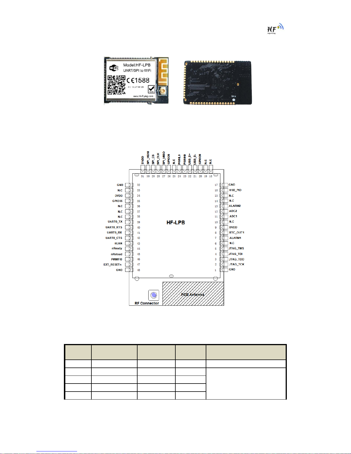
Figure 2. HF-LPB Pins Map
Table 2 HF-LPB Pins Definition
Pin Describtion Net Name Signal
Type Comments
1,17,32,48 Ground GND Power
2 JTAG Function JTAG_TCK I, PU JTAG/Debug functional pin,
No connect if not use.
3 JTAG Function JTAG_TDO O
4 JTAG Function JTAG_TDI I,PU
5 JTAG Function JTAG_TMS I,PU

HF-LPB Low Power WiFi Module User Manual
Shanghai High-Flying Electronics Technology Co., Ltd
www.hi-flying.com
- 11 -
6 N.C No connect
7 RTC Input 1 ALARM1 I.PD GPIO7, Sleep_RQ Pin
8 RTC Output 1 RTC_OUT1 O GPIO8, Sleep_ON Pin
9 +3.3V Power DVDD Power
10 N.C No connect
11 A/D Input 1 ADC1 I/O,PD GPIO11, No connect if not use.
12 A/D Input 2 ADC2 I/O,PD GPIO12, No connect if not use.
13 RTC Input 2 ALARM2 I,PD GPIO13, No connect if not use.
14 N.C No connect
15 N.C No connect
16 USB 5V Detect USB_PIO I/O GPIO16, No connect if not use.
18 N.C No connect
19 N.C No connect
20 GPIO GPIO20 I/O,PD GPIO20, No connect if not use.
21 USB Interface USB- I/O 90 ohm Diff. Line
22 USB Interface USB+ I/O 90 ohm Diff. Line
23 PWM Output0+ PWMH0 O GPIO23, No connect if not use.
24 PWM Output0- PWML0 O GPIO24, No connect if not use.
25 N.C No connect
26 GPIO GPIO26 I/O,PD GPIO26, No connect if not use.
27 SPI Interface SPI_MISO I/O, PU No connect if not use.
28 SPI Interface SPI_CLK I/O, PU No connect if not use.
29 SPI Interface SPI_CS I/O,PU No connect if not use.
30 SPI Interface SPI_MOSI I/O.PD No connect if not use.
31 +3.3V Power DVDD Power
33 N.C No connect
34 +3.3 Power DVDD Power
35 GPIO GPIO35 I/O,PD GPIO35, WPS functional pin
36 N.C No connect
37 N.C No connect
38 N.C No connect
39 UART0 UART0_TX O, PD UART Communication Pin
40 UART0 UART0_RTS I/O,PD UART Communication Pin
41 UART0 UART0_RX I,PD UART Communication Pin
42 UART0 UART0_CTS I/O, PD UART Communication Pin
43 Wi-Fi Status nLink O,PU “0”- Wi-Fi Linked
“1”- No WIFI Linked
No connect if not use.
44 Module Boot Up
Indicator nReady O,PU “0” – Boot-up OK;
“1” – Boot-up No OK;
No connect if not use.;
45 Restore
Configuration nReload I,PU Module will restore factory
default after set this pin “0” more
than 1s, then set “1”.
No connect if not use;
46 PWM Fault Input0 PWMFI0 GPIO46, No connect if not use.
47 Module Reset EXT_RESETn I,PU “Low” effective reset input.
HF-LPB Low Power WiFi Module User Manual
Shanghai High-Flying Electronics Technology Co., Ltd
www.hi-flying.com
- 12 -
1.2.2. Electrical Characteristics
Absolute Maximum Ratings:
Parameter Condition Min. Typ. Max. Unit
Storage temperature range -45 125 °C
Maximum soldering temperature IPC/JEDEC J-STD-020 260 °C
Supply voltage 0 3.8 V
Voltage on any I/O pin 0 3.3 V
ESD (Human Body Model HBM) TAMB=25°C 2 KV
ESD (Charged Device Model, CDM) TAMB=25°C 1 KV
Power Supply & Power Consumption:
Parameter Condition Min. Typ. Max. Unit
Operating Supply voltage 3.1 3.3 3.8 V
Supply current, peak Continuous Tx 200 mA
Supply current, IEEE PS DTIM=100ms 5 mA
Output high voltage Sourcing 6mA 2.8 V
Output low voltage Sinking 6mA 0.2 V
Input high voltage 2.2 V
Input low voltage 0.8 V
Input leakage current +/-25 nA
Analog input range 0 3 V
Analog output range 0 3 V
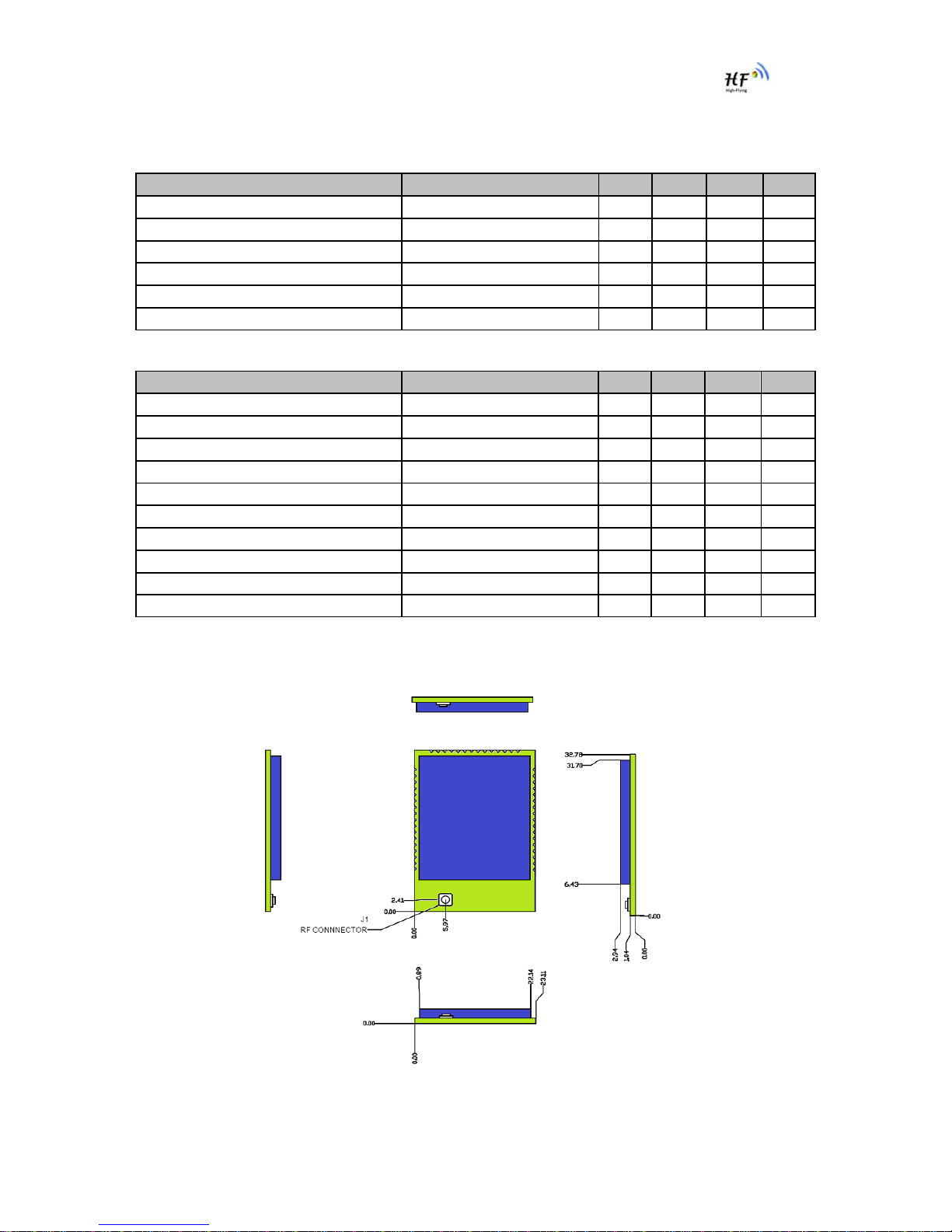
1.2.3. Mechanical Size
HF-LPB modules physical size (Unit: mm)as follows:

HF-LPB Low Power WiFi Module User Manual
Shanghai High-Flying Electronics Technology Co., Ltd
www.hi-flying.com
- 13 -
Figure 3. HF-LPB Mechanical Dimension
HF-LPB Module PCB symbol size (mm) as follows:
Figure 4. HF-LPB PCB Symbol Size
1.2.4. On-board Chip Antenna
HF-LPB module support internal on-board chip antenna option. When customer select internal
antenna, you shall comply with following antenna design rules and module location suggestions:
¾For customer PCB, RED color region (8.3x18.4mm) can’t put componet or paste GND net;
¾Antenna must away from metal or high components at least 10mm;
¾Antenna can’t be shieldedby any meal enclosure; All cover, include plastic, shall away from
antenna at least 10mm;
Figure 5. Suggested Module Placement Region
HF-LPB Low Power WiFi Module User Manual
Shanghai High-Flying Electronics Technology Co., Ltd
www.hi-flying.com
- 14 -
High-Flying suggest HF-LPB module better locate in following region at customer board, which to
reduce the effect to antenna and wireless signal, and better consult High-Flying technical people when
you structure your module placement and PCB layout.
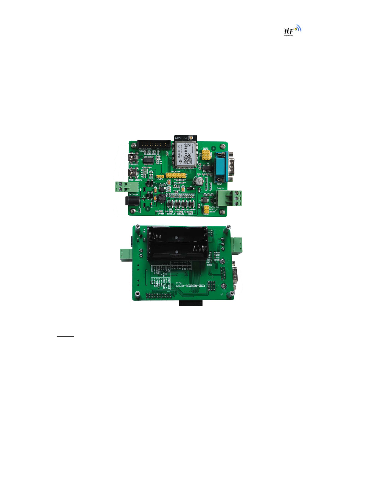
1.2.5. Evaluation Kit
High-Flying provides the evaluation kit to promote user to familiar the product and develop the detailed
application. The evaluation kit shown as below, user can connect to HF-LPB module with the RS-232
UART, RS485, USB (Internal UART-USB convetor) or Wireless port to configure the parameters,
manage the module or do the some functional tests.
Figure 6. HF-LPB Evaluation Kit
Notes: User need download USB - UART port driver from High-Flying web or contact with technical
support people for more detail.
The external interface description for evaluation kit as follows:
HF-LPB Low Power WiFi Module User Manual
Shanghai High-Flying Electronics Technology Co., Ltd
www.hi-flying.com
- 15 -
Table 4 HF-LPB Evaluation Kit Interface Description
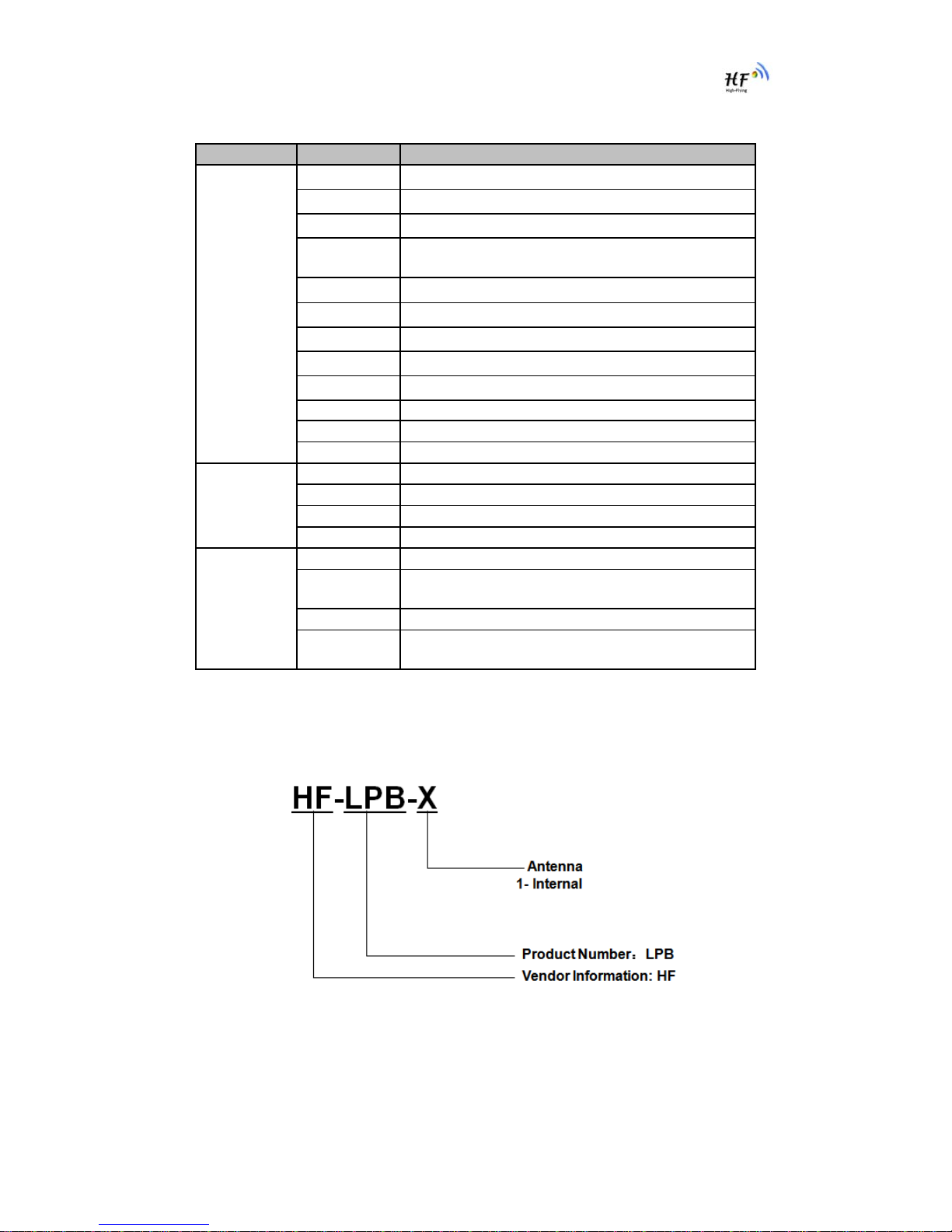
1.2.6. Order Information
Base on customer detailed requirement, HF-LPB series modules provide different variants and
physical type for detailed application.
Figure 7. HF-LPB Order Information
Function Name Description
External
Interface COM1 Main data/command RS-232 interface
RS485 Main data/command RS-485 interface
JTAG JTAG data debug interface (Not for user use)
USB2TTL UART to USB debug interface. (For PC without
RS232, need load driver). Can be Power input.
USB DEBUG USB2.0 data interface.
DC Jack DC jack for power in, 5~18V input.
DC5-18V DC jack for power in, 5~18V input.
BAT 2 Li-Battery Power Supply.
EXT PORT HF-LPB GPIO function extend interface connector
JMP1,JMP2 Reserved, No Jumper required.
JMP3 4Pin USB or RS232 Jumper. Left jump select USB.
JMP6 3Pin RS485 Jumper. No jump selects RS232.
LED Power 3.3V Power Indicator
nLink nLink -WiFi LINK Indicator
nReady nReady – Module Bootup Ready Indicator
Sleep_ON Sleep_ON-Module asleep or awake Indicator
Button nReset Used to reset the module.
nReload Restore factory default configuration after push this
pin more than 3s.
WPS WPS Button
Sleep_RQ Pin Sleep Control button, more than 1s to put
module in standby mode.
HF-LPB Low Power WiFi Module User Manual
Shanghai High-Flying Electronics Technology Co., Ltd
www.hi-flying.com
- 16 -
1.3. Typical Application
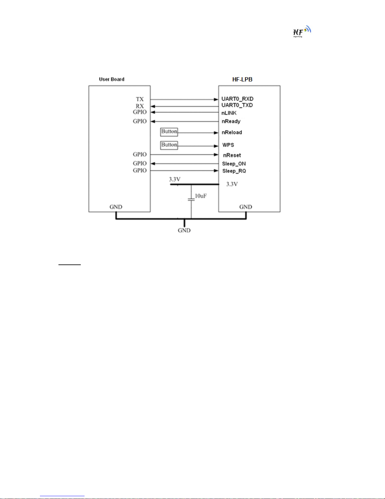
1.3.1. Hardware Typical Application
Figure 8. HF-LPB Hardware Typical Application
Notes:
nReset- Module hardware reset signal. Input. Logics “0” effective.
There is pull-up resister internal and no external pull-up required. When module power up or some
issue happened, MCU need assert nRST signal “0” at least 10ms, then set” 1” to keep module fully
reset.
nLink- Module WIFI connection status indication. Output.
When module connects to AP (AP associated), this pin will output “0”. This signal used to judge if
module already at WiFi connection status. Thers is pull-up resister internal and no external pull-up
required. If n Link function not required, can leave this pin open.
nReady- Module boot up ready signal. Output. Logics “0” effective.
The module will output “0” after normal boot up. This signal used to judge if module finish boot up and
ready for application or working at normal mode. If nReady function not required, can leave this pin
open.
WPS – module auto-negotiation with AP and acquire password and build link
User can de-asser this pin low ”0”, after 500ms, then asser this pin high “1” to enable the auto
negotiation.if AP also push its WPS button, then Module and AP will start auto-negotiation and

HF-LPB Low Power WiFi Module User Manual
Shanghai High-Flying Electronics Technology Co., Ltd
www.hi-flying.com
- 17 -
module acquire password and build link. Next time, module will link with same AP without auto-
negotiation required. User can use “AT+WSSSID” and “AT+WSKEY” command to query SSID and
password.
nReload- Module restore to factory default configuration.Input. Logics “0” effective.
User can de-assert nReload signal “0” more than 3s through button or MCU pin, then release, module
will restore to factory default configuration and re-start boot up process. Thers is pull-up resister
internal and no external pull-up required. If nReload function not required, can leave this pin open.
Sleep-RQ- Module Pin Sleep Control. Input.
The user should de-assert this pin low “0”, after 1’s assert to high ”1” to put the module to sleep status.
Also at the deep sleep/standby mode, user can de-assert this pin low “0”, after 1’s assert to high ”1”
to put the module to wake up the module. If user doesn't use pin sleep function, can leave this pin
open.
Sleep-ON- Module Pin Sleep Indicator. Output.
This pin is used to indicate that the module is asleep (Module output “0”) or awake (Module output “1”)
status. If user doesn't use pin sleep function, can leave this pin open.
UART0_TXD/RXD- UART port data transmit and receive signal.
HF-LPB Low Power WiFi Module User Manual
Shanghai High-Flying Electronics Technology Co., Ltd
www.hi-flying.com
- 18 -
2.FUNCTIONAL DESCRIPTION
2.1. Wireless Networking
HF-LPB module can be configured as both wireless STA and AP base on network type. Logically
there are two interfaces in HF-LPB. One is for STA, and another is for AP. When HF-LPB works as AP,
other STA equipments are able to connect to wireless LAN via HF-LPB module. Wireless Networking
with HF-LPB is very flexible.
Notes:
AP: that is the wireless Access Point, the founder of a wireless network and the centre of the network
nodes. The wireless router we use at home or in office may be an AP.
STA: short for Station, each terminal connects to a wireless network (such as laptops, PDA and other
networking devices) can be called with a STA device.
2.1.1. Basic Wireless Network Based On AP (Infrastructure)
Infrastructure: it’s also called basic network. It built by AP and many STAs which join in.
The characters of network of this type are that AP is the centre, and all communication between STAs
is transmitted through the AP. The figure following shows such type of networking.
Figure 9. HF-LPB Basic Wireless Network Structure
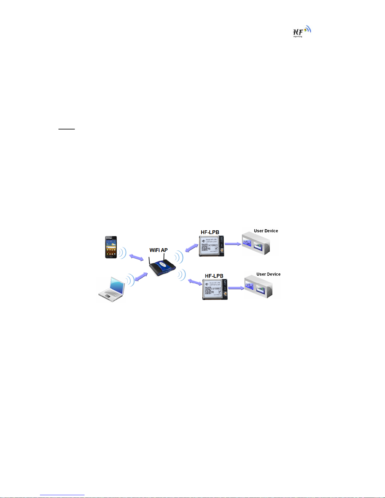
2.1.2. Wireless Network Based On AP+STA
HF-LPB module support AP+STA network mode, means module support one AP interface and one
STA interface at the same time, as following figure,

HF-LPB Low Power WiFi Module User Manual
Shanghai High-Flying Electronics Technology Co., Ltd
www.hi-flying.com
- 19 -
Figure 10. HF-A11 AP+STA Network Structure
When module enables AP+STA function, Module’s STA interface can connect with router and connect
to TCP server in the network. At the same time, module’s AP interface is also active and permit
phone/PAD to connect through TCPB, then phone/PAD can control user device and and setting the
module parameters,
The advantage of AP+STA mode is:
¾Users can easily setting and track user device through Phone/PAD and not change the
orginal network setting.
¾Users can easily setting module’s parameters through WiFi when module works as STA
mode.
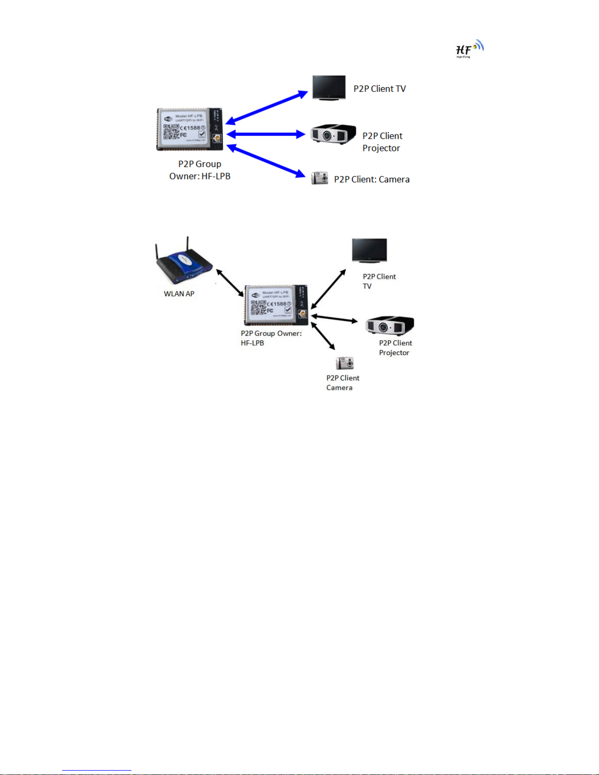
2.1.3. Wi-Fi Direct Network
Wi-Fi Direct standard permits the wireless connection without AP router. Like blue tooth, this standard
use point to point interconnection and all devices connect each other and transmit data withour router.
HF-LPB module support following Wi-Fi Direct networking:
¾1:1 P2P Networking;
¾1:N P2P Networking;
¾Concurrent Operation Networking;
Figure 11. HF-LPB 1:1 P2P Networking
HF-LPB Low Power WiFi Module User Manual
Shanghai High-Flying Electronics Technology Co., Ltd
www.hi-flying.com
- 20 -
Figure 12. HF-LPB 1:N P2P Networking
Figure 13. HF-LPB Concurrent Operation Networking
2.2. Work Mode : Transparent Transmission Mode
HF-LPB module support serial interface transparent transmission mode. The benefit of this mode is
achieves a plug and play serial data port, and reduces user complexity furthest. In this mode, user
should only configure the necessary parameters. After power on, module can automatically connect to
the default wireless network and server.
As in this mode, the module's serial port always work in the transparent transmission mode, so users
only need to think of it as a virtual serial cable, and send and receive data as using a simple serial. In
other words, the serial cable of users’ original serial devices is directly replaced with the module; user
devices can be easy for wireless data transmission without any changes.
The transparent transmission mode can fully compatible with user’s original software platform and
reduce the software development effort for integrate wireless data transmission.
The parameters which need to configure include:
¾Wireless Network Parameters
Wireless Network Name(SSID)
Security Mode
Table of contents
Other Hi-flying Network Card manuals

Popular Network Card manuals by other brands

ZyXEL Communications
ZyXEL Communications M-102 release note

TRENDnet
TRENDnet TEG-10GECTX Quick installation guide

Emulex
Emulex OM1 Cabling guide

ATTO Technology
ATTO Technology Low-Profile SAS RAID Adapter R380 Specification sheet

ATTO Technology
ATTO Technology FastFrame NS11 Getting started guide

Sonnet
Sonnet PRESTO GIGABIT quick start guide


