Hi-P T Series Parts list manual
3A6823A
EN
Instructions-Parts
T-Series Intensifier
Pump
Pneumatic pump for generating high pressure for hydrostatic tests and
hydraulically-operated systems. For professional use only.
See page 3 for model information, including maximum working pressures.
Important Safety Instructions
Read all warnings and instructions in this manual
before using the equipment. Save all instructions.
Approvals
23A6823A
Contents
Approvals . . . . . . . . . . . . . . . . . . . . . . . . . . . . . . . . . 2
Models . . . . . . . . . . . . . . . . . . . . . . . . . . . . . . . . . . . 3
6.0 Inch Motor . . . . . . . . . . . . . . . . . . . . . . . . . . . 3
7.5 Inch Motor . . . . . . . . . . . . . . . . . . . . . . . . . . . 4
Warnings . . . . . . . . . . . . . . . . . . . . . . . . . .5
Installation . . . . . . . . . . . . . . . . . . . . . . . . . . . . . . . . 7
Grounding . . . . . . . . . . . . . . . . . . . . . . . . . . . . . . 7
Required Accessories . . . . . . . . . . . . . . . . . . . . . 7
Flush Before Using Equipment . . . . . . . . . . . . . . 7
Typical Installation . . . . . . . . . . . . . . . . . . . . . . . 8
Mount the Pump and Connect Fluid Supply . . . . 9
Connect Pneumatic Supply . . . . . . . . . . . . . . . . . 9
Connect Fluid Outlet . . . . . . . . . . . . . . . . . . . . . . 9
Operation . . . . . . . . . . . . . . . . . . . . . . . . . . . . . . . . 10
Pressure Relief Procedure . . . . . . . . . . . . . . . . 10
Flush the Equipment . . . . . . . . . . . . . . . . . . . . . 10
Prime the Pump . . . . . . . . . . . . . . . . . . . . . . . . 11
Build Pressure . . . . . . . . . . . . . . . . . . . . . . . . . . 11
Maintenance . . . . . . . . . . . . . . . . . . . . . . . . . . . . . . 12
Preventive Maintenance Schedule . . . . . . . . . . 12
Tighten Threaded Connections . . . . . . . . . . . . . 12
Storage . . . . . . . . . . . . . . . . . . . . . . . . . . . . . . . 12
Troubleshooting . . . . . . . . . . . . . . . . . . . . . . . . . . . 13
Repair - Pump Lower . . . . . . . . . . . . . . . . . . . . . . . 14
Disconnect the Pump Lower . . . . . . . . . . . . . . . 14
Pump Repair . . . . . . . . . . . . . . . . . . . . . . . . . . . 15
Reconnect the Pump Lower . . . . . . . . . . . . . . . 16
Repair - Pneumatic Motor . . . . . . . . . . . . . . . . . . . 17
Pneumatic Valve . . . . . . . . . . . . . . . . . . . . . . . . 17
Replace Pilot Valves . . . . . . . . . . . . . . . . . . . . . 19
Repair Pneumatic Motor . . . . . . . . . . . . . . . . . . 20
Parts . . . . . . . . . . . . . . . . . . . . . . . . . . . . . . . . . . . . 23
T-Series Intensifier Pump . . . . . . . . . . . . . . . . . 23
Pump Lower . . . . . . . . . . . . . . . . . . . . . . . . . . . 24
Pneumatic Motor . . . . . . . . . . . . . . . . . . . . . . . . 26
Pneumatic Valve . . . . . . . . . . . . . . . . . . . . . . . . 28
Kits and Accessories . . . . . . . . . . . . . . . . . . . . . . . 30
Repair Kits . . . . . . . . . . . . . . . . . . . . . . . . . . . . . 30
Dimensions . . . . . . . . . . . . . . . . . . . . . . . . . . . . . . . 33
T-Series Pump Dimensions . . . . . . . . . . . . . . . . 33
Pneumatic Mounting Hole Diagrams . . . . . . . . . 34
Technical Specifications . . . . . . . . . . . . . . . . . . . . 35
Graco High Pressure Equipment Company
Standard Warranty . . . . . . . . . . . . . . . . . . . . . 36
Approvals
II 2 G Ex h IIA T6 Gb
NOTE: “h”: Type of protection
applied is Constructional
Safety “c”.
Models
3A6823A 3
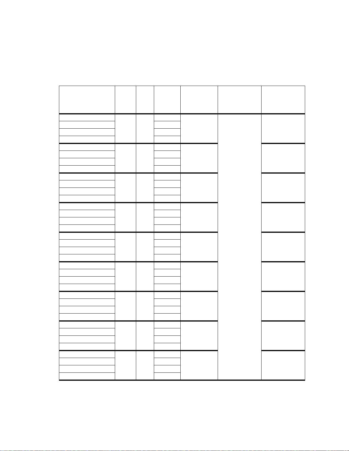
Models
6.0 Inch Motor
* Optimal seal life is achieved at less than 80 cycles per minute.
Part No. Model Ratio Seal
Material
Maximum
Working
Pressure
psi (MPa, bar)
Maximum
Pneumatic Inlet
Pressure
psi (MPa, bar)
Displacement /
Stroke*
in3(ml)
T6058-576-NBR-00
T6058 576:1
NBR 58,000
(399.8, 3998)
100 (0.69, 6.9)
0.12 (2.0)
T6058-576-FKM-00 FKM
T6058-576-FFKM-00 FFKM
T6058-576-EPR-00 EPR
T6036-365-NBR-00
T6036 365:1
NBR 36,500
(251.6, 2516) 0.19 (3.2)
T6036-365-FKM-00 FKM
T6036-365-FFKM-00 FFKM
T6036-365-EPR-00 EPR
T6025-254-NBR-00
T6025 254:1
NBR 25,250
(174.0, 1740) 0.28 (4.5)
T6025-254-FKM-00 FKM
T6025-254-FFKM-00 FFKM
T6025-254-EPR-00 EPR
T6016-163-NBR-00
T6016 163:1
NBR 16,250
(112.0, 1120) 0.43 (7.1)
T6016-163-FKM-00 FKM
T6016-163-FFKM-00 FFKM
T6016-163-EPR-00 EPR
T6012-125-NBR-00
T6012 125:1
NBR 12,500
(86.2, 862) 0.56 (9.2)
T6012-125-FKM-00 FKM
T6012-125-FFKM-00 FFKM
T6012-125-EPR-00 EPR
T6010-101-NBR-00
T6010 101:1
NBR 10,000
(68.9, 689) 0.70 (11.5)
T6010-101-FKM-00 FKM
T6010-101-FFKM-00 FFKM
T6010-101-EPR-00 EPR
T6006-064-NBR-00
T6006 64:1
NBR 6300
(43.4, 434) 1.11 (18.1)
T6006-064-FKM-00 FKM
T6006-064-FFKM-00 FFKM
T6006-064-EPR-00 EPR
T6005-047-NBR-00
T6005 47:1
NBR 4800
(33.1, 331) 1.49 (24.4
T6005-047-FKM-00 FKM
T6005-047-FFKM-00 FFKM
T6005-047-EPR-00 EPR
T6003-032-NBR-00
T6003 32:1
NBR 3200
(22.1, 221) 2.20 (36.0)
T6003-032-FKM-00 FKM
T6003-032-FFKM-00 FFKM
T6003-032-EPR-00 EPR

Models
43A6823A
7.5 Inch Motor
* Optimal seal life is achieved at less than 80 cycles per minute.
Part No. Model Ratio Seal
Material
Maximum
Working
Pressure
psi (MPa, bar)
Maximum
Pneumatic Inlet
Pressure
psi (MPa, bar)
Displacement /
Stroke*
in3(ml)
T7568-900-NBR-00
T7568 900:1
NBR 68,000
(468.8, 4688) 75 (0.52, 5.2) 0.12 (2.0)
T7568-900-FKM-00 FKM
T7568-900-FFKM-00 FFKM
T7568-900-EPR-00 EPR
T7557-571-NBR-00
T7557 571:1
NBR 57,100
(393.6, 3936)
100 (0.69, 6.9)
0.19 (3.2)
T7557-571-FKM-00 FKM
T7557-571-FFKM-00 FFKM
T7557-571-EPR-00 EPR
T7539-397-NBR-00
T7539 397:1
NBR 39,500
(272.3, 2723) 0.28 (4.5)
T7539-397-FKM-00 FKM
T7539-397-FFKM-00 FFKM
T7539-397-EPR-00 EPR
T7525-255-NBR-00
T7525 255:1
NBR 25,500
(175.8, 1758) 0.43 (7.1)
T7525-255-FKM-00 FKM
T7525-255-FFKM-00 FFKM
T7525-255-EPR-00 EPR
T7519-195-NBR-00
T7519 195:1
NBR 19,500
(134.4, 1344) 0.56 (9.2)
T7519-195-FKM-00 FKM
T7519-195-FFKM-00 FFKM
T7519-195-EPR-00 EPR
T7516-158-NBR-00
T7516 158:1
NBR 15,750
(108.5, 1085) 0.70 (11.5)
T7516-158-FKM-00 FKM
T7516-158-FFKM-00 FFKM
T7516-158-EPR-00 EPR
T7510-100-NBR-00
T7510 100:1
NBR 10,000
(68.9, 689) 1.11 (18.1)
T7510-100-FKM-00 FKM
T7510-100-FFKM-00 FFKM
T7510-100-EPR-00 EPR
T7507-074-NBR-00
T7507 74:1
NBR 7400
(51.0, 510) 1.49 (24.4
T7507-074-FKM-00 FKM
T7507-074-FFKM-00 FFKM
T7507-074-EPR-00 EPR
T7505-050-NBR-00
T7505 50:1
NBR 5000
(34.4, 344) 2.20 (36.0)
T7505-050-FKM-00 FKM
T7505-050-FFKM-00 FFKM
T7505-050-EPR-00 EPR

Warnings
3A6823A 5
Warnings
The following warnings are for the setup, use, grounding, maintenance, and repair of this equipment. The exclama-
tion point symbol alerts you to a general warning and the hazard symbols refer to procedure-specific risks. When
these symbols appear in the body of this manual or on warning labels, refer back to these Warnings. Product-specific
hazard symbols and warnings not covered in this section may appear throughout the body of this manual where
applicable.
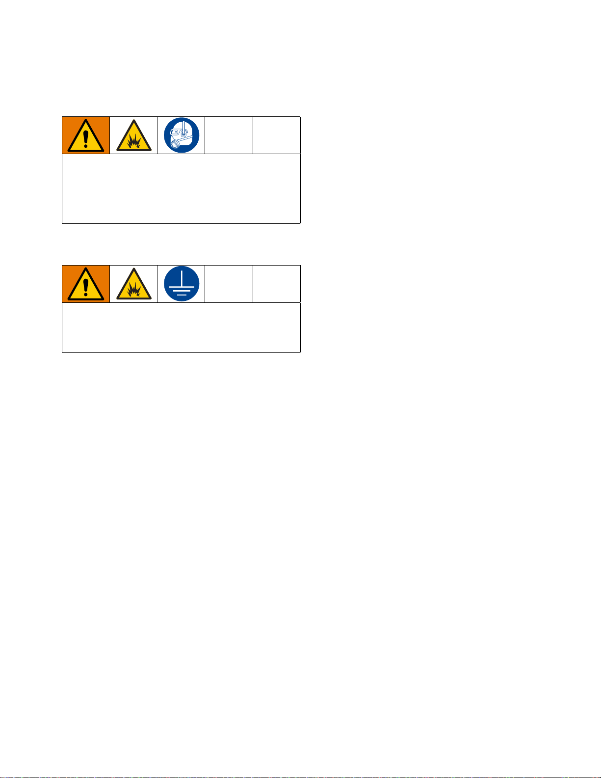
FIRE AND EXPLOSION HAZARD
When flammable fluids are present in the work area be aware that flammable fumes can ignite or
explode. To help prevent fire and explosion:
• Use equipment only in well ventilated area.
• Eliminate all ignition sources, such as cigarettes and portable electric lamps.
• Ground all equipment in the work area.
• Keep work area free of debris, including rags and spilled or open containers of solvent.
• Do not plug or unplug power cords or turn lights on or off when flammable fumes are present.
• Use only grounded hoses.
•Stopoperationimmediatelyifstaticsparkingoccurs oryou feel ashock.Do not use equipmentuntil
you identify and correct the problem.
• Keep a working fire extinguisher in the work area.
SKIN INJECTION HAZARD
High-pressure fluid from dispensing device, hose leaks, or ruptured components will pierce skin. This
may look like just a cut, but it is a serious injury that can result in amputation. Get immediate surgical
treatment.
• Do not put your hand over the fluid outlet.
• Do not stop or deflect leaks with your hand, body, glove, or rag.
• Follow the Pressure Relief Procedure when you stop dispensing and before cleaning, checking, or
servicing equipment.
• Tighten all fluid connections before operating the equipment.
• Check hoses and couplings daily. Replace worn or damaged parts immediately.
TOXIC FLUID OR FUMES HAZARD
Toxic fluids or fumes can cause serious injury or death if splashed in the eyes or on skin, inhaled, or
swallowed.
• Read Safety Data Sheet (SDS) to know the specific hazards of the fluids you are using.
• Store hazardous fluid in approved containers, and dispose of it according to applicable guidelines.

Warnings
63A6823A
EQUIPMENT MISUSE HAZARD
Misuse can cause death or serious injury.
• Do not operate the unit when fatigued or under the influence of drugs or alcohol.
• Do not exceed the maximum working pressure or temperature rating of the lowest rated system com-
ponent. See Technical Data in all equipment manuals.
• Use fluids and solvents that are compatible with equipment wetted parts. See Technical Data in all
equipment manuals. Read fluid and solvent manufacturer’s warnings. For complete information
about your material, request Safety Data Sheet (SDS) from distributor or retailer.
• Turn off all equipment and follow the Pressure Relief Procedure when equipment is not in use.
• Checkequipmentregularly.Repairorreplacewornordamagedparts immediately with genuineman-
ufacturer’s replacement parts only.
• Do not alter or modify equipment. Alterations ormodifications may void agency approvals and create
safety hazards.
• Make sure all equipment is rated and approved for the environment in which you are using it.
• Use equipment only for its intended purpose. Call your distributor for information.
• Route hoses and cables away from traffic areas, sharp edges, moving parts, and hot surfaces.
• Do not kink or over bend hoses or use hoses to pull equipment.
• Keep children and animals away from work area.
• Comply with all applicable safety regulations.
PERSONAL PROTECTIVE EQUIPMENT
Wear appropriate protective equipment when in the work area to help prevent serious injury, including
eye injury, hearing loss, inhalation of toxic fumes, and burns. Protective equipment includes but is not
limited to:
• Protective eyewear, and hearing protection.
• Respirators, protective clothing, and gloves as recommended by the fluid and solvent manufacturer.
Installation
3A6823A 7
Installation
Grounding
Pump: ground through electrically conductive pneu-
matic and fluid lines.
Pneumatic and fluid lines: use only electrically con-
ductive lines.
Air compressor: follow manufacturer’s recommenda-
tions.
Fluid supply container: follow local code.
Required Accessories
Install the following required accessories in the order
shown in FIG. 1, using adapters as necessary.
NOTE: If you supply your own accessories, be sure they
are adequately sized and pressure rated for your sys-
tem.
Pneumatic Line
•Bleed-type master pneumatic valve (C): required
in your system to relieve air trapped between it and
the pneumatic motor when the valve is closed.
• Be sure the valve is easily accessible from the
pump and located downstream from the pneu-
matic regulator.
•Pump pneumatic regulator (D): to control pump
speed and outlet pressure. Locate it close to the
pump.
•Pneumatic line filter (B): removes harmful dirt and
moisture from compressed air supply.
Fluid Line
•Fluid filter/strainer (F): with a 60 mesh (250
micron) stainless steel element to filter particles
from the fluid before it reaches the pump.
•Supply fluid shutoff valve (N): shuts off supply
fluid flow.
•Shutoff/bleed valve (G): shuts off pump fluid flow
to hydraulic system.
•Fluid pressure relief valve (H): use to release
pressure in outlet lines by redirecting fluid to the
fluid supply container.
Flush Before Using Equipment
The equipment was tested with lightweight oil, which is
left in the fluid passages to protect parts. To avoid con-
taminating your fluid with oil, flush the equipment with a
compatible solvent before using the equipment. See
Flush the Equipment, page 10.
To reduce the risk of injury from ejected ice, do not
operate the motor without a plumbed exhaust line or
muffler installed.
Installation must comply with all local codes and regu-
lations.
The equipment must be grounded to reduce the risk
of static sparking. Static sparking can cause fumes to
ignite or explode. Grounding provides an escape wire
for the electric current.

Installation
83A6823A
Typical Installation
FIG. 1 is an example of an installation with an Intensifier
pump. Your installation may differ from what is shown
here. (See Required Accessories, page 7.) The Inten-
sifier pump (E) is the only component in FIG. 1 supplied
by HiP. All other components are available from HiP to
be ordered separately.
Key:
A Main pneumatic supply line
B Pneumatic line filter
C Bleed-type master pneumatic valve
D Pump pneumatic regulator
E Intensifier pump
F Fluid filter/strainer (at the fluid supply container)
G Shutoff/bleed valve (outlet only)
H Fluid pressure relief valve
J Fluid inlet line
K Inlet port
LOutletport
M Fluid outlet line to hydraulic system
N Supply fluid shutoff valve
FIG. 1: Typical Installation
A
B
D
C
E
H
J
G
F
KL
M
Fluid Supply
Container
N

Installation
3A6823A 9
Mount the Pump and Connect
Fluid Supply
NOTE: A strainer (F) or fluid filter is required before the
pump inlet. This will keep debris from the fluid supply
container from reaching the pump and check valve
seals. For maximum performance, the inlet port (K)
should be mounted below the fluid supply container.
1. Mount the pump (E) and connect the fluid inlet
line (J).
Connect Pneumatic Supply
1. Install the pressure regulator (D) and gauge to con-
trol the inlet pressure. See Models on page 3 for
your model’s maximum pneumatic pressure.
2. Install a pneumatic line filter (B) to keep debris from
affecting pump performance and to increase pump
life.
3. Connect the outlet of the master valve (C) to the 1/2
in. female NPT port on the Intensifier pump (E).
Connect Fluid Outlet
1. Connect a fluid line from the outlet port (L) to the
hydraulic system.
2. Install a fluid pressure relief valve (H) on the outlet
side of the pump.
Operation
10 3A6823A
Operation
Pressure Relief Procedure
Perform the Pressure Relief Procedure when-
ever you see this symbol.
NOTE: Always discharge fluid into an approved con-
tainer or location.
1. Close the bleed-type master pneumatic valve (C).
2. Use the fluid pressure relief valve (H) to release
pressure in system by redirecting the fluid to the
fluid supply container.
3. Set the pressure regulator (D) to 0 PSI/MPa/bar.
Flush the Equipment
• Flush with a fluid that is compatible with the fluid
being dispensed and the equipment wetted parts.
1. Perform the Pressure Relief Procedure.
2. Connect inlet to the supply source of the flushing
fluid.
3. Connect outlet to a waste reservoir.
4. Run the pump until the dispensed fluid is predomi-
nately flushing fluid.
5. Perform the Pressure Relief Procedure.
This equipment stays pressurized until pressure is
manually relieved. To help prevent serious injury from
pressurized fluid, such as skin injection and splashing
fluid, follow the Pressure Relief Procedure when
you stop dispensing and before cleaning, checking, or
servicing the equipment.
To avoid fire andexplosion, always ground equipment
and waste container. To avoid static sparking and
injury from splashing, always flush at the lowest pos-
sible pressure.

Operation
3A6823A 11
Prime the Pump
1. Perform the Pressure Relief Procedure on
page 10.
2. Attach the hydraulic system to the fluid outlet line
(M) and verify all connections and fluid lines are
tight.
a. Close the shutoff/bleed valve (G) and open the
fluid pressure relief valve (H).
b. Set the pressure regulator (D) to
0 PSI/MPa/bar.
NOTE: The pressure regulator (D) and bleed-type mas-
ter pneumatic valve (C) both affect the pump cycle rate.
After the inlet pressure is set, the bleed-type master
pneumatic valve (C) can serve as a speed control.
3. Turn on the air at the bleed-type master pneumatic
valve (C). Slowly increase the pressure using the
pressure regulator (D) to slowly cycle (less than 80
cycles per minute) the Intensifier pump (E).
4. Keep the pump cycle rate at less than 80 cycles per
minute. The pump is primed when discharge from
the pump has transitioned from air, to bubbly fluid,
to pure fluid.
Build Pressure
1. Close the fluid pressure relief valve (H) and open
the fluid outlet valve (G) that is connected to the
hydraulic system. Bleed the hydraulic system of all
air per the manufacturer’s recommended practice.
2. Turn off the air at the pneumatic valve (C) and set
the pressure regulator (D) to 0 PSI/MPa/bar. Seal
the hydraulic system per the manufacturer’s recom-
mended practice. You are now ready to build pres-
sure.
3. Turn on the air at the bleed-type master pneumatic
valve (C) and slowly increase pressure with the
pressure regulator (D) until the desired pressure is
produced in the hydraulic system.
NOTE: Hydraulic pressure increases proportionally to
inlet pressure up to the maximum working pressure of
the pump.
4. After pressurization of the hydraulic system is com-
plete, perform the Pressure Relief Procedure on
page 10.
NOTICE
Pump runaway may occur if the pressure regulator is
opened too far for pressure settings, causing damage
to the packing seals.

Maintenance
12 3A6823A
Maintenance
Preventive Maintenance
Schedule
The operating conditions of your particular pump deter-
mines how often maintenance is required. Establish a
preventive maintenance schedule by recording when
and what kind of maintenance is needed, and then
determine a regular schedule for checking your pump.
Tighten Threaded Connections
Check that all threaded connections are tight before
each use and at routine intervals.
Storage
If the pump is going to be stored for long periods, flush
the pump with a light-weight oil or rust inhibitor before
storage to protect pump components. Store the pump
with protective fluid inside whenever possible.
Troubleshooting
3A6823A 13
Troubleshooting 1. Perform Pressure Relief Procedure, page 10,
before checking or repairing pump.
2. Check all possible problems and causes before dis-
assembling pump.
Problem Cause Solution
Air bubbles in fluid. Fluid inlet line is loose. Tighten.
Fluid leaking. Loose fittings. Tighten fittings.
Worn seals. Replace packing.
Pump stroking, but no fluid moving. Air in pump. Prime pump. See page 11.
Worn or damaged check valve seals. Rebuild check valves.
Pneumatic motor will not run. Damaged pneumatic valve (217). Replace or service pneumatic valve (217).
See page 17.
Damaged pilot valve (219). Replace pilot valves (219).
See page 19.
Fluid valve (K) shut. Open fluid valve (K).
See page 8.
Air continuously exhausting around
pneumatic motor plunger. Damaged u-cups (203 and 233). Replace plunger u-cups (203 and 233).
See page 20.
Air continuously exhausting from muffler. Damaged pneumatic valve plate (305) or
cup (312). Replace or service pneumatic valve (217).
See page 17.
Pneumatic motor “bounces” at top of
stroke. Damaged bottom pilot valve (219). Replace bottom pilot valve (219). See
page 19.
Pneumatic motor “bounces” at bottom of
stroke. Damaged top pilot valve (219). Replace top pilot valve (219).
See page 19.
Icing inside motor. Pneumatic motor operating at high pres-
sure or high cycle rate. Reduce pressure, cycle rate, or duty cycle
of motor.
Excessive moisture in pneumatic supply
line. Reduce dew point of compressed air in
moisture coalescing filter.
Pump fails to operate. Restricted line or inadequate air supply;
closed or clogged valves. Clear line or increase air supply. Check
that the valves are open.
Obstructed fluid line; fluid line ID is too
small. Open, clear*; use line with larger ID.
Pump operates, but output is low. Worn packings in pump. Replace packings. See page 15.
Held open or worn check valves or pack-
ings. Clear valve; replace packings.
See page 15.
Erratic or accelerated pump speed. Exhausted fluid supply. Refill and prime.
Held open or worn check valves or
packings. Clear valve, replace packings.
See page 15.
Fluid being pumped is visible on the pack-
ing nut. Worn packings. Replace packings. See page 15.
Repair - Pump Lower
14 3A6823A
Repair - Pump Lower
• Always use Genuine Graco Parts and Accessories,
available from your Graco distributor.
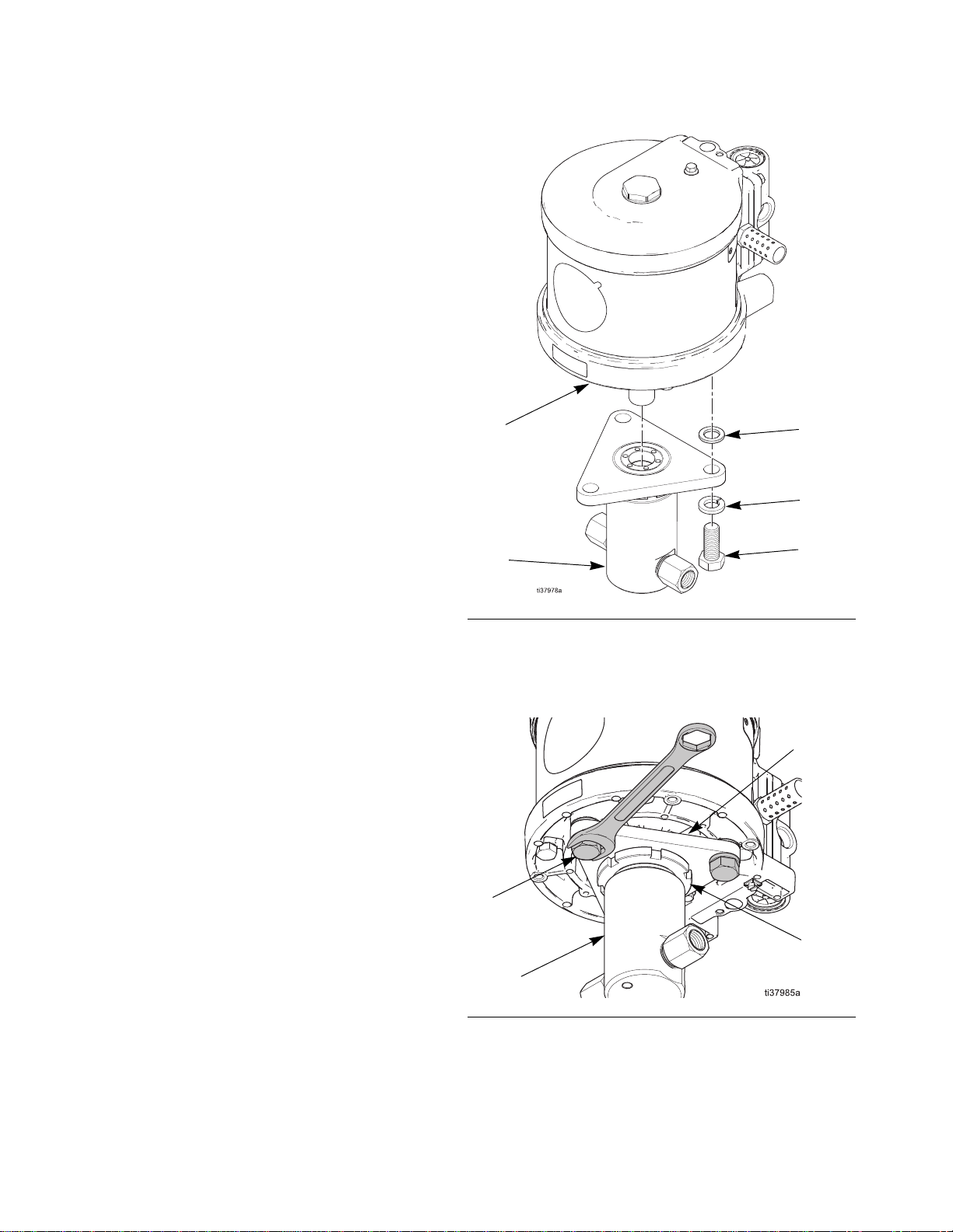
Disconnect the Pump Lower
1. Stop the pump.
2. Perform the Pressure Relief Procedure, page 10.
3. Disconnect the fluid lines.
4. Remove the screws (5) and remove the pump
lower (3). It is not necessary to loosen or remove
either the lower bracket (111) or the locking ring
(110) from the pump lower (3).
5. Slide the pump lower (3) off of the pump, with the
lower bracket (111) and locking ring (110) still
attached to the pump lower.
Before servicing or repairing your pump, verify that
pressure is relieved according to the Pressure Relief
Procedure, page 10, and that all fluid and pneumatic
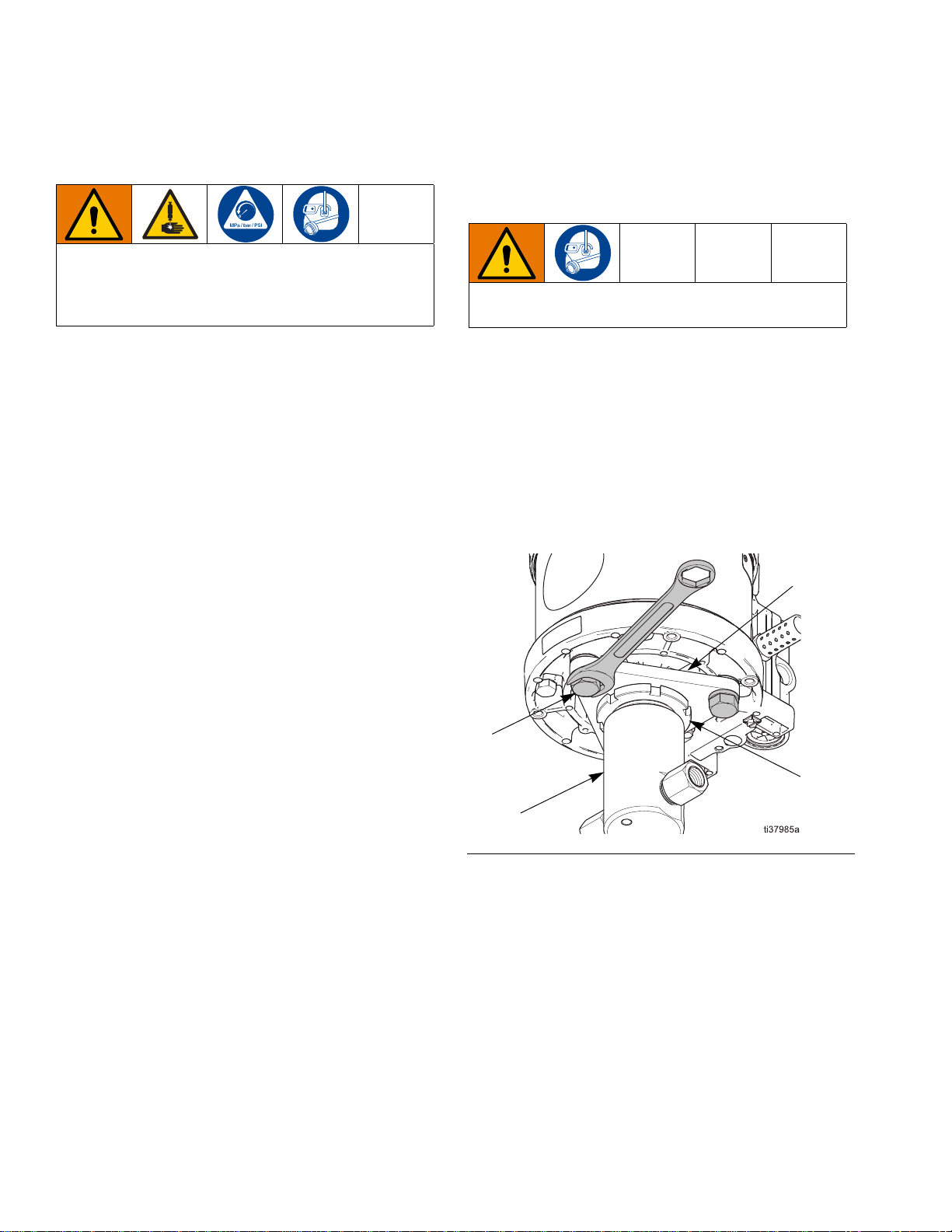
lines are properly shut off. Threads are very sharp. Use a rag to protect hands
when turning or carrying the pump.
FIG. 2
111
5
3
110
Repair - Pump Lower
3A6823A 15
Pump Repair
1. Remove the packing nut (109) from the top of the
fluid cylinder (101). Do not remove either the lower
bracket (111) or locking ring (110).
2. Remove the seal stack. Inspect seals and rings for
damage and wear, and replace as necessary
3. Remove the inlet and outlet check housings (117
and 118; low- and medium-pressure pumps) or inlet
and outlet checks (122 and 123; high-pressure
pumps).
4. Medium-pressure pumps only. Remove the
o-rings (115), compression springs (116), and check
poppets (114).
5. Low-pressure pumps only. Remove the o-rings
(113 and 115), compression springs (116), and
check poppets (114). Inspect for damage and wear,
and replace as necessary.
NOTE: Assuming the orientation shown in FIG. 3, and
with the point of lower bracket (111) pointing to the front
of the pump when installed, the inlet port will be to the
left and the outlet port to the right.
6. Low- and medium-pressure pumps only. Install
the small o-ring (115) onto the check poppet (114),
then install the poppet (115) and compression
spring (116) into the inlet check housing (117), as
shown.
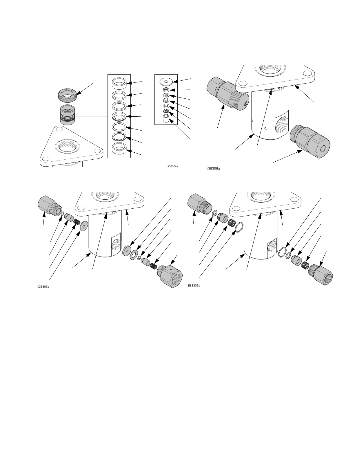
FIG. 3
Seal Stacks High Pressure Checks
Low Pressure Checks
Low/Medium Pressure High Pressure
102
107
106
105
104
103
102
108
107
106
105
104
103
102
109
122
123
111
110
117
115
114
116
113
113
115
114
116
118
110
111
101
101
Medium Pressure Checks
110
111
117
115
116
121
114
119
120
114
116
115
118
101
Repair - Pump Lower
16 3A6823A
7. Low-pressure pumps only. Install the large
o-ring (113) into the inlet port of the fluid
cylinder (101), then install the inlet check
housing (117).
8. Medium-pressure pumps only. Install the spacer
(121) into the inlet port of the fluid cylinder (101),
then install the inlet check housing (117).
9. Low- and medium-pressure pumps only. Install
the small o-ring (115) onto the check poppet (114),
then install the poppet (114) and compression
spring (116) into the outlet check housing (118), as
shown.
10. Low-pressure pumps only. Install the large
o-ring (113) into the outlet port of the fluid
cylinder (101), then install the outlet check housing
(118).
11. Medium-pressure pumps only. Install the spacers
(119 and 121) into the outlet port of the fluid cylinder
(101), then install the outlet check housing (118).
12. Stack and install the seal stack, as shown. Use
grease during installation.
13. Install the packing nut (109) with a medium strength
thread locking compound, and torque to 5-10 ft-lbs
(7-14 n•m). The packing nut (109) should be flush
with the surface of the fluid cylinder (101).
Reconnect the Pump Lower
1. Align the pump lower (3) so that the inlet port is to
the left when facing the front of the pump (1).
2. Install the screws (5), lock washers (4), and spacers
(2), as shown in FIG. 4, and align with the holes in
the bottom of the pump (1), as shown in FIG. 5.
3. Torque the screws (5) to 50-60 ft-lbs (68-81 N•m).
FIG. 4
FIG. 5
1
35
4
2
111
5
3
110
Repair - Pneumatic Motor
3A6823A 17
Repair - Pneumatic Motor
Pneumatic Valve
Replace Complete Pneumatic Valve
1. Stop the pump and perform the Pressure Relief
Procedure, page 10.
2. Disconnect the pneumatic line to the motor.
3. See the figure on page 26. Use a 10 mm socket
wrench to remove four screws (218). Remove the
pneumatic valve (217) and gasket (216*).
4. To repair the pneumatic valve, go to Disassemble
the Pneumatic Valve, page 17. To install a replace-
ment pneumatic valve (217), continue with step 5.
5. Align the new pneumatic valve gasket (216*) on
the manifold, then attach the pneumatic valve (217).
Torque screws (218) to 95-105 in-lb (11-12 N•m).
6. Reconnect the pneumatic line to the motor.
Replace Seals or Rebuild Pneumatic Valve
Inspect and replace seals and worn parts while disas-
sembling and reassembling the pneumatic valve on the
following pages.
Use FIG. 6 and the following table to identify the kits
needed for replacements:
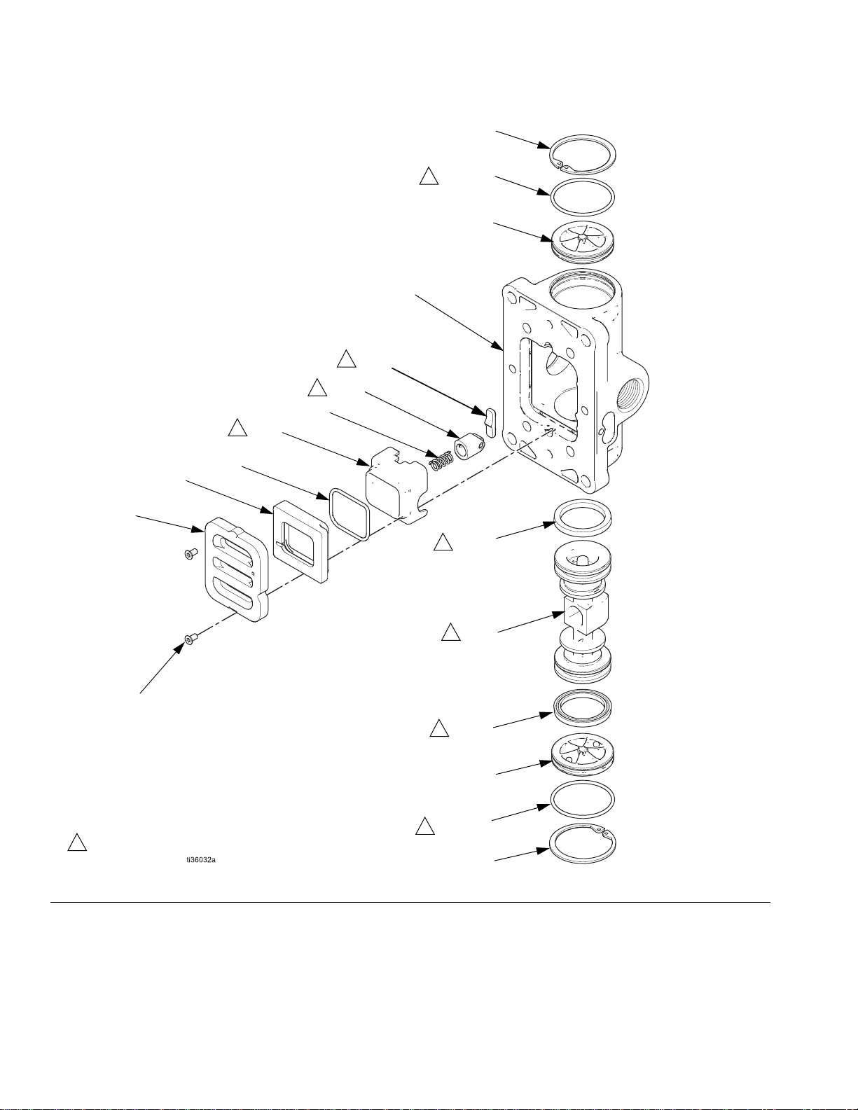
Disassemble the Pneumatic Valve
1. Perform steps 1-3 under Replace Complete Pneu-
matic Valve, page 17.
2. See FIG. 6. Use a T10 star screwdriver to remove
two screws (309†). Remove the valve plate
(305), cup (312), and spring (311).
3. See FIG. 6. Remove the snap ring (310) from
each end. Use the piston (302) to push the end
caps (307) out of the ends. Remove end cap
o-rings (306†).
4. Remove the piston (302). Remove the u-cup seals
(308†) from each end, and the detent assembly
(303) and detent cam (304) from the center.
Symbol Kit Description
† Pneumatic Valve Seal Kits. See page 29.
Pneumatic Valve Repair Kits. See page 29.
Pneumatic Valve End Cap Kits. See
page 29.
Repair - Pneumatic Motor
18 3A6823A
FIG. 6
310
307
307
†309
305
312 311
303
302
†308
†
308
301
304
310 ti16213a
†321
†321
313
314
1
1
1
1
1
1
1
1
1
Apply lubricant.
Repair - Pneumatic Motor
3A6823A 19
Reassemble the Pneumatic Valve
1. See FIG. 6. Lubricate detent cam (304) and install
into housing (301).
2. See FIG. 7. Lubricate the u-cups (308†) and install
on the piston (302) with lips facing toward the cen-
ter of the piston.
3. See FIG. 6. Lubricate both ends of the piston (302)
and install it in the housing (301).
4. Lubricate and install the detent assembly (303)
into the piston (302).
5. Lubricate new o-rings (306†) and install on the
end caps (307). Install the end caps into the hous-
ing (301).
6. Install a snap ring (310) on each end to hold end
caps in place.
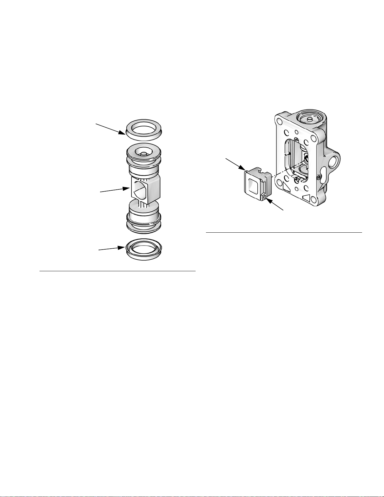
7. Install the spring (311). Lubricate and install the
pneumatic valve cup (312), see FIG. 8. Align the
small round magnet with the pneumatic inlet.
8. Install the valve plate (305). Tighten the screws
(309†) to hold it in place.
9. Perform steps 5 and 6 under Replace Complete
Pneumatic Valve, page 17.
Replace Pilot Valves
1. Stop the pump and perform the Pressure Relief
Procedure, page 10.
2. Disconnect the pneumatic line to the motor.
3. Use a 10 mm socket wrench to remove the old pilot
valves (219) from the top (213) and bottom (201)
covers. See the figure on page 26.
4. Lubricate and install the new pilot valves (219).
Torque to 95-105 in-lb (11-12 N•m).
5. Reconnect the pneumatic line to the motor.
FIG. 7
Lips face down
Lips face up
†308
†308
302
ti12754a
FIG. 8
312
ti16283a
Magnet

Repair - Pneumatic Motor
20 3A6823A
Repair Pneumatic Motor
NOTE: Pneumatic Motor Seal Kits are available. See
Pneumatic Motor Parts List, page 27, for the correct
kit for your motor. For best results, use all parts in the
kit.
Disassemble the Pneumatic Motor
1. Disconnect the Pump Lower, page 14.
2. Use a 10 mm socket wrench to remove the four
screws (218), and remove the pneumatic valve
(217) and gasket (216). See the figure on page 26.
3. Remove the four screws (218), and remove the
manifold (215) and two gaskets (214).
4. Use a 10 mm socket wrench to remove the pilot
valves (219), and the top and bottom covers (213
and 201).
5. Use a 17 mm socket wrench to the tie bolts (210).
The number of bolts depends on your configuration.
6. Remove the top cover (213) and the o-ring (209).
7. Remove the shield (212) from around the
cylinder (211), and remove the cylinder.
8. Slide the piston assembly straight up off the bottom
cover (201).
NOTE: There is no need to take apart the piston assem-
bly. If any part is worn or damaged, the individual pis-
tons and plungers are available as kits and should be
replaced.
9. Remove the o-ring (208) from around the piston
(205).
10. Remove the retaining ring (204), u-cup seals (203
and 233), and the o-ring (209) from the bottom
cover (201).
Reassemble the Pneumatic Motor
NOTE: For easier reassembly, start with the top
cover (213) turned over on the workbench and assem-
ble the pneumatic motor upside-down.
1. Lubricate and install the o-ring (209) on the top
cover (213). See the figure on page 26.
2. Install the upper bumper (229) on the top cover.
3. Lubricate the inside of the cylinder (211). Lower the
cylinder onto the top cover (213).
4. Lubricate and install the o-ring (208) around the pis-
ton (205).
5. Slide the piston assembly down onto the
cylinder (211). Be sure the o-ring (208) stays in
place.
6. Install the shield (212) around the cylinder (211) and
in the groove on the top cover (213).
7. High-pressure pumps only. Lubricate and install
the u-cups (203 and 233) into the seal
housing (240).
8. The arrange the seal stack as shown in FIG. 9. (low-
and high-pressure pumps have different seal stack
arrangements), then lubricate and install into the
bottom cover (201).
9. Install the spacer (202) and retaining ring (204).
Configuration
T6000
T7500
ti12749a
ti12750a
This manual suits for next models
92
Table of contents


 instruction manual")


