HI-PRESS TANGYE HYDRAMITE Quick guide

Operating & Safety
Instructions

Operating & Safety Instructions
Please read this instruction booklet carefully before operating the product and keep in a safe
place for future reference.
It is the responsibility of the purchaser to ensure that operators are properly trained in the safe
use of this equipment and have access to Tangye Operating and Safety Instruction s.
No modication and/or additions may be made to this equipment without the written
permission of the manufacturer.
It is expected that the product is used by competent technical personnel who have been
properly trained to use hydraulic lifting equipment
Hydramite & Hydralite
Description
This equipment is provided for the purpose of lifting or lowering loads, or exerting a force,
under the control of a trained operator.
The equipment is supplied completely assembled and ready for use. No service adjustments are
necessary or possible duri ng operation.
An internal safety relief valve (factory set) is tted which limits the load that may be lifted to the
equipment rated load + 10% maximum.
Before Each Use
Ensure that the jack is in good condition.
Check the external surfaces for absence of mechanical damage and/or oil leaks. If either is
present do not use the equipment and have it serviced.
Ensure that the external surfaces are dirt free.
Check the oil level.
Operating Instructions
Place the jack on a rm level foundation fu lly supporting the jack base, and if necessary place
suitable material between the load point and jack ram to avoid damaging the structure to be
lifted.
Use the jack by operating the lever in a steady controlled movement at a maximum of 30 strokes
per minute.
Remove the operating lever when not in use.

The ram should only be extended hydraulically; it should never be pulled out by hand or used to
carry the jack.
Do Not position the jack by using the operating lever in the release valve. If the jack is t o be
placed some distance under the load, use the operating lever in the operating lever/quadrant
socket to position the jack.
Do Not drop loads onto the jack. If the jack is inadvertently subjected to a shock load, remove
from service and have it checked by a competent examiner or service agent.
Do Not overload the jack especially when lowering loads.
Do Not under any circumstances go under a load when hydraulic jacks solely support it.
If using more than one jack, all the jacks must be able to individually raise the load e.g. two
PS620 jacks cannot be used to lift a 30T load as it impossible to pump both jacks at exactly the
same rate, or lower the jacks at exactly the same rate, one of the jacks will end up with an excess
load and is liable to fail. In such case two PS630 jacks should be used to raise a load of 30T.
Operating Environments
The jack is intended for use in industrial environments, inside or outside, between
temperatures of –20 to +50°C. Outside these limits, or in explosive atm ospheres/areas of
nuclear radiation, consult the manufacturer before use.
Noise and Vibration
By its design, the jack operates slowly under manual effort. There is no noticeable noise or
vibration.
HYDRAMITE
Fig. 1
Function (read in conjunction with Fig. 1)
The permissible working load and the travel of the hydraulic jack are marked on the equipment.
The jack (1) has an in -built hydraulic pump, which is worked by means of an operating lever (2),
under the control of the o perator. The jack ram (3) is raised on each downward stroke of the
lever. For lifting, the lever is placed fully into the operating socket (4).
For lowering, the lever is removed from the socket and placed into the release screw (5).
Turning this anti -clockwise will allow the ram to descend. The amount this is rotated will
control the speed of descent; only open a very small amount (approx. 5°) at rst.
Close the release valve after use, to ready the jack for the next operation.
Operating Positions
The hydraulic system is sealed – the jack may be used in any mounting position.
Oil Level Check
Lay the jack on its side with the ller plug uppermost and remove the ller plug. There should
be no airspace under the plug.
If oil needs to be added ens ure that the surrounding area is clean and ll to the bottom of the
plug threads. Use high quality hydraulic oil such as Shell Tellus ISO 32 or equivalent.

HYDRALITE
Fig.2
Function (read in conjunction with Fig. 2)
The permissible working load and the travel of the hydraulic jack is marked on the equipment,
also see table 1.
The jack has an in -built hydraulic pump, which is worked by means of an operating lever ( 1),
under the control of the operator. The jack ram ( 2) is raised on each downward stroke of the
lever. For lifting, the operating lever (1) is placed fully into the operating quadrant ( 3).
Three positions are provided to enable the operator to choose the best ergonomic position. For
lowering, the lever is removed from the quadrant and placed into the release screw ( 4). Turning
this anti -clockwise will allow the ram to descend. The amount this is rotated will control the
speed of descent; only open a very small amount (approx. 5°) at rst.
Close the release valve, to ready the jack for the next operation.
After use store the jack in an upright position with the ram fully retracted and the operating
quadrant in the ‘up’ position.
Table 1
Model Capacity (ton ne) Stroke (ins) Claw Capacity (ton ne)
PS620
20
6
8
PS1220 20 12 8
PS630 30 6 12
PS1230
30
12
12
PS660 60 6 24
PS1260
60
12
24
P6100 100 6 N/A
Add: Sfor Screwed Ram (for example PS620S)
Cfor Claw (for example PS620C)

Jacks with Screwed Rams (Type S)
All models can be provided with screwed rams and locking collars. The purpose for this is to
mechanically support a load at a required position without relying on the hydraulic circuit.
When the load is at the required position, rotate the locking collar clockwise until it rests hand -
tight on the top of the jack body.
To undo – operate the jack so that the hydraulic circuit just takes the load off the locking collar.
Rotate the collar anti -clockwise until it reaches the top of the ram.
Safety Note : Lifting claws must never be used with screwed ram jacks.
Jacks with Lifting Claws (Type C)
These claws are supplied as an accessory to provide a low height lifting point. When tted,
lifting must always, and only, be carried out on the toe of the claw.
The capacity of the claw is 40% of the capacity of the jack to which it is tted (See table 1), if the
claw is overloaded it could snap and put the operator in danger. Jacks intended for use with
claws have extended bases which prevent the jack from toppling over when a load is applied to
the claw. Never attempt to use a claw on a jack without an extended base. They must only be
used for vertical movements of loads.
The recess in the head of the claw ts around the ram top, and the heel of the claw rests against
the front face of the jack. Ensure the claw is seated properly before use and also that the toe is as
far under the load as possible.

100 Tonne Jacks Only
This jack is tted additionally with a low pressure pump intended for faster movement of the
ram under no load. i.e. to close daylight. The low pressure quadrant is on the left hand side of
the jack and operates in the same manner as the high pressure pump.
Stroke Limit
The jack is tted with an internal by -pass valve which prevents the ram stroke exceeding the
design limit. If the jack is operated in this condition, oil passes back to the reservoir. If operation
is continued, some oil may by -pass the ram scraper ring and appear on the top of the jack. Cease
operating the jack, wipe off surplus oil and check the oil lev el of the jack.
Operating Positions
The jack should only be used in the positions shown below:
Oil Level Check
Remove the dipstick (see Fig. 1) and check the oil level. The maximum level is marked on the
dipstick; the level should be within 5mm of this mark. The dipstick should be screwed fully into
position to determine the level.
If oil needs to be added ensure that the surrounding area is clean. Use high quality hydraulic oil
such as Shell Tellus ISO 32 or equivalent.

HYDRACLAW
Description
The jack is constructed from high strength ferrous materials throughout. The forged claw is
guided in the body to relieve the ram of bending loads.
Oil Level Check
The jacks are supplied lled and ready for use. However, before using the jack for the rst time,
the oil level should be checked. The oil used should be high quality hydraulic oil such as Shell
Tellus ISO32 or equivalent.
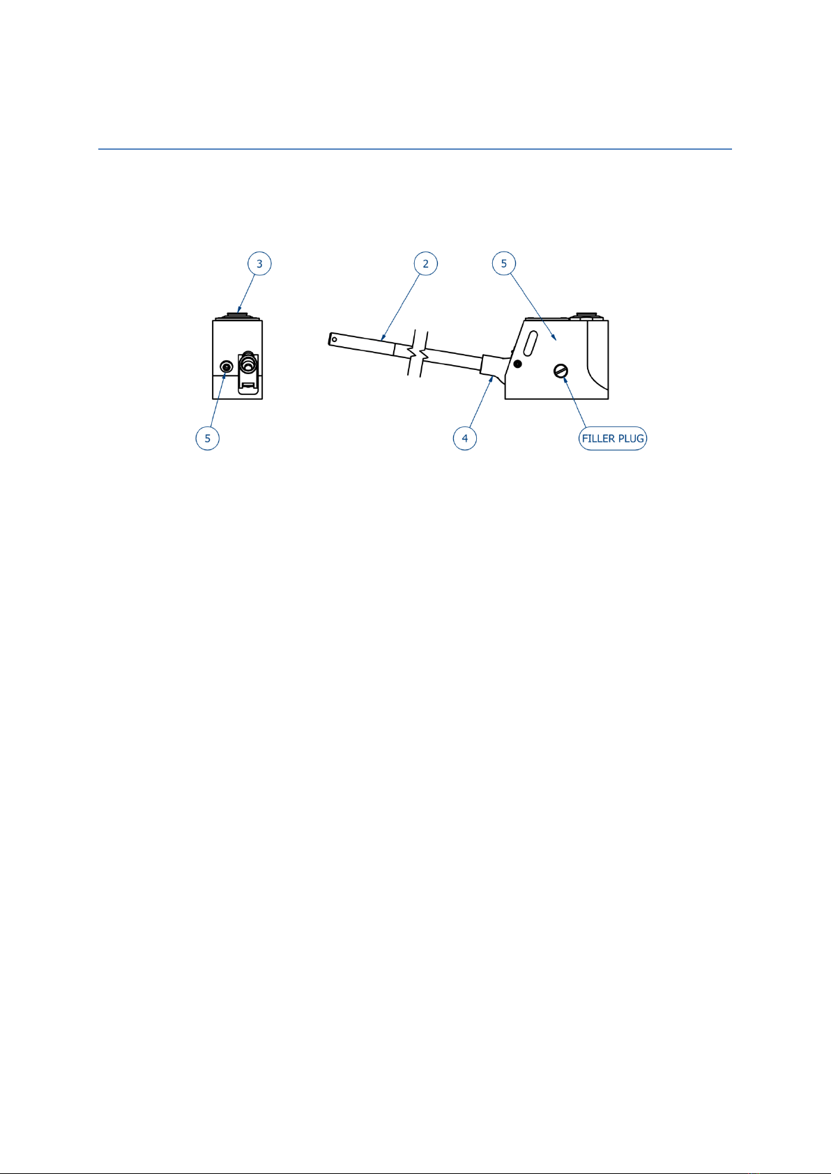
To check the oil level, stand the jack on its base in an upright position, remove the ller plug and
seal (1) and check that the oil is level with the bottom of the ller plug hole.
When relling from empty, or if air is in the circuit, the following procedure should be observed:
Ensure that the release valve (2) located inside the operating socket (3) is open. With
the jack standing on its base, ll with oil to the bottom of the ller plug hole, replace the
ller plug and seal and close the release valve screw.
Pump the ram/claw to its full extent and turn the jack upside down. Whilst in the
inverted position, open the release valve and apply pressure on the jack body to press
the ram/claw to its bottom position.
Repeat this procedure as often as necessary to remove all air from the system. Again
stand the jack on its base, remove the ller plug and check the oil is level with the
bottom of the ller plughole. If not, top up to this level, replace ller plug and seal.

Supporting the Jack
Before use always ensure the jack is fully supported on a at, rm surface with due regard to
the load to be lifted.
Position the jack so that the load bears centrally on the top of the ram or on the full extent of the
claw, ensuring that the load cannot touch any static part o f the jack during lifting.
Lifting
The release valve (2) is located inside the operating socket (3) and can be opened or closed by
engaging the end of the operating lever. Turning clockwise closes the valve; excessive force is
unnecessary and could lead to damage. With the release valve closed and the operating lever in
the socket, reciprocate the lever to operate the jack.
The ram will extend on each downward stroke of the lever. When the full extension has been
achieved a positive stop is engaged; fur ther pumping will only circulate oil within the jack. This
circulation will be apparent to the operator because increased effort is necessary to move the
operating lever.
Do not continue pumping after this has been reached.
Lowering
Place the operati ng lever in the operating socket and ensure that the end of the lever is engaged
in the release valve. Carefully turn anti -clockwise. If the jack is under load, turn only a small
amount, (approx. 5°); in the rst instance which will allow the speed of des cent to be controlled
by the further extent of the valve opening.
Maintenance
In the normal course of service, no routine maintenance should be required, but attention to the
following will assist in obtaining satisfactory service.
The oil level should be periodically checked; the reservoir should not be overlled. Always use
clean oil of the type specied.
Always wipe the claw/ram extension clean before retracting. Lightly grease the claw tenons
occasionally.
Inspect and clean ram and jack after ev ery use, if subjected to abnormal or shock loading
inspect for damage immediately.
Refer to authorised service centre for testing and service.

Safety information
Always ensure that the full base area of the jack is supported when in use.
Always ensure that loads are applied centrally to the ram or to the full extent of the claw.
Always clean the ram and retract after use.
Always remove the jack operating handle when not in use.
In operation never drop loads onto the jack. Always raise the head/ toe to the load.
Never extend the ram by any means other than by pumping the jack.
Do Not attempt to exceed the rated load of 5 tonnes on head or toe.
Do Not allow any person (s) to work under the load when it is only supported by hydraulic
jacks.
Do Not use if there is evidence of oil leakage.
HI-PRESS HYDRAULICS LTD
RIVERSIDE WORKS,
FORGE ROAD,WHALEY BRIDGE,
HIGH PEAK, SK23 7HY
T: 01663 735089 - F: 01663 735090
HI-PRESS HYDRAULICS LTD
UNIT 2, HALL HOUSE IND EST,
NEW HUTTON, KENDAL,
CUMBRIA, LA8 OAH
T: 01539 734005 - F: 01539 734006
This manual suits for next models
8
Table of contents
Popular Jack manuals by other brands


Central Hydraulics
Central Hydraulics 94143 Set up and operating instructions

HOLZMANN MASCHINEN
HOLZMANN MASCHINEN RWH 150XLIFT user manual

BGS technic
BGS technic 70042 instruction manual

Sealey
Sealey 2000LJ instructions

Chicago Pneumatic
Chicago Pneumatic CP9603 Instruction manual/safety instruction

K Tool International
K Tool International KTI-63250A owner's manual


