Hi Sharp HS-MP3200 User manual

Thank you for purchasing our product.
Please read this User’s Manual before
using the product. Change without Notice
P V M
User’sManual
Safety Precautions
CAUTION
RISK OF ELECTRICAL
SHOCK. DO NOT OPEN !
CAUTION: TO REDUCE THE RISK OF ELECTRICAL SHOCK,
DO NOT REMOVE COVER (OR BACK), NO USER
SERVICEABLE PARTS REFER SERVICING TO
QUALIFIED SERVICE PERSONNEL.
This label may appear on the bottom of the unit due to space limitations.
WARNING: TO PREVENT FIRE OR SHOCK HAZARD, DO NOT
EXPOSE UNITS NOT SPECIFICALLY DESIGNED FOR
The lightning flash with arrowhead symbol, within an equilateral triangle, is
intended to alert the user to the presence of insulated dangerous Voltage
within the product’s enclosure that may be sufficient magnitude to constitute
risk of electrical shock to persons.
The exclamation point within an equilateral triangle is intended to alert the
user to the presence of important operation and maintenance (servicing)
instructions in the literature accompanying the appliance.
Attention: installation should be performed by qualified service Personnel
only in accordance with the National Electrical Code or applicable local
codes.
Power Disconnect. Units with or without ON-OFF switches have power
supplied to the unit whenever the power cord is inserted into the power
source; however, the unit is operational only when the ON-OFF switch is
the ON position. The power cord is the main power disconnect for all
unites.
“CAUTION: Danger of explosion if battery is incorrectly replaced.
Replace only with the same or equivalent type recommended by the
manufacturer. Dispose of used batteries according to the manufacturer‘s
instruction.”
During the warranty period (one year), we will repair or replace the DVR
free of charge.
Be sure to have the model number, serial number and vendor stick on
hard disk for service representative.
Warranty
and Service
2

3
FCC Statement:
WARNING
This device complies with Part 15 FCC Rules. Operation is subject to the following two conditions: (1)
This device may not cause harmful interference. (2) This device must accept any interference
received including interference that may cause undesired operation."
* Federal Communications Commission (FCC) Statement
WARNING
This Equipment has been tested and found to comply with the limits for a Class B digital device,
pursuant to Part 15 of the FCC rules. These limits are designed to provide reasonable protection
against harmful interference in a residential installation. This equipment generates, uses and can
radiate radio frequency energy and, if not installed and used in accordance with the instructions, may
cause harmful interference to radio communications. However, there is no guarantee that interference
will not occur in a particular installation. If this equipment does cause harmful interference to radio or
television reception, which can be determined by turning the equipment off and on, the user is
encouraged to try to correct the interference by one or more of the following measures:
- Reorient or relocate the receiving antenna.
- Increase the separation between the equipment and receiver.
- Connect the equipment into an outlet on a circuit different from
that to which the receiver is connected.
- Consult the dealer or an experienced radio/TV technician for help.
* You are cautioned that changes or modifications not expressly approved by the party responsible for
compliance could void your authority to operate the equipment.

4
Contents
1. PVM I/O............................................................................................................................6
1.1 REAR PANEL...........................................................................................................................................................................................................7
1.2 REMOTE CONTROLLER ..................................................................................................................................................................................8
1.3 DISPLAY MODE .....................................................................................................................................................................................................9
1.4 DISPLAY MODE ..................................................................................................................................................................................................10
2. OSD MENU SETUP........................................................................................................11
2.1 VIDEO SETUP .................................................................................................................... 11
2.2 PC SETTING ...................................................................................................................... 12
2.3 AUDIO SETTING ................................................................................................................13
2.4 PIP SETTING .....................................................................................................................14
2.5 SYSTEM SETTING .............................................................................................................. 15
2.6 INFORMATION ....................................................................................................................16
3. CAMREA OSD MENU SETUP ......................................................................................17
3.0 MAIN MENU....................................................................................................................... 17
3.1 GENERAL MENU ................................................................................................................18
3.2 AE MENU ..........................................................................................................................19
3.3 WDR MENU .......................................................................................................................20
3.4 DAY /NIGHT MENU............................................................................................................21
3.5 AWB MENU .......................................................................................................................22
3.6 PRIVACY MENUU..................................................................................................................23
3.7 SPECIAL MENU .................................................................................................................. 24
3.8 MESSAGE MENU ................................................................................................................ 25
4. E-MAP FUNCTION SETUP.............................................................................................26
4.1 DEVICE LIST ....................................................................................................................27
4.2 ADD DEVICE ....................................................................................................................27
4.3 ADD ALL DEVICE .............................................................................................................. 28
4.4 DELETE ALL DEVICE ......................................................................................................... 28
4.5 FULL SCREEN MODE..........................................................................................................28
4.6 MAIN UI MODE .................................................................................................................28
4.7 MAP MANAGEMENT............................................................................................................28
4.8 NEXT MAP.........................................................................................................................29
4.9 EXIT ................................................................................................................................. 29
5. FULL SCREEN MODE....................................................................................................30
6. MAIN UI MODE .............................................................................................................31
6.1 SETUP FUNCTION ..............................................................................................................31
6.2 DISPLAY MODE SWITCH ..................................................................................................... 32
6.3 PTZ CONTROL FUNCTION ...................................................................................................32
6.4 CAMERA COLOR ADJUSTMENT............................................................................................ 33
6.5 PLAY FUNCTION.................................................................................................................33
6.6 MEDIA FUNCTION SETUP .................................................................................................... 34
6.6.1 MEDIA SCHEDULE FUNCTION ......................................................................................... 35
6.6.2 EVENT LOG LIST ............................................................................................................ 41
6.6.3 SCHEDULE RECORD SETUP ............................................................................................ 42

5
7. PVM FUNCTION CONFIGURATION ..............................................................................43
7.1 SYSTEM ........................................................................................................................... 43
7.1.1 LANGUAGE ................................................................................................................... 43
7.1.2 DATE-TIME SETTING...................................................................................................... 44
7.1.3 RESET .........................................................................................................................44
7.1.4 UPGRADE..................................................................................................................... 45
7.1.5 REBOOT....................................................................................................................... 45
7.1.6 INFORMATION ............................................................................................................... 46
7.1.7 FORMAT HDD................................................................................................................46
7.2 CAMERA ..........................................................................................................................47
7.3 RECORD ...........................................................................................................................47
7.4 EVENT ..............................................................................................................................48
7.4.1 MOTION ......................................................................................................................48
7.4.2 ALARM ........................................................................................................................48
7.5 NETWORK .........................................................................................................................49
7.5.1 ETHERNET .................................................................................................................. 49
7.5.2 PPPOE ........................................................................................................................49
7.5.3 DNS ...........................................................................................................................50
7.5.4 DDNS .........................................................................................................................50
7.5.5 SMTP ..........................................................................................................................51
7.5.6 PORT ..........................................................................................................................51
7.6 MEDIA .............................................................................................................................52
7.6.1 MEDIA CENTER .............................................................................................................52
7.6.2 STORAGE ....................................................................................................................52
7.7 ACCOUNT..........................................................................................................................53
8. MEDIA CONVERT ...........................................................................................................54
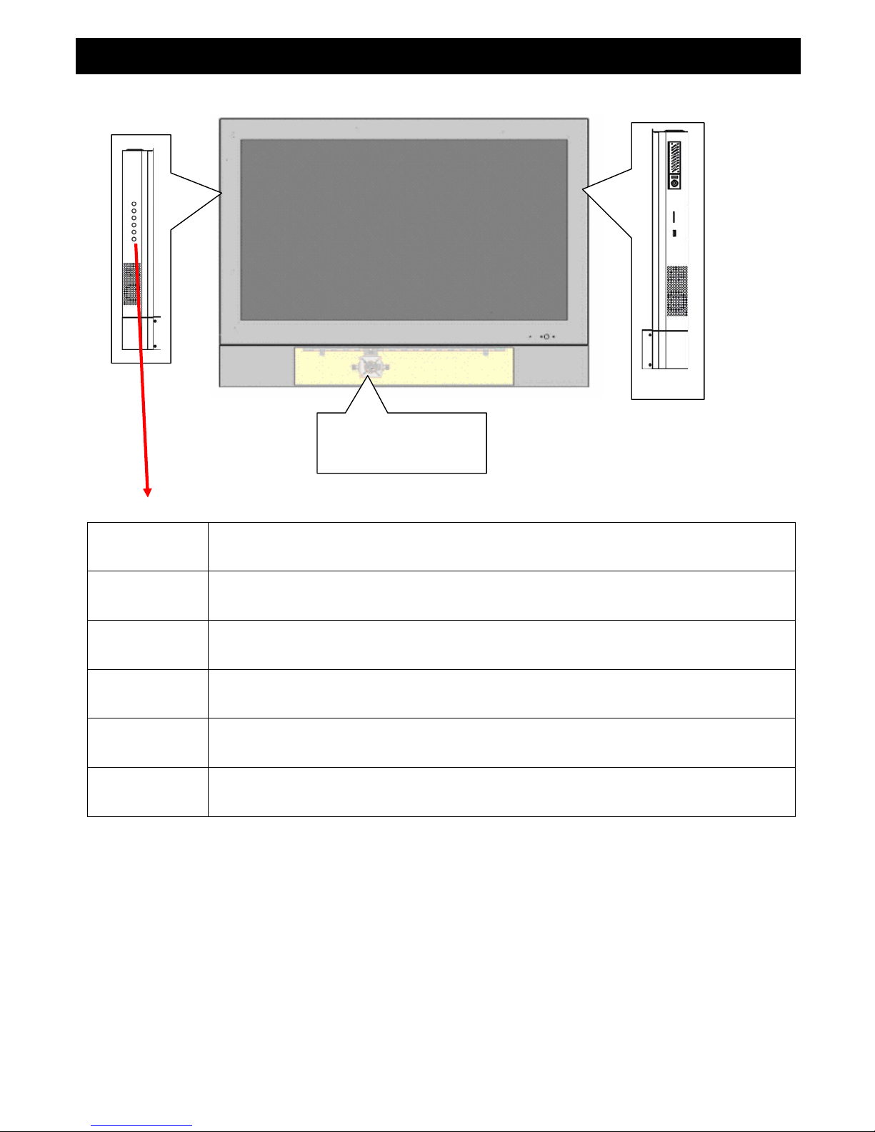
1. PVM I / O
Storage:
HDD
SD
USB
Camera1
Camera 2 (Option)
Keypad
Enter Go to sub-level menu.
Menu Push this button to display the main OSD menu.
Up Use this button to select the menu item.
Down Use this button to select the menu item.
Source The button use to select input source while the all of OSD is off.
Power Power On / Off the PVM device .
6

1.1 Rear Panel
DIDO
Camera1/Camera 2
MIC Input
VGA / DVI AV Audio Input
Camera1/Camera 2
Input (BNC type)
Ethernet VGA Input
DVI Input
AV video input
Audio In
RS485
DVI Input DVI Connector input
VGA Input VGA Connector input
Ethernet RJ45 Cable in
CAM1 BNC Connector for Camera 1 video input
CAM2 BNC Connector for Camera 2 video input
Video AV video input
Audio (L) AV audio input , RCA type (Left)
Audio (R) AV audio input , RCA type (Right)
MIC 1 IN The microphone audio in for camera 1
MIC 2 IN The microphone audio in for camera 2
Line IN The Audio Cable in for VGA / DVI
RS485 RS485 Connector for Speed Dome
DIDO Alarm in / Alarm out
PIN define :
Alarm in 1 (red) , Alarm in 2 (orange), Ground (black)
Alarm out 1-1 (yellow), Alarm out 1-2 (blue)
Alarm out 2-1 (green), Alarm out 2-2 (purple)
Notice :
1. The front panel can build in Camera 2 (option) , it also can connect camera 1 and
Camera 2 from rear panel .
2. The rear panel cameras are the first priority than the build in cameras.
7
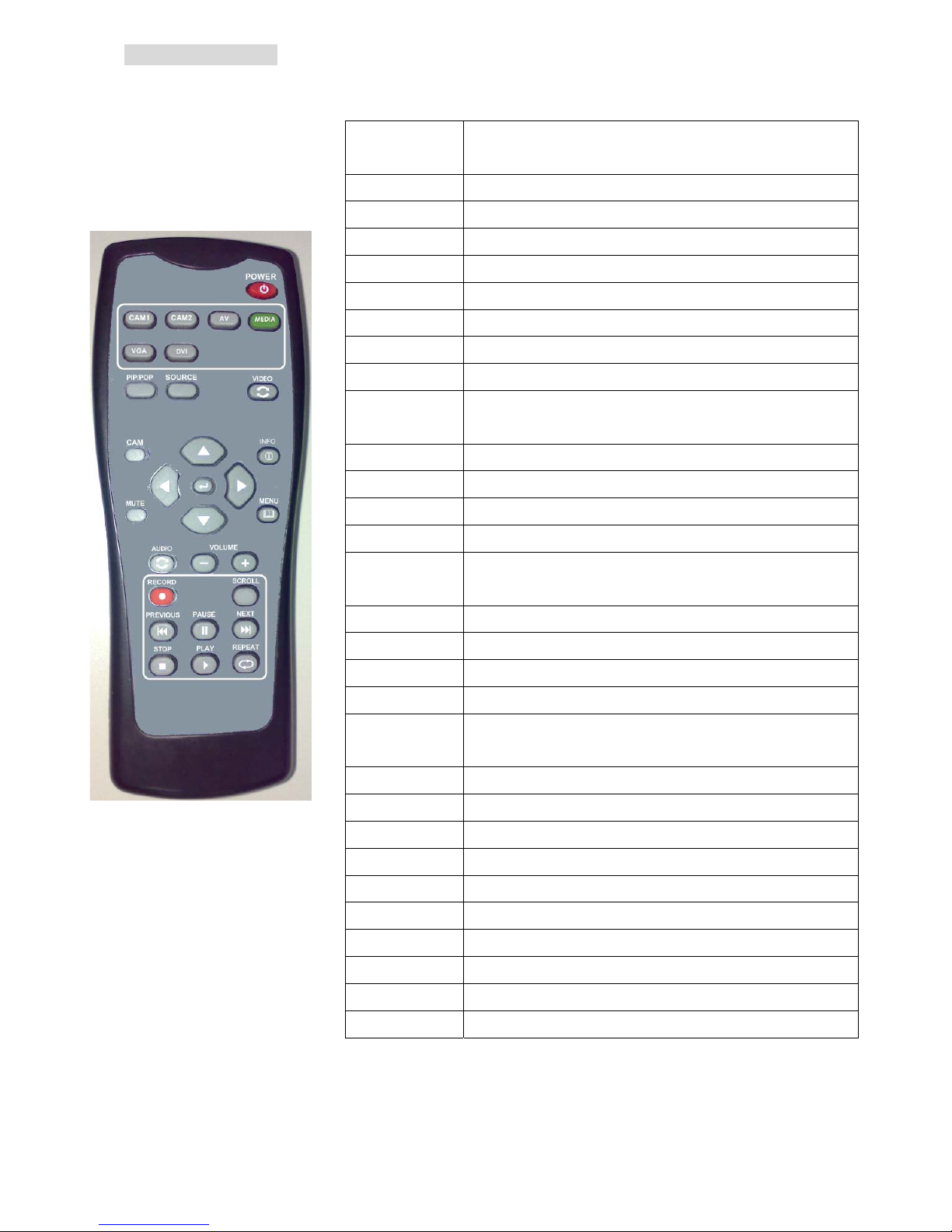
1.2 Remote Controller
Power Use this button to turn the power on and off when
the main power is supplied
Cam1 Direct to select the internal camera source input
Cam2 Direct to select the extent camera source input
AV Direct to select the AV source input
Media Direct to select the media source input
VGA Direct to select the VGA source input
DVI Direct to select the DVI source input
PIP/POP Use this button to adjust the PIP window size
Source Use this button to select the PIP source input.
Video Swap Use this button to swap the window ether main or
PIP.
Up Use this button to select the menu of the item
Down Use this button to select the menu of the item
Left Use this button to adjust value of function.
Right Use this button to adjust value of function.
Enter Use this button to execute adjustment or to
select one item of next level.
CAM Select the camera control (CAM1 or CAM2)
Mute Mute the audio.
Info Pop-out the source and DVR status message
Menu Push this button to displays the main OSD menu.
Audio Use this button to swap the live audio out ether
main or PIP.
Volume - Adjust the volume down. (Zoom out)
Volume + Adjust the volume up. (Zoom in)
Record Start record or Stop
Scroll Enable scroll text or Stop.
Play Playback media from hdd
Stop Stop playback
Repeat Repeat current media
Previous Go back previous media
Pause Pause the playback
Next Skip to next media
8

1.3 Display mode
pPIP mode
Source :AV
oDisplay Info IconsnSource : CAM1
nMain source ,the source could be the CAM1/ CAM2 / AV / VGA / DVI / Media
oDisplay information Icons
(Please see below icons indicated mapping table ) .
pPIP Mode, when main source is CAM1 then the PIP source could be the
CAM2 / AV / VGA / DVI / Media
9
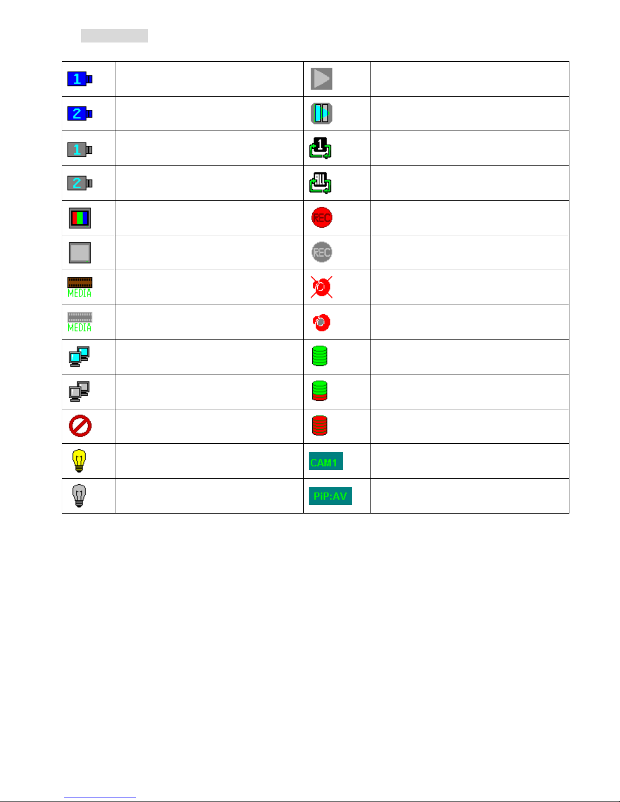
1.4 Display Icon
Display Info (Icons indicated)
Camera 1 source active
Playing the media file
Camera 2 source active
Pause the playing media file
Camera 1 (No signal input )
Media source repeat file 1
Camera 2 (No signal input )
Media source repeat all files
AV source active
DVR recording
AV source (No signal input )
DVR stop record
Media source active
Audio Mute
Media source (No signal input )
Audio active
Client connected
HDD usage 0 %
Client disconnected
HDD usage 40 %
No audio signal input
HDD full (usage 100 %)
CDS control set on Main source :CAM1
CDS control set off PIP mode , PIP source:AV
10
2. OSD Menu Setup
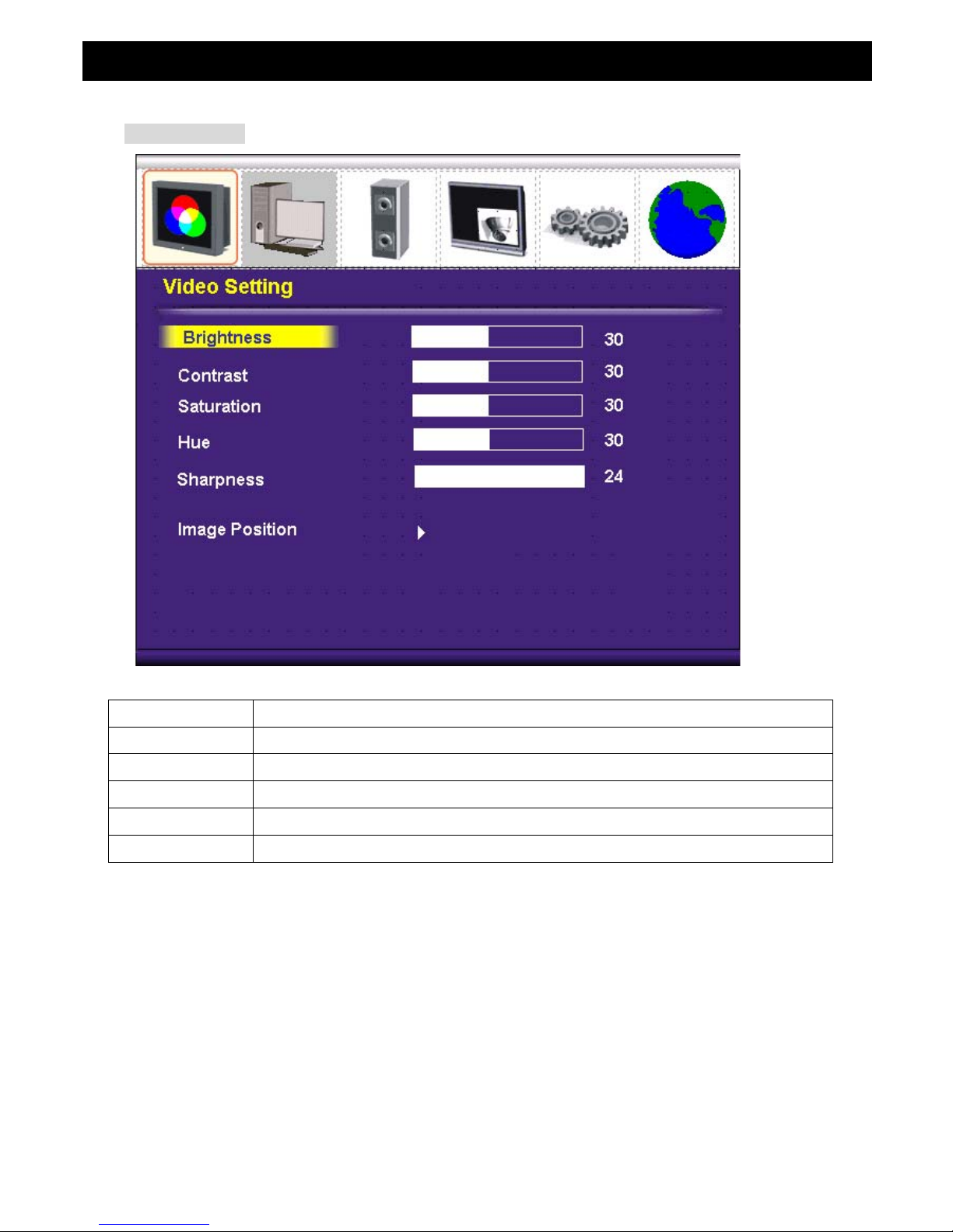
2.1 Video Setting
Brightness Adjusts the overall picture shade and brightness , 0 ~ 100
Contrast Adjusts the contrast between light and dark areas of the picture. 0 ~ 100
Saturation Adjusts the intensity of the color. 0 ~ 100
Hue To determine the lightness and colorfulness of the picture, 0 ~ 100
Sharpness Sets the desired sharpening enhancement to the picture 0 ~ 24
Image Position adjustment for horizontal / vertical position
11
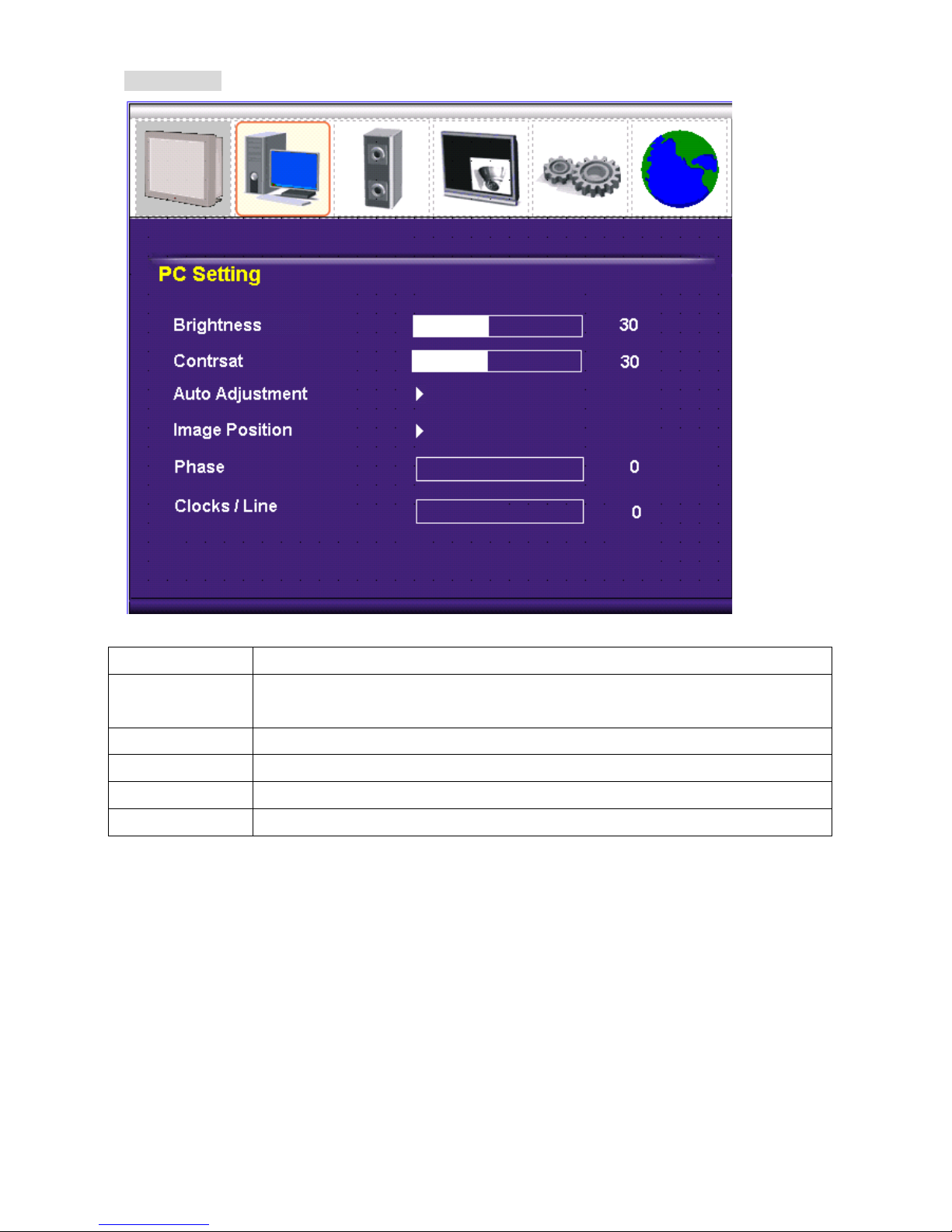
2.2 PC Setting
Brightness Adjusts the overall picture shade and brightness.
Contrast Permits adjustment of contrast between light and dark areas of the
picture.
Auto Adjustment Picture adjustment automatic correction, like clock and phase.
Image Position Allows adjustment for horizontal / vertical position
Phase To adjust the clock phase of VGA signal 0 ~ 31
Clock / Line To adjust the H. total of VGA signal
12
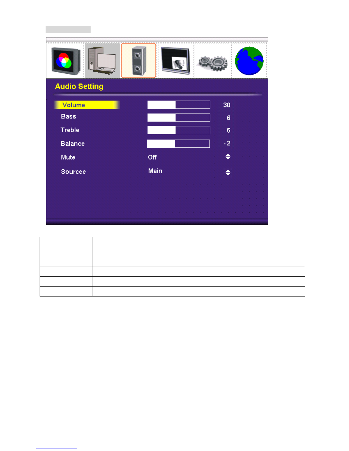
2.3 Audio Setting
Volume Controls built-in speakers’ output volumes.
Base Adjusts the tone to low frequency part of the sound. 0~ 14
Treble Adjust the high or acute of the sound. 0 ~ 14
Balance Adjusts the softness of loudness of notes in the sound. -10 ~ +10
Mute To disable the audio function. (On / Off)
Source Select the audio source . (Main or sub source , only on PIP enabled)
13
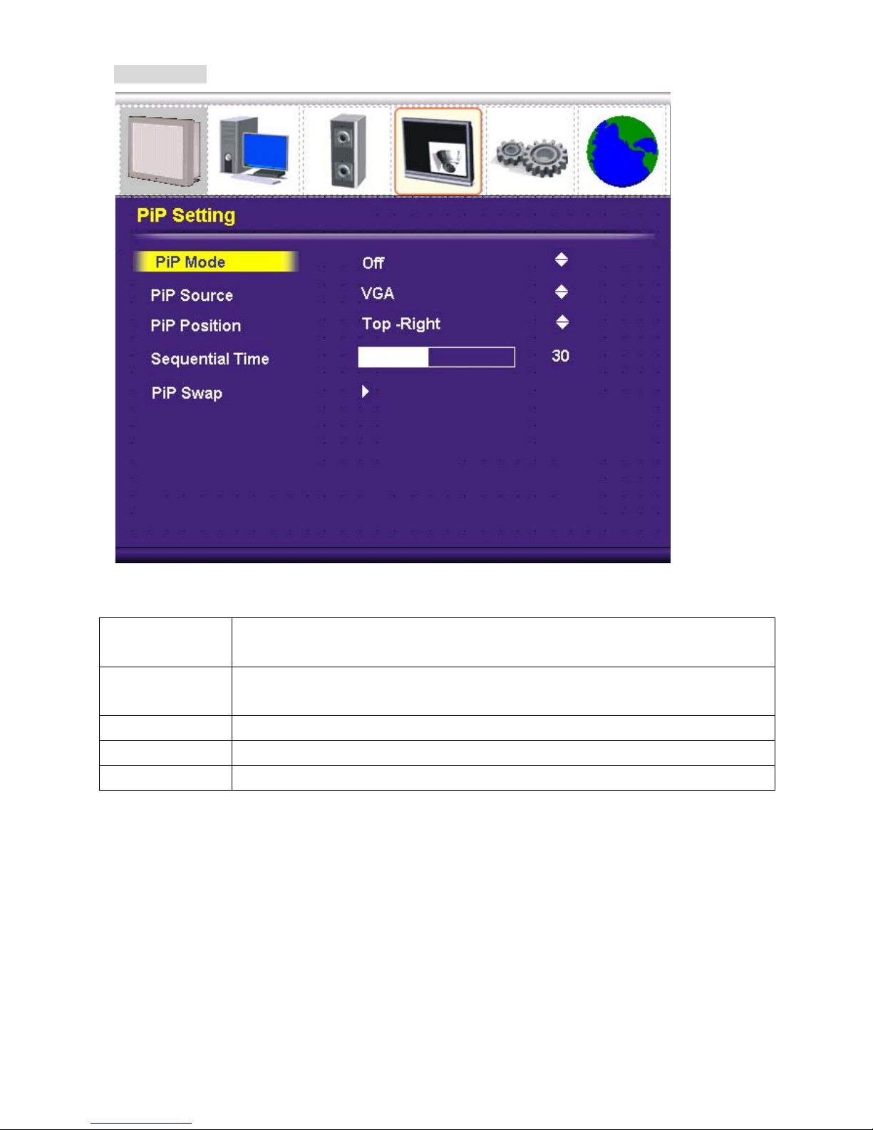
2.4 PIP Setting
PIP Mode Select the PIP mode display , ( Off / Small / User / Side-by Side / Side-by
Side Tall )
PIP Source Select the PIP source , ( CAM2 / DVI / VGA / Media / AV )
Note : main window and PIP window should be a different source .
PIP Position Adjust the PIP position (Top-Left / Top-Right / Bottom- Right / Bottom- Left)
Sequential Time Time of the video change the PIP source ( 0 ~ 100 seconds)
PIP Swap Swap the source between the main and PIP window
14
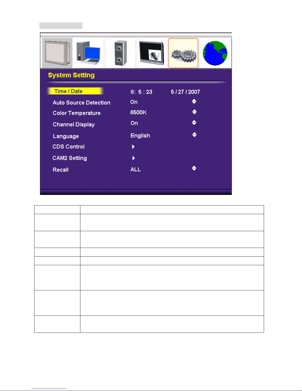
2.5 System Setting
Date / Time Setup the system date and time .
Auto Source
Detection
Auto detect source when the singal is lost (excluding PIP source)
(On / Off )
Color
Temperature
Selects color temperature of either 6500°K or 9300°K.
Channel Display Enable / Disable display the source message . (On / Off )
OSD Language Select the OSD language. (English )
CDS Control Power control by CDS function . (On /Off )
Power off level 100~300
Power on level 500 ~ 1000
CAM2 Setting On/off
Protocol (Pelco P / Pelco D)
Baud Rate (2400 / 4800 / 9600)
Recall Recall the user setting (ALL / DVR / LCD )
15
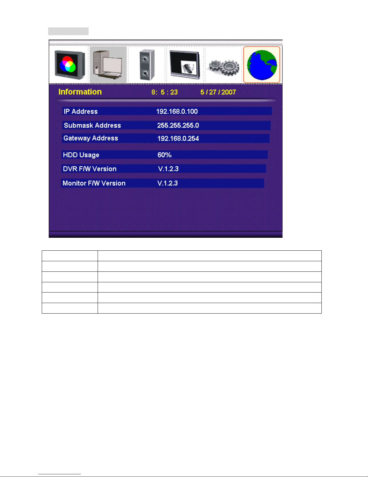
2.6 Information
IP Address Display the PVM IP address. (default is 192.168.0.2)
Submask Display the subnet mask. (default is 255.255.255.0)
Gateway Display the gateway IP address. (default is 192.168.0.1)
HDD Usage Display the hard disk record usage
DVR Version Display the DVR F/W version
Monitor Version Display the LCD monitor F/W version
16

3.0 Main Menu
3. Camera OSD Menu Setup
Main menu
General È
Ae È
Wdr È
Day/Night È
Awb È
Privacy È
Special È
Message È
Initial OFF
Exit È
Notice :
1. CAM1 default ID is 1, CAM2 default ID is 2.
2. Switch to CAM1 or CAM2 will display with full screen mode.
3. Can’t change input source in CAM control mode. Must leave to the Live mode first.
17

3.1 General Menu
CameraID 1
Baud rate 9600
Sync INT
V phase NA
Initial ON
EXIT È
General menu
Camera ID Set Camera ID 1~255
Baud rate Baud rate is a serial communication rate that use to measure how fast data
is moving. Baud rate is able set at 2400、4800、9600、19200 four different
serial communication rates.
Sync Set Sync function to internal mode
V phase Set V phase to N/A.
Initial Initial General menu’s setting back to the factory settings
Exit Return to Main menu
18

3.2 AE Menu
19
Brightness Brightness level adjustment. Adjust range: 0~36.
Brightness function works only if WDR mode is OFF.
(When WDR mode is on, brightness function will become N/A and not
adjustable.)
AGC Max Auto Gain Control Maximum (AGC Max) function.
Adjust range: 0~255.
(When WDR mode is on, AGC Max function will become N/A and not
adjustable)
MGC Adj Manual Gain Control Adjustment (MGC Adj) function. Users are only able to
make an adjustment when Shutter mode becomes fixed such as 1/125.
(When WDR mode is on, MGC Adj function will become N/A and not
adjustable.)
Flicker When Flicker function is ON, fixed electronic shutter will be
1/100(NTSC) or 1/120(PAL). This function will work only if camera’s
WDR function set as OFF.
Shutter mode MIRIS means auto shutter selected otherwise users are able to set the
shutter at a fixed rate
DSS max Digital Slow Shutter (DSS). Adjust range: 2~160 Field。
Initial Initial Auto Exposure (AE) menu’s setting back to factory settings.
Exit Return to Main menu
Brightness 16
Agc max 160
Mgcadj NA
Flicker OFF
Shutter MIRIS
Dssmax OFF
Initial ON
Exit È
Ae menu

3.3 WDR Menu
20
WDR mode Wide Dynamic Range (WDR) ON/OFF switch
WDR level When WDR is ON, users are able to adjust WDR level from 0 to 255.
Backlight Backlight ON/OFF Switch. Backlight Compensation (BLC) function works
only if WDR function is OFF.
BLC level BLC level setting range from 0 to 15, it only works when WDR function is
OFF
BLC wind BLC wind setting. BLC wind function allows users set BLC wind position (10
positions in total).,CENTERS、CENTERL、TOPS、TOPL、BOTTOMS、
BOTTOML、LEFTS、LEFTL、RIGHTS、RIGHTL
Initial Initial WDR menu’s setting back to factory settings.
Exit Return to Main menu
WDR menu
Wdr mode ON
Wdr level 128
Backlight NA
Blclevel NA
Blcwind NA
Initial OFF
Exit È
Table of contents


