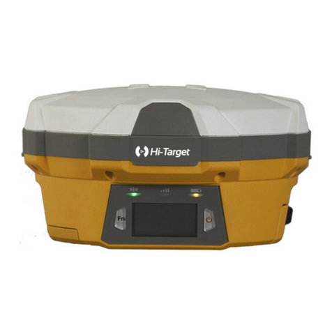
Hi-Target GPS VNet6 Plus User manual

ADD: Building13, Tian’An Technology Zone HQ center, No.555, the North of Panyu RD, Panyu District 511400, Guangzhou, China.
VNet6 Plus User Guide
Hi-Target Surveying Instrument Co., Ltd.
All Rights Reserved

ADD: Building13, Tian’An Technology Zone HQ center, No.555, the North of Panyu RD, Panyu District 511400, Guangzhou, China.
Manual Revision
File number:
Revision
Date
Revision Level
Description
2017-06-19
1
VNet6 Plus User Guide

ADD: Building13, Tian’An Technology Zone HQ center, No.555, the North of Panyu RD, Panyu District 511400, Guangzhou, China.
Preface
Introduction
Welcome to VNet6 Plus User Guide. This introduction describes how to use this
product.
Experience Requirement
In order to help you use Hi-Target series products better, Hi-Target suggests you
carefully read the instruction. If you are unfamiliar with the products, please refer
to www.hi-target.com.cn or contact Hi-Target Technical Group.
Tips for safety use
Notice: The contents here generally are special operations, and
need your special attention. Please read the contents carefully.
Exclusion
Before using the products, please carefully read the operating instruction, and it
will help you better use it. Hi-Target Surveying Instrument Co., Ltd will not assume
the responsibilities if you fail to operate the product according to the requirements
in operating instruction, or operate the product wrongly because of failing to
understand the operating instruction.
Warning: The contents here generally are very important. Such
wrong operation may make the machine damaged, make the data lost, even
breaks down the system and endangers personal safety.

ADD: Building13, Tian’An Technology Zone HQ center, No.555, the North of Panyu RD, Panyu District 511400, Guangzhou, China.
Hi-Target is committed to constantly perfect product functions and performance,
improve service quality and reserve the rights to change the contents in operating
instruction without separate notice.
We have checked the consistency between contents in instruction and software &
hardware, without eliminating the possibility of deviation. The pictures in
operating instruction are only used for reference. In case of inconformity with
products, the products shall prevail.
Technology and Service
If you have any technical issues, you can call Hi-Target technology department for
help, we will answer your question in time.
Advice
If you have any comments and suggestions, please call us or Dial the national
hotline: +86 400-678-6690. Your feedback information will help us to improve the
quality of the product and service.

ADD: Building13, Tian’An Technology Zone HQ center, No.555, the North of Panyu RD, Panyu District 511400, Guangzhou, China.
Vnet6 Plus User Manual
Chapter1 Introduction................................................................................................................7
1.1 Introduction..........................................................................................................................7
1.2 Features................................................................................................................................8
1.3 Use and precautions...........................................................................................................10
Chapter 2 GNSS receiver Introduction ...................................................................................13
2.1 Front Panel.........................................................................................................................13
2.2 Back Panel .........................................................................................................................14
2.3 Mainframe..........................................................................................................................14
2.4 Button Function .................................................................................................................15
2.5 Indicator lights ...................................................................................................................16
2.6 LCD ...................................................................................................................................17
2.7 External port ......................................................................................................................20
Chapter 3 WEB Administration ..............................................................................................22
3.1 User login...........................................................................................................................22
3.2 WEB interface for administration......................................................................................24
3.3 Elementary info .................................................................................................................25
3.4 Home page .........................................................................................................................26
3.5 System info ........................................................................................................................27
3.6 working mode ....................................................................................................................30
3.7 File management................................................................................................................39
3.8 Advanced setting................................................................................................................42
3.9 User management ..............................................................................................................51
Chapter 4 Basic operations.......................................................................................................53
4.1 Architecture model.............................................................................................................53
4.2 Basic composition and connection ....................................................................................53
4.3 Connector installation........................................................................................................54
4.4 Network connection...........................................................................................................56
4.5 LCD and button operation .................................................................................................62
4.6 Set the base station.............................................................................................................64
4.7 Add data record..................................................................................................................66
4.8 Add network transmission .................................................................................................68

ADD: Building13, Tian’An Technology Zone HQ center, No.555, the North of Panyu RD, Panyu District 511400, Guangzhou, China.
4.9 Data download ...................................................................................................................70
4.10 Firmware upgrade............................................................................................................73
4.11 Register the receiver ........................................................................................................75
Chapter 5 Appendix ..................................................................................................................78
5.1 Reset ..................................................................................................................................78
5.2 VNet product technical performance parameters table......................................................79
5.3 Standard configuration table..............................................................................................80

Surveying the world,Mapping the future.
ADD: Building13, Tian’An Technology Zone HQ center, No.555, the North of Panyu RD, Panyu District 511400, Guangzhou,
China.
Chapter1 Introduction
1.1 Introduction
HI TAGET GNSS receiver VNet series (referred to as "receiver" or "GNSS
receiver") products include: VNet6, VNet6 Plus, VNet8 and so on. This
manual mainly introducing GNSS receiver VNet6 Plus.
The VNet Series GNSS reference receiver installed with the high-
performance microprocessors, high-capacity, high-speed flash memory
and battery, multi-communication port and military grade industrial
standard design level. With built-in firewall, data encryption transmission
protocol, make the GNSS receiver more accurate, easy to use , better
availability, more stable operation. On the strength of Hi-Target’s
sophisticated GNSS technology and the years of experiences in
establishing CORS/VRS system, the VNet series GNSS reference receiver
will provide you with reliable communication, better performance,
stronger stability and safety.
Notice:
1. The specific configuration is write on the list.
2. Please carefully open the box to confirm. If you find any loss
of this product and accessories, damages, please contact your
local office or dealer immediately.
3. Please read the instruction manual carefully before carrying,
using and handling.

Surveying the world,Mapping the future.
ADD: Building13, Tian’An Technology Zone HQ center, No.555, the North of Panyu RD, Panyu District 511400, Guangzhou,
China.
1.2 Features
1.Based on the Linux operating system
Based on the embedded Linux operating system kernel, is a real multi-user,
multi-tasking, multi-platform operating system. With its system stability,
management functions, powerful network; the Vnet6 Plus is suitable for a
long time unattended continuous work.
2. Excellent GNSS multi-constellation tracking performance
220 Channels with Trimble OEM mainboard, support GPS, GLONASS,
BDS, GALILEO and other global satellite navigation and positioning
system, can maximize the tracking ability of all visible GNSS satellite
signals, thereby improving the measurement accuracy and real-time RTK
measurement performance.
3. 50 Hz updating rate
Support high frequency data updating, data updating rate up to 50 Hz, and
maintain the best observation quality of the data and the independence of
the observation value;
4.Multi-task function
The GNSS receiver can deal with multiple task operations at the same time
and simultaneously download, release different types of RTK or RTD data
while continuously tracking and recording satellite data.
5. Multi transmission mode
With UHF radio, data line Modem, broadband port, Fax Modem, TCP / IP,

Surveying the world,Mapping the future.
ADD: Building13, Tian’An Technology Zone HQ center, No.555, the North of Panyu RD, Panyu District 511400, Guangzhou,
China.
built-in 3G / 2G wireless communication function, can use the Internet,
wireless network for data transmission and broadcast differential data.
6.Massive data management function
Built-in 64GB high-performance storage and can support the maximum of
less than 1TB industrial-grade U disk storage or external USB storage
devices; support U disk download, FTP download and remote download;
and the receiver also has a loop storage function.
7.High-precision measurement technology
The Hi-Target’s sophisticated GNSS technology make sure the accuracy
reaches millimeter, make sure the data have the reliable quality.
8. Excellent compatibility
With excellent compatibility, real-time output CMR, RTCM, RTCMV3,
RTCM32, and other formats of correction data to compatible with third
part CORS system seamlessly, which can be used to new and extend
enhance CORS system. Also output high-precision real-time GNSS raw
data.
9. Remote access function
Easy to using the Network for remote access the reference stations, easy
for remote control.
10. Multi data interface
Equipped with three RS232 ports, two USB ports, one Wi-Fi, one
Bluetooth communication port, one 3G / 2G communication port, one

Surveying the world,Mapping the future.
ADD: Building13, Tian’An Technology Zone HQ center, No.555, the North of Panyu RD, Panyu District 511400, Guangzhou,
China.
Ethernet port, one RS485 port, one external clock port, one PPS output port,
fully meet the reference Station requirements.
11.Multi-mode power supply
Built-in large capacity lithium battery, can work for 24 hours (related to
configuration); external voltage power supply: 7VDC ~ 36VDC; support
battery, solar and wind power supply.
1.3 Use and precautions
Although the VNet series (ground-based) GNSS receiver is based on
military standard design, it is anodized with an aluminum alloy, but the
precision instruments require careful use and maintenance.
WARNING: The receiver must be used and stored within
the specified environment. Please refer to the Appendix:
VNet product technical performance parameters table.
Avoid using the receiver in extreme environments.
The VNet6 Plus (ground-reinforced) GNSS receiver uses anodized
aluminum alloy for the shell, but should also be kept as dry as possible.
And in order to improve the stability of the receiver and extend the service
life, please avoid the receiver exposed to extreme environments, such as:
1. Damp
2. The temperature is higher than 75 ℃
3. The temperature is less than -40℃
4. Corrosive liquid or gas

Surveying the world,Mapping the future.
ADD: Building13, Tian’An Technology Zone HQ center, No.555, the North of Panyu RD, Panyu District 511400, Guangzhou,
China.
Do not place the GNSS antenna near sources of electricity and strong
interfering signals:
1. Oil (spark plug)
2. TV and computer monitors
3. Generator
4. Electric motorcycle
5. DC - AC power conversion equipment
6. Fluorescent light
7. Power switch
When selecting the position of the GNSS reference station for continuous
operation, notice the following:
The site should be easy to place the receiving device and have a wide field
of vision. Field height above 10 degrees should not have obstacles, so as
not to absorb or block the GNSS signal, as shown in Figure 1-1:
Figure 1-1
1.Near the site should avoid the large area of water or strong interference
with the satellite signal, to reduce the impact of multi-path effect.
2.The site should be away from high-power radio transmission sources
(such as television stations, microwave stations, etc.,) it's better to keep a

Surveying the world,Mapping the future.
ADD: Building13, Tian’An Technology Zone HQ center, No.555, the North of Panyu RD, Panyu District 511400, Guangzhou,
China.
distance more than 200m; away from high-voltage transmission lines, the
distance should more than 50m to avoid electromagnetic interference on
the GNSS signal.
3.To provide a stable device to fix the antenna.
4.To provide reliable and stable power supply and communication network.
5. Suitable placement and protection of GNSS reference station equipment.
6.Select the traffic developed place, easy to arrive for inspection and
maintenance.

Surveying the world,Mapping the future.
ADD: Building13, Tian’An Technology Zone HQ center, No.555, the North of Panyu RD, Panyu District 511400, Guangzhou,
China.
Chapter 2 GNSS receiver Introduction
2.1 Front Panel
Figure 2-1 Overall appearance of the receiver
Figure 2-2 Front panel
1. MiniUSB port: Reserved
2.TF Card slot:Install TF(micro SD) card to Expand storage capacity
3.SIM Card slot:Install standard SIM card for 3G / 2G wireless network
communication
4.LCD: Display receiver status information
5.Indicator light:Indicates information such as receiver tracking status,
network status, power status, and so on
6.USB port:Connect a USB flash drive or USB storage device for storing
/ downloading data and upgrading the firmware
7. Button panel: For query and configure the receiver.
Front Panel
Back Panel
1
2
3
4
5
6
7

Surveying the world,Mapping the future.
ADD: Building13, Tian’An Technology Zone HQ center, No.555, the North of Panyu RD, Panyu District 511400, Guangzhou,
China.
2.2 Back Panel
Figure 2-3 back panel
1.DB9 port: Data output and connect to external devices
2.GNSS antenna: For connect the antenna
3.Power port: Power input port
4. External clock: TNC Socket for connecting external atomic clocks
5. Ventilation holes: Waterproof ventilation holes
6.External extension:12V DC power output, RS232 debugging port,
RS485/RS422 Communication port, hardware restart port
7.LAN port:Wire network connection port
8.3G antenna: Connect the 3G / GPRS antenna port
9.Five-core socket: Differential data output, external data link connection;
auxiliary power supply input
10.PPS output: PPS output port
11.Ground Point: Lighting protection grounding port
2.3 Mainframe
The mainframe uses an all-aluminum alloy metal housing and uses an
anodizing process, as shown in Figure 2-4:
4
5
6
10
11
9
8
7
3
2
1

Surveying the world,Mapping the future.
ADD: Building13, Tian’An Technology Zone HQ center, No.555, the North of Panyu RD, Panyu District 511400, Guangzhou,
China.
Figure 2-4 Mainframe
2.4 Button Function
Table 2.1 Button Description
Operation
Description
Click
button operation< 0.5 s
Double Click
button operation interval <1 s
Long Press
button operation>6 s
Table 2.2 Button Function Description
Button
Name
Function
status
Power button
Double-click:turns off / on the
LCD
See in
the LCD
Single click:Boots, modify the
parameters and confirm
Long Press:turn off
Left button
Single click:Move left or up

Surveying the world,Mapping the future.
ADD: Building13, Tian’An Technology Zone HQ center, No.555, the North of Panyu RD, Panyu District 511400, Guangzhou,
China.
Right button
Single click :Move right or
down
Function
Button
Cancels or interface switch
See in
the
LCD
Combination
Button
Press the Fn button and click
the power button To upgrade
the kernel;
The
satellite
lights
are
flashing
2.5 Indicator lights
LCD information
Status
Function
Satellite light
Always bright
Satellite tracked
Always off
Satellite untracking
Record light
Quick flashing
Record interval <1 second
Slow flashing
Recording interval≥1 s
Always off
Recording stops
Network light
Always bright
Connected
Always off
No network connection
Quick flashing red
Alarm

Surveying the world,Mapping the future.
ADD: Building13, Tian’An Technology Zone HQ center, No.555, the North of Panyu RD, Panyu District 511400, Guangzhou,
China.
Power / Alarm Light
Always yellow
External power supply
Always green
Battery powered
Notice: double-click the power button to open the LCD display,
the lights will turn off except for the network light.
2.6 LCD
Status display normally will show the Status of satellites, IP, port and
Network connection status.
1.Status Display
Figure 2-5 Main parameter information
1-Common satellite Number; 2-satellite Lock Status;3-Alarm
Status;4 - Wi-Fi Status; 5-3G Network Status; 6-IP Address; 7-Total
satellite number ;8-Power supply / battery power; 9-3G Signal
strength;10-3G Network transmission status;
LCD status
Shows
meaning
Alarm status
Normal status
Alarm
Wi-Fi status
Wi-Fi is off
1
2
3
4
5
6
7
8
9
10

Surveying the world,Mapping the future.
ADD: Building13, Tian’An Technology Zone HQ center, No.555, the North of Panyu RD, Panyu District 511400, Guangzhou,
China.
Wi-Fi is on
3G network status
The 3G module is off
The 3G module is on
3G network status
Power supply
Connected to a public network
External power supply
Battery powered
3G network
transmission status
No data transmission
Data transmission
Figure 2-6 Data transfer status
1- Total network stream– Enabled network stream; 2- Enabled data record
stream; 3- Enabled serial port number
Figure 2-7 Coordinate information
1 Latitude -;2- Longitude;3-Elevation;4-UTC time
1
3
2
1
2
3
4

Surveying the world,Mapping the future.
ADD: Building13, Tian’An Technology Zone HQ center, No.555, the North of Panyu RD, Panyu District 511400, Guangzhou,
China.
Figure 2-8 Satellite information
1-Satellite number of BDS;2- Satellite number of GPS;3- Satellite number
of GLONASS;4- Satellite number of other;5- Satellite map of the sky
Figure 2-9 Receiver status information
1-Receiver SN number;2-Version;3-Motherboard version;4-Expire data;
Figure 2-10 Status information
2.Display setting
1
2
3
4
5
4
1
2
3

Surveying the world,Mapping the future.
ADD: Building13, Tian’An Technology Zone HQ center, No.555, the North of Panyu RD, Panyu District 511400, Guangzhou,
China.
Figure 2-11 Setup menu
1- Data record;2- Network settings;3- Data download;4- System settings;
Figure 2-12 System settings
1- Firmware Upgrade;2- Restore the default IP;3- reset;4- Reset the
motherboard;
2.7 External port
Table 2.5 External port descriptions
Panel
Panel
Name
Panel
instructi-
ons
Physical
port
Function
Front
Panel
MiniUSB
port
/
MiniUSB
/
USB port
/
USB-A
Data storage / download, upgrade
firmware ,available for U disk and USB
removable storage
TF/
SIM Card
slot
TF/SIM
Card slot
TF card: storage data and ROM; SIM
card: 3G / 2G wireless network
communication;
Back
GNSS
GNSS
TNC
Connect the GNSS antenna
4
3
1
2
1
2
4
3
Table of contents
Other Hi-Target GPS Receiver manuals
