Hi-Tec HFP-30 User manual

Instruction Manual
Introduction
Contents
Programming
Congratulations on the purchase of the HFP-30. The HFP-30 is
designed to program all Hitec Digital Programmable Servos (D Series,
5xxx/7xxx, and Brushless) as well as test any brand servo.
Layout
Powering On
Main Screens
1. Main Programming Screen
2. Main Servo Test Screen
Test Mode
1. Manual Test
2. Auto Test
3. Auto Deadband Testing
4. Settings
D Series Program Mode
1) Set EPA/Neutral
2) Servo Sync
3) Set Rotation (CW_CCW)
4) Set Deadband (DB_Width)
5) Set Speed
6) Set ID (ID_Read)
7) Set Failsafe
8) Set Soft Start
9) Factory Reset (Factory Default Set)
5/7 Series Program Mode (For 5xxx*/7xxx Servos)
1) Set EPA/Neutral
2) Servo Sync
3) Set Rotation (CW_CCW)
4) Set Deadband (DB_Width)
5) Set Speed
6) Set Failsafe
7) Set Resolution
8) Set Overload Protection (OLP)
9) Factory Reset (Factory Default Set)
1. Adjust Dial
2. Back Button
3. Analog Dial for Pulse Adjustment
4. USB Port
5. Test/Program Select Switch
6. Battery/Receiver Port
7. Servo Sync Port
8. Servo Port
9. LCD
B Series Program Mode (BLDC Servos)
1) Set EPA/Neutral
2) Servo Sync
3) Set Rotation (CW_CCW)
4) Set Deadband (DB_Width)
5) Set Speed
6) Set Failsafe
7) Set Soft Start
8) Factory Reset (Factory Default Set)
The HFP-30 is powered by a user provided 4.8VDC to 7.4VDC battery
pack plugged into the Batt/RX slot. Optionally, a receiver with the
correct adapter can power the unit.
Note: Make sure the battery voltage corresponds to the servos
being used. Do not use a 7.4V battery with a servo designed for
6V and under, or damage may occur to the servo.
Depending on the position of the Test/Program select switch, the
following screens will appear when powered on. Once powered on,
it is possible to toggle between the screens using the Test/Program
switch.
Main Programming Screen
Use the Adjust Dial to switch between the three dierent series of
servos. Once the correct one is highlighted, press the Adjust Dial to
enter.
1
5
3
6
4
2
9
7
8
Layout
Contents
Powering On
Main Screens
Dial Button
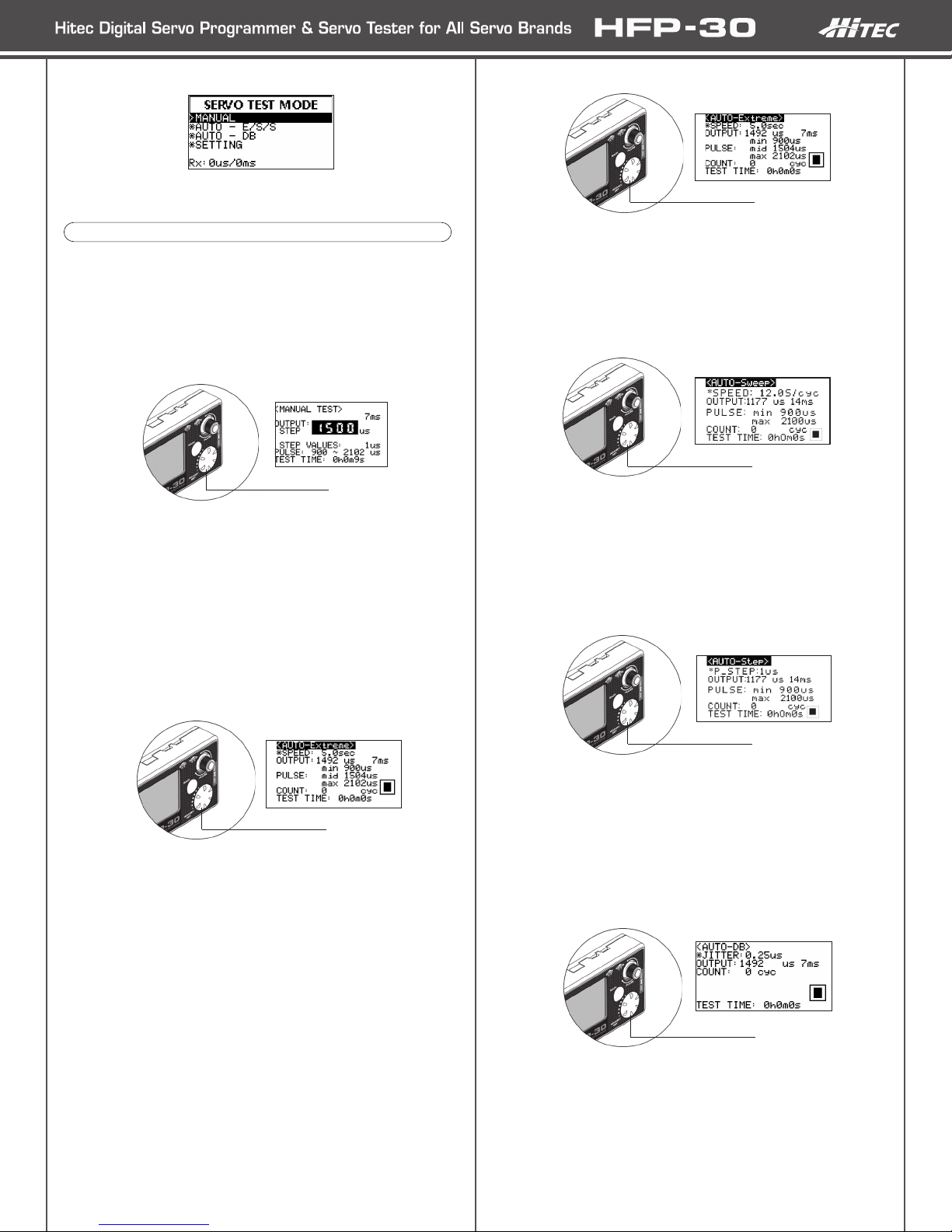
AUTO-Extreme
With this highlighted, press the Adjust Dial. This will select the Test
Mode and show a ‘Pause’ indicator in the lower right of the screen.
Pressing the Adjust Dial again will select ‘Play’ and the servo will
start moving. The servo speed is adjusted by turning the Adjust Dial.
Press the Adjust Dial to ‘Pause’ or the BACK button to switch to a
dierent Auto Test Mode.
AUTO-Sweep
With this highlighted, press the Adjust Dial. This will select the Test
Mode and show a ‘Pause’ indicator in the lower right of the screen.
Pressing the Adjust Dial again will select ‘Play’ and the servo will
start moving. The cycle speed is adjusted by turning the Adjust Dial.
Press the Adjust Dial to ‘Pause’ or the BACK button to switch to a
dierent Auto Test Mode.
AUTO-Step
With this highlighted, press the Adjust Dial. This will select the Test
Mode and show a ‘Pause’ indicator in the lower right of the screen.
Pressing the Adjust Dial again will select ‘Play’ and the servo will
start moving. The Step increments are adjusted by turning the Adjust
Dial.
Press the Adjust Dial to ‘Pause’ or the BACK button to switch to a
dierent Auto Test Mode.
AUTO-DB (Deadband)
Use the Adjust Dial to highlight AUTO-DB and press it to enter the
menu. The Auto Test will check the servos Deadband. When in the
menu, press the Adjust Dial to begin the Test. A ‘Play’ symbol will be
displayed in the lower right screen. Turning the Adjust Dial will adjust
the microsecond range. The jitter range is 0.25 microseconds to
100.0 microseconds.
Press the BACK button to exit.
Dial Button
Dial Button
In this mode, all manufacturer’s servos can be tested for operation.
To begin testing servos, plug a servo into the servo slot on the
programmer and install the correct battery type in the battery slot.
Move the select switch to the TEST position.
1. Manual test
Using the Adjust Dial, highlight Manual, and press then Adjust
Dial to enter.
At this point it is possible to move the servo using the Pulse Dial.
As the dial is turned the OUTPUT box will show the current position
of the servo in microseconds.
Pressing the Adjust Dial will switch to STEP mode allowing much
ner control. Use the Adjust Dial to adjust the microseconds. Press
again to exit.
Press the BACK button to exit the menu.
1. AUTO – E/S/S Test (Extreme, Sweep, Step)
Use the Adjust Dial to highlight AUTO – E/S/S and press it to
enter the menu.
In the Auto Test menu, it is possible to switch between Extreme,
Sweep, and Step modes by turning the Adjust Dial. Each mode will
display a cycle count and how much time has passed during the
test. Before a mode is selected, the Pulse Dial will move the servo
manually.
Here’s a brief explanation of the dierent modes:
Extreme – Moves the servo through minimum, middle (neutral),
and maximum endpoints. Speed of the total movement can be
adjusted. If the movement is set faster than the servo is rated,
then the servo will not be able to move to each end point before
changing direction. The speed ranges from 0.1 second to 5.0
second.
Sweep – Moves the servo through minimum and maximum
endpoints at an adjustable speed. The speed of the Sweep is
adjustable between 2.4 seconds/cycle to 120 seconds/cycle.
Step – Moves the servo through the minimum and maximum
positions at an adjustable Pulse Step. The Step range is 0.25
microseconds to 100.0 microseconds.
Dial Button
Test Mode
Dial Button
Dial Button
Main Servo Test Screen
Use the Adjust Dial to select the desired test function. Once the
function is highlighted, press the Adjust Dial to enter.

The Settings menu is where specic test parameters can be set for
all servo test modes. Use the Adjust Dial to highlight SETTING and
press it to enter the menu.
To make adjustments to the various settings, use the Adjust Dial to
highlight it and then press the dial to enter editing mode. To change
the value, use the Adjust Dial. Either press it again to conrm and
exit or press the BACK button to exit without saving.
The dierent features that can be edited are:
GYRO MODE (ON/OFF): This is for use with specically designed
tail rotor servos. These servos generally use a dierent neutral and
endpoints than other servos. Turning this feature on will automatically
reset the pulse widths and frame rate for testing. Do not use this
setting unless the servo being tested states it is a high frame rate tail
rotor servo.
PULSE_w (Pulse Range): For setting the Pulse Width Test
parameters for a servo. The adjustments are made to middle
(neutral), minimum and maximum endpoints. To edit a point, highlight
it using the Adjust Dial and then press the dial to begin editing.
The range for each is:
Mid: 1100 – 1900 microseconds
Min: 100 – 1500 microseconds
Max: 1500 – 2520 microseconds
Note: Adjust these settings with caution. If the pulse is too wide,
the servo may stall which will cause damage.
PULSE_p (Frame Rate): The Frame Rate is how fast the signal
is sent to the servo. The lower the number the faster the signal is
sent. The range is from 3 milliseconds to 30 milliseconds. Caution is
required as analog servos cannot handle frame rates faster than 14
milliseconds. Doing so will cause damage.
STEP VALUES: The increments moved when testing. The range is
from 0.25 microseconds
to 1 microsecond.
TEST: The speed and number of cycles to test at when using AUTO
E/S/S mode.
The ranges are:
Speed: 0.1 second to 5.0 seconds.
Count: 0 - 50000 cycles.
LCD Contrast: Change the LCD screen contrast for better
personalized viewing.
SET Default: Revert all settings to their defaults.
To program the dierent series of Hitec digital servos, plug the servo
into the SERVO port of the programmer and the battery or receiver
into the BATT/RX port. Once connected, move the selector switch
to the PROG position. On the SERIES SELECTION screen, use the
Adjust Dial to select the appropriate series of the servo connected.
Press the dial to enter the menu. Each setting is selected with the
Adjust Dial. Once highlighted, press the dial to edit.
Note: It is highly recommended that the servo being programmed
is not connected to any linkage.
1. EPA Neutral Settings
Press the Adjust Dial to enter the menu. If the Pulse Dial is o center,
the program will ask that the dial is center so the indicator is at 12
o’clock. Once adjusted, the Neutral Settings screen will appear. Use
the Adjust Dial to elect either to change the Neutral position or to
skip and move on to the endpoints.
To change the Neutral position, highlight NEUTRAL, and press the
Adjust Dial to enter the edit mode. To make an adjustment, use the
Pulse Dial. To save the setting to the servo, press the Adjust Dial,
otherwise, press the BACK button to exit without making a change.
Note: Changing the neutral position to an extreme will affect the
throw of the servo’s endpoints. Try to never vary the position too
far from nominal. Also, if the neutral position is programmed, then
the endpoints must be programmed.
The endpoints can be programmed without setting the neutral
position. To do this, highlight ‘Skip to Neutral Set’ and press the
Adjust Dial.
To set the Left or Right position of the throw, highlight the direction
and press the Adjust Dial to edit. Once in editing, use the Pulse Dial
to make changes. Press the Adjust Dial to conrm or the BACK
button to exit without saving.
After making changes to the servo’s EPA settings, use the BACK
button to return to the main screen. This will save the settings to the
servo. Once back at the main screen, the recently saved changes will
show below the EPA Neutral Settings.
Note: The Hitec Digital Servos are programmed to match a .9 to
2.1 millisecond pulse width with 1.5 millisecond pulse as neutral.
When plugged into a receiver, the programmed positions might
vary slightly due to manufacturing differences from radio to radio.
EPA percentages and subtrim might have to be used for nal
adjustment.
2. Servo Sync
To match two brushless servos together, use the Servo Sync option
when programming endpoints. The rst step is to program and
save the rst servo at the desired positions. Exit the programming
mode and then place the programmed servo into the SYNC slot of
the HFP-30. Place the next servo into the servo slot and enter the
programming mode. Enter the EPA and Neutral Setting menu and
begin programming the servo. As the servo’s endpoints are adjusted,
you will see the servo in the SYNC slot move to its preprogrammed
endpoints allowing easy matching of the new servo and those
positions.
3. Rotation (CW_CCW)
Highlight CW_CCW on the main screen and press the Adjust Dial to
enter the menu. Under the Now Values will be the current rotation
direction. Below will be the value to set. Use the Adjust Dial to
change from CW to CCW. Once at the desired rotation, press the
Adjust Dial to save the value to the Now Values. Press the BACK
button to exit to the main menu.
Settings D Series Program Mode
Programming

4. Deadband (DB_Width):
Highlight DB_Width on the main screen and press the Adjust Dial to
enter the menu.
Note: Hitec Digital Servos from the factory are set to the tightest
Deadband possible by default. Even if the Deadband can be set
lower with the programmer, it will have no effect on the servo.
Once in the menu, the current Deadband is displayed under Now
Values. Use the Adjust Dial to change the value under the ‘Set
Values’. When the desired Deadband is reached, press the Adjust
Dial to save the value to ‘Now Values’. Use the BACK button to exit
to the main menu. Values for the Deadband are 1-10.
5. Speed:
At times, it is required to slow a servo down for a desired application.
Highlight Speed in the main menu and press the Adjust Dial. Once
in the menu, the current speed is displayed under ‘Now Values’. Use
the Adjust Dial to change the value under the ‘Set Values’. Once the
desired speed is reached, press the Adjust Dial to save the value to
Now Values. Use the BACK button to exit to the main menu. Values
for speed are 10 – 100%.
6. ID (ID_Read):
With D Series servos, you have the ability to assign an individual ID
number. On the main menu, the current ID is displayed. To change it,
highlight ID_Read and press the Adjust Dial to enter the menu. In the
menu, adjust the ID number and press the Adjust Dial to assign it.
Use the BACK button to exit to the main menu.
7. Failsafe:
Sometimes it is desired to have the servo go to a preset position
with loss of signal. To program and turn on the feature enter the
menu. To enter the menu, use the Adjust Dial to scroll to page 2
of the main menu and press the dial once highlighted. Follow the
on-screen instructions and center the Pulse Dial. Current Failsafe
settings are listed under ‘Now Values’. Use the Pulse Dial to set the
Failsafe position. Once set, use the Adjust Dial to turn Failsafe on or
o. Press the Adjust Dial to the save setting to the servo. The new
setting will be displayed in the ‘Now Values’. Use the Back button to
exit the menu.
8. Soft Start:
1. EPA Neutral Settings
Press the Adjust Dial to enter the menu. If the Pulse Dial is o center,
the program will ask that the dial be moved so the indicator is at 12
o’clock. Once adjusted, the Neutral Settings screen will appear. Use
the Adjust Dial to elect either to change the Neutral position orto skip
and move on to the endpoints.
To change the Neutral position, highlight NEUTRAL, press the Adjust
Dial to enter edit mode. To make an adjustment, use the Pulse Dial. To
save the setting to the servo, press the Adjust Dial, otherwise, press
the BACK button to exit without making a change.
Note: Please note that changing the Neutral position to an extreme
will affect the throw of the servo’s endpoints. Try to never vary
the position to far from nominal. Also, if the Neutral position is
programed, then the endpoints must be programmed.
The endpoints can be changed without setting the Neutral position. To
do this, highlight ‘Skip to Neutral Set’ and press the Adjust Dial. To set
the Left or Right position of the throw, highlight the direction and press
the Adjust Dial to edit. Once in editing, use the Pulse Dial to make
changes. Press the Adjust Dial to conrm or the BACK button to exit
without saving.
2. Servo Sync
To match two servos together, use the Servo Sync option when
programming Neutral and Endpoints. The rst step is to program and
save the rst servo at the desired positions. Exit the programming
mode and then place the programmed servo into the SYNC slot of
the HFP-30. Place the next servo into the Servo slot and enter the
programming mode. Enter the EPA and Neutral Setting menu and
begin programming the servo. As the servos neutral and endpoints
are adjusted, you will see the servo in the SYNC slot move to its
preprogrammed center and endpoints allowing easy matching of the
new servo and those positions.
5xxx/7xxx Series Program Mode
The Soft Start feature, depending on the setting, allows the servo
to either quickly or slowly move to the received signal when rst
turned on. Once it reaches the correct position, normal operation of
the servo resumes. By default, this feature is enabled on D Series
servos. To enter the menu, use the Adjust Dial to scroll to page 2
of the main menu and press the dial once highlighted. Current Soft
Start settings are list under ‘Now Values’. To change the values, turn
the Adjust Dial to the desired percentage and press the dial to set it.
The new setting will be displayed in the ‘Now Values’. Use the Back
button to exit the menu.
9. Factory Default (Factory Default Set):
Sometimes it is best to restore the servo back to Factory Default
settings. To enter the menu, use the Adjust Dial to scroll to page 2 of
the main menu and press the dial once highlighted. Follow the on-
screen prompts to reset the servo. Once each prompt is completed,
the corresponding box will say ok. After the last one, the servo will
be reset to factory defaults.

degrees. If turned o, total programmable throw is 180 degrees. To
adjust the resolution, highlight the High_Resolution menu and press the
Adjust Dial to enter. The current status is displayed under ‘Now Status’.
To change the status, use the Adjust Dial to change the highlighted on
or o and press the dial to save. Use the Back button to exit the menu.
8. Overload Protection:
Hitec 7xxx Series Digital Servos can be programmed with Overload
Protection. By default, this setting is set to o. To adjust the Overload
Protection, highlight ‘OLP Set’ and press the Adjust Dial. The current
status is displayed under ‘Now Status’. Use the Adjust Dial to change
to the desired value and press the dial to save. The OLP range is o –
50%, in 10% increments.
9. Factory Default (Factory Default Set):
Sometimes it is best to restore the servo back to Factory Default
settings. To enter the menu, use the Adjust Dial to scroll to page 2 of
the main menu and press the dial once highlighted. Follow the on-
screen prompts to reset the servo. Once each prompt is completed,
the corresponding box will say ok. After the last one, the servo will be
reset to factory defaults.
1. EPA Neutral Settings
Press the Adjust Dial to enter the menu. If the Pulse Dial is o center,
the program will ask that the dial be moved so the indicator is at 12
o’clock. Once adjusted, the Neutral Settings screen will appear. Use
the Adjust Dial to elect either to change the neutral position or to
skip and move on to the endpoints. To change the neutral position,
highlight NEUTRAL, press the Adjust Dial to enter edit mode. To make
an adjustment, use the PULSE dial. To save the setting to the servo,
press the Adjust Dial, otherwise, press the BACK button to exit without
making a change.
Note: Changing the neutral position to an extreme will affect the
throw of the servo’s endpoints. Try to never vary the position too far
from nominal. Also, if the neutral position is programmed, then the
endpoints must be programmed.
The endpoints can be changed without setting the neutral position. To
do this, highlight ‘Skip to Neutral Set’ and press the Adjust Dial.
To set the left position, highlight LEFT and press the Adjust Dial. To
activate, turn the Pulse Dial all the way to the left (counterclockwise).
Once activated, turn the Pulse Dial to the right (clockwise) to set the
desired throw in the left position. Press the Adjust Dial to save the
setting or press the BACK button to exit without saving.
To set the right position, highlight RIGHT and press the Adjust Dial. To
activate, turn the Pulse Dial all the way to the right (clockwise). Once
activated, turn the Pulse Dial to the left (counterclockwise) to set the
desired throw in the right position. Press the Adjust Dial to save the
setting or press the BACK button to exit without saving.
Brushless (BLDC) Series Program Mode
3. Rotation (CW_CCW)
Highlight CW_CCW on the main screen and press the Adjust Dial to
enter the menu. Under the Now Values will be the current rotation
direction. Below will be the value to set. Use the Adjust Dial to change
from CW to CCW. Once at the desired rotation, press the Adjust Dial
to save the value to the Now Values. Press the BACK button to exit to
the main menu.
4. Deadband (DB_Width):
Highlight DB_Width on the main screen and press the Adjust Dial to
enter the menu.
Note: Hitec Digital Servos from the factory are set to the tightest
Deadband possible by default. Even if the Deadband can be set
lower with the programmer, it will have no effect on the servo.
Once in the menu, the current Deadband is displayed under Now
Values. Use the Adjust Dial to change the value under the Set Values.
Once the desired Deadband is reached, press the Adjust Dial to save
the value to Now Values. Use the BACK button to exit to the main
menu. Values for the Deadband are 1-16.
5. Speed:
Highlight Speed in the main menu and press the Adjust Dial. Once it
the menu, the current Speed is displayed under Now Values. Use the
Adjust Dial to change the value under the Set Values. Once the desired
speed is reached, press the Adjust Dial to save the value to Now
Values. Use the BACK button to exit to the main menu. Values for the
speed are 1 – 64, with 1 being the slowest and 64 the fastest.
6. Failsafe
Sometimes it is desired to have the servo go to a preset position when
it loses signal. To enter the menu, use the Adjust Dial to scroll to page
2 of the main menu and press the dial once highlighted. Follow the on-
screen instructions and center the Pulse Dial. Current Failsafe settings
are listed under ‘Now Values’. Use the Pulse Dial to set the Failsafe
position. Once set, use the Adjust Dial to turn Failsafe on or o. Press
the Adjust Dial to save the setting to the servo. The new setting will be
displayed in the ‘Now Values’. Use the Back button to exit the menu.
7. High Resolution:
Hitec 7xxx Series Digital Servos have a high resolution circuit that
can be turned on or o. When on, total programmable throw is 120

2. Servo Sync
To match two servos together, use the Servo Sync option when
programming Neutral and Endpoints. The rst step is to program and
save the rst servo at the desired positions. Exit the programming
mode and then place the programmed servo into the SYNC slot of
the HFP-30. Place the next servo into the Servo slot and enter the
programming mode. Enter the EPA and Neutral Setting menu and
begin programming the servo. As the servo’s neutral and endpoints
are adjusted, you will see the servo in the SYNC slot move to its
preprogrammed center and endpoints allowing easy matching of the
new servo and those positions.
3. Rotation (CW_CCW):
Highlight CW_CCW on the main screen and press the Adjust Dial to
enter the menu. Under the Now Values will be the current rotation
direction. Below will be the value to set. Use the Adjust Dial to change
from CW to CCW. Once at the desired rotation, press the Adjust Dial to
save the value to the Now Values. Press the BACK button to exit to the
main menu.
4. Deadband (DB_Width):
Highlight DB_Width on the main screen and press the Adjust Dial to
enter the menu.
Note: Hitec Digital Servos from the factory are set to the tightest
Deadband possible by default. Even if the Deadband can be set
lower with the programmer, it will have no effect on the servo.
Once in the menu, the current Deadband is displayed under Now
Values. Use the Adjust Dial to change the value under the Set Values.
Once the desired Deadband is reached, press the Adjust Dial to save
the value to Now Values. Use the BACK button to exit to the main
menu. Values for the Deadband are 1-20.
5. Speed:
Highlight Speed in the main menu and press the Adjust Dial. Once
in the menu, the current speed is displayed under Now Values. Use
the Adjust Dial to change the value under the Set Values. Once the
desired speed is reached, press the Adjust Dial to save the value to
Now Values. Use the BACK button to exit to the main menu. Values for
speed are 10 – 100%.
6. Failsafe:
Sometimes it is desired to have the servo go to a preset position when
it loses signal.
To enter the menu, use the Adjust Dial to scroll to page 2 of the main
menu and press the dial once highlighted. Follow the on-screen
instructions and center the Pulse Dial. Current Failsafe settings are
listed under ‘Now Values’. Use the Pulse Dial to set the Failsafe
position. Once set, use the Adjust Dial to turn Failsafe on or o.
Press the Adjust Dial to save setting to servo. The new setting will be
displayed in the ‘Now Values’. Use the Back button to exit the menu.
7. Soft Start:
The Soft Start feature, depending on the setting, allows the servo to
either quickly or slowly move to the received signal when rst turned
on. Once it reaches the correct position, normal operation of the servo
resumes. By default, this feature is enabled on D Series servos. To
enter the menu, use the Adjust Dial to scroll to page 2 of the main
menu and press the dial once highlighted. Current Soft Start settings
are listed under ‘Now Values’. To change the values, turn the Adjust
Dial to the desired percentage and press the dial to set it. The new
setting will be displayed in the ‘Now Values’. Use the Back button to
exit the menu.
8. Factory Default (Factory Default Set):
Sometimes it is best to restore the servo back to Factory Default
settings. To enter the menu, use the Adjust Dial to scroll to page 2 of
the main menu and press the dial once highlighted. Follow the on-
screen prompts to reset the servo. Once each prompt is completed,
the corresponding box will say OK. After the last one, the servo will be
reset to factory defaults.
NOTES:
Hitec RCD USA, Inc. | 12115 Paine St., Poway CA, 92064
Contact Information
Table of contents
Other Hi-Tec Motherboard manuals


