Hi-Z Antennas 4-8 PRO User manual
1
HIGH PERFORMANCE HF RECEIVING SYSTEMS & COMPONENTS
Hi-Z Antennas™ 4-8 PRO UP 8 Element Circle Array Manual
Converts the Hi-Z 4 to the Hi-Z 4-8PRO
Hi-Z 4-8PRO Shack Switch Hi-Z 4-8PRO PnP nterface Top/ 4 El. Controller Bottom
Congratulations and Thank You for the purchase of our system. We recommend that you read this manual and fully
understand the requirements for the proper installation of your system.
Specifications
•Maximum RDF 12.1db
•8 Directions
•Power Requirements 13.8 VDC @ 350ma
Features:
•8 Directions, every 4 degrees
Hi-Z 4-8PRO UP Manual V1.0 ©2011 Hi-Z Antennas™ www.hizantennas.c m
2
•Hi-Z 4-8PRO as a new install
•Field upgrade of existing Hi-Z 4 systems to Hi-Z 4-8PRO UP
•Pushing the envelope of best performance in the smallest possible footprint (113 foot diameter)
Benefits:
•Substantially reduced signal attenuation at direction overlap points
•160, 80, 40 meters coverage
•Hi-Z Amp design, no need for radials (we do not use passive elements)
•Uses the same area of the Hi-Z 4 (80ft. sq.) footprint, just add 4 more elements
At the end of the manual there is a vertical payout diagram with dimensions.
Component List for the Hi-Z 4-8PRO System
1 – Hi-Z 4-8PRO PnP Controller
1 – Hi-Z 8 direction shack switch
4 – Hi-Z Amps
4 – 2 foot lon RG6 cables
2 – 2 foot lon wire with terminals (power to PnP controller)
Background Information & Design Philosophy
Tryin to use a 4 element system for 8 directions creates too many compromises and limited performance typically in
the 4 directions at 45 de rees to the dia onals. This was not an option. The standard 4 element RX array system
has an inherent weakness at the 4 overlap points. For example, when clickin between NE and SE directions, tryin
to listen to a si nal from the East, this si nal would typically be down by >4db as it is in the overlap re ion. The oal
was to have the directional RDF of the standard Hi-Z 4 (12.2RDF) in 8 directions with minimal attenuation at the
overlap. Another desi n oal was to make it up radeable with existin Hi-Z 4 installs as simple as possible. Since
the Hi-Z 4 is typically installed in an 80 foot square pattern, this is a 113 foot diameter circle, was to add the 4
additional elements in-between the existin 4 elements. Thusly, maintainin the same radius for all elements.
Note: overlap point down by >4db
The directional lobe of the Hi-Z 4-8PRO is the same as the Hi-Z 4.
Hi-Z 4-8PRO UP Manual V1.0 ©2011 Hi-Z Antennas™ www.hizantennas.c m
3
Hi-Z 4-8PRO Plot
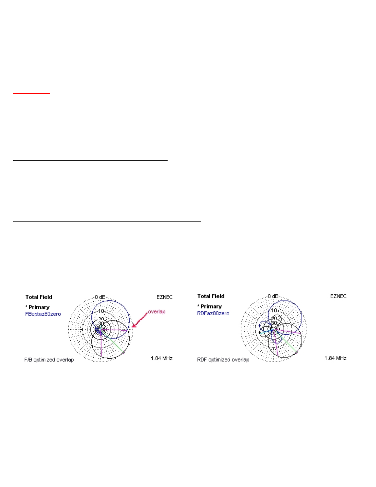
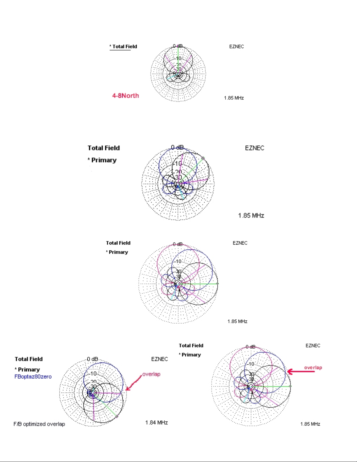
Next are the North and Northeast patterns of the Hi-Z 4-8 overlapped.
Next is the plot three directions of the Hi-Z 4-8PRO overlapped (N, NE & E).
Compare the attenuation at the overlap of the 4 element to 8 element desi n. At the 8 overlap points the attenuation
is ~1db. Therefore, ainin >3db at the overlap points, not to mention the 8 direction control.
Hi-Z 4-8PRO UP Manual V1.0 ©2011 Hi-Z Antennas™ www.hizantennas.c m

4
4 Element overlap pattern Hi-Z 4-8PRO overlap pattern
aterial That the Customer Supplies -
1. Additi nal c ntr l wire f r CTRL3 c nnecti n (if using a 4 c nduct r cable, the GND c nnecti n can be used g ing
thr ugh the RG6 feed c ax shield, freeing up ne c ntr l wire f r CTRL3 c nnecti n).
2. 4 m re verticals exactly like (same height as) r use ur verticals, l k at
http://www.hizantennas.c m/hiz_verticals.htm
3. 4 m re sh rt gr und r ds. Depending n s il type, in the range f 2 –3 feet l ng.
4. RG6 c ax and c nnect rs (c nnecting the 4 extra verticals t the phase c ntr ller and these f r new runs MUST be the
same length as the currently installed runs).
5. Make 8 m re 9-10” l ng wires. Wire size can be made fr m 18 – 20 gauge wire. Terminate each end with #6 ring
terminals. Rec mmend that after the terminals are crimped, that these terminals are s ldered f r reliability. F r Hi-Z
Amp terminati ns. These are t c nnect the 4 new Hi-Z Amps t the new verticals.
6. Weatherproofing the electronics. Y u will need an adequate c ver r encl sure that will keep rain and sn w ff the
phase c ntr ller, in-line pre-amp and filters if installed, and the Hi-Z Amps at the base f each vertical. Water getting
inside f these encl sures WILL cause DAMAGE.
OPT ONS
Filters for site specific issues, for example local and or high power AM broadcast stations. Hi-Z Antennas™ makes a BPF look
at http://www.hizantennas.com/band_pass.htm and a HPF look at http://www.hizantennas.com/high_pass.htm
S TE PREPARAT ON
Place the verticals as far away fr m metallic structures r ther t wers and antennas as p ssible, especially res nant antennas.
The farther the better. Keep away fr m field fencing at least 10 feet. Keep the verticals m re than 5 feet fr m trees and heavy
vegetati n.
Control Cable and Coax Considerations
1. Rec mmended RG6 F c nnect r tightening pr cess. See appendix A.
2. C nduct r wire gauge selecti n is a functi n f the length f the c ntr l cable. 18 gauge wires are adequate ut t 500
feet. Any l nger will need t increase wire gauge size t acc mm date the v ltage dr p ver the run f cable length.
An inexpensive s urce f cable is fr m L wes, H me Dep t, etc in their electrical department. They have 5, 7, 9
c nduct r, 18 gauge direct burial sprinkler c ntr l cable. Usually they will have it n large sp ls and can be cut t the
length y u require. Always get extra.
3. Make sure that the RG6 c nnect rs are tight and f g d quality.
4. If y u crimp n terminals n the c ntr l cable, g the extra step and s lder each terminal f r reliability.
Vertical Placement and nstallation of the Hi-Z Amplifiers
1. Determine where the array (verticals) will be m unted.
2. The verticals need t be as far away as p ssible fr m ther antennas, t wer and ther metallic structures. Especially if
the ther antennas are res nant, this will l wer perf rmance.
3. L cate the gr und r ds cl se t the base f each vertical.
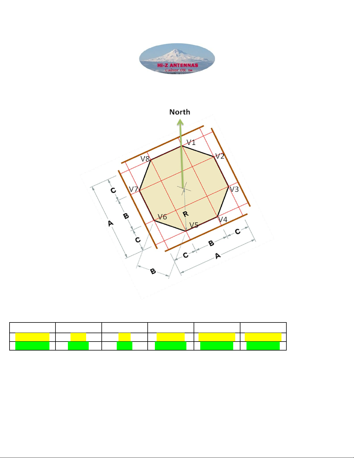
4. Determine the directi n rientati n. Y u have 8 directi ns. S rientati n f the verticals is critical t achieving the
directi nal perf rmance y u require and can be different in l cati ns ar und the w rld. In the case f the Hi-Z 8PRO
the new verticals will g in-between the existing verticals. N w there will be ne vertical every 45 degrees. Typically
Vertical 1 is riented t N rth, Vertical 2 t NE thr ugh Vertical 8 at NW and s n in a CW fashi n.
5. See the diagram n the last page. This will assist y u in laying ut the accurate placement f y ur f ur added verticals.
Hi-Z 4-8PRO UP Manual V1.0 ©2011 Hi-Z Antennas™ www.hizantennas.c m
5
6. Add the extra c ntr l line f r CTRL3 ( r use the RG6 shield in the feed c ax) l ng en ugh t get fr m the shack switch
t the phase c ntr ller.
7. Y u will need a length f RG6 c ax ab ut the same length t c nnect the utput f the in-line pre-amp (at the phase
c ntr ller) t y ur receiver p rt thr ugh the Hi-Z 75 t 50Ω transf rmer.
8. Typically the Hi-Z 4-8 phase c ntr ller and Hi-Z 4-8PRO PnP c ntr ller are l cated in the center f the array. That is n t
necessary. H wever, where these tw c ntr llers are l cated the 8 RG6 c axes fr m the Hi-Z 4-8PRO PnP c ntr ller t
the base f each vertical MUST be cut and terminated t the same length.
9. M unt the additi nal 4 verticals (either h mebrew r Hi-Z verticals).
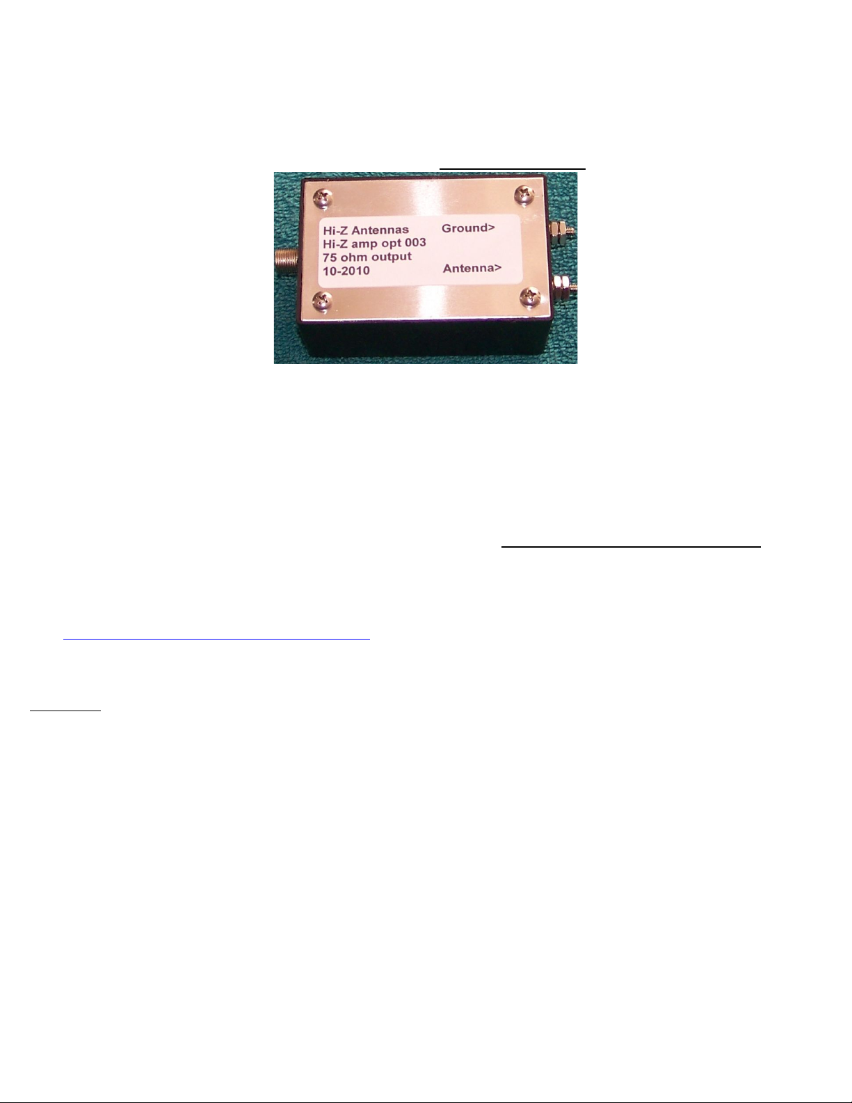
10. M unt the Hi-Z Amplifiers at the base f each vertical. C nnect ne wire fr m the Antenna terminal t the base f the
vertical. C nnect an ther wire fr m the Gr und terminal t the gr und r d. See Hi-Z Amplifier.
11. C nnect each RG6 c ax fr m utput f Hi-Z amp t the c rrect Ant 1, 2, 3, 4, 5, 6, 7 and 8 at the PnP c ntr ller.
12. Weatherpr fing the Hi-Z Amp. Place a c ver ver ( r ther such encl sure) the Hi-Z Amp t insure that rain r sn w
d es n t fall n r get trapped with the encl sure. See ur website under vertical f r ideas n weatherpr fing -
http://www.hizantennas.c m/hiz_verticals.htm
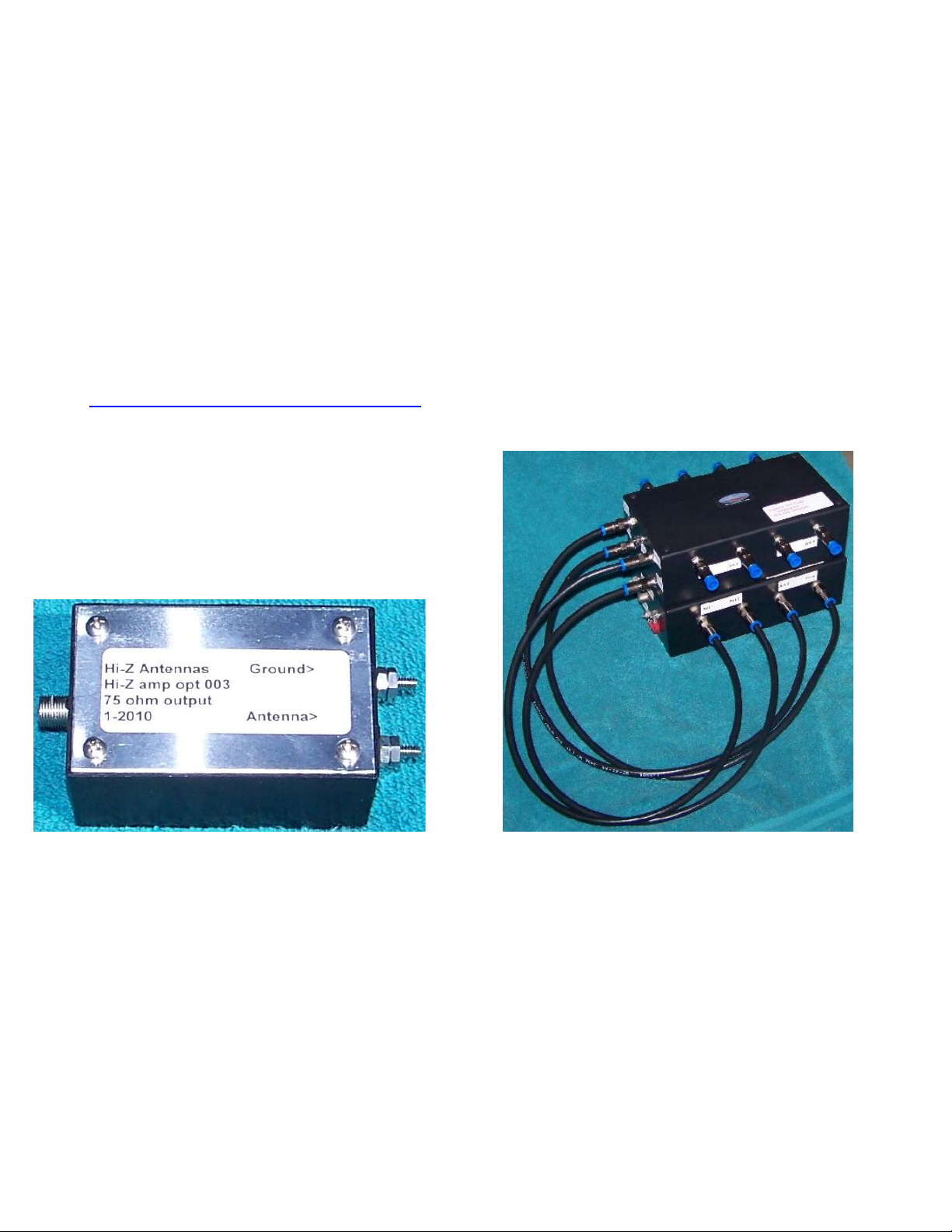
Hi-Z Amplifier Hi-Z 4-8PRO PnP nterface Top/ 4 El. Controller Bottom
The following Block Diagram is a visual aid for the wiring and cabling required to install the Hi-Z 4-
8PRO System.
Hi-Z 4-8PRO UP Manual V1.0 ©2011 Hi-Z Antennas™ www.hizantennas.c m

6
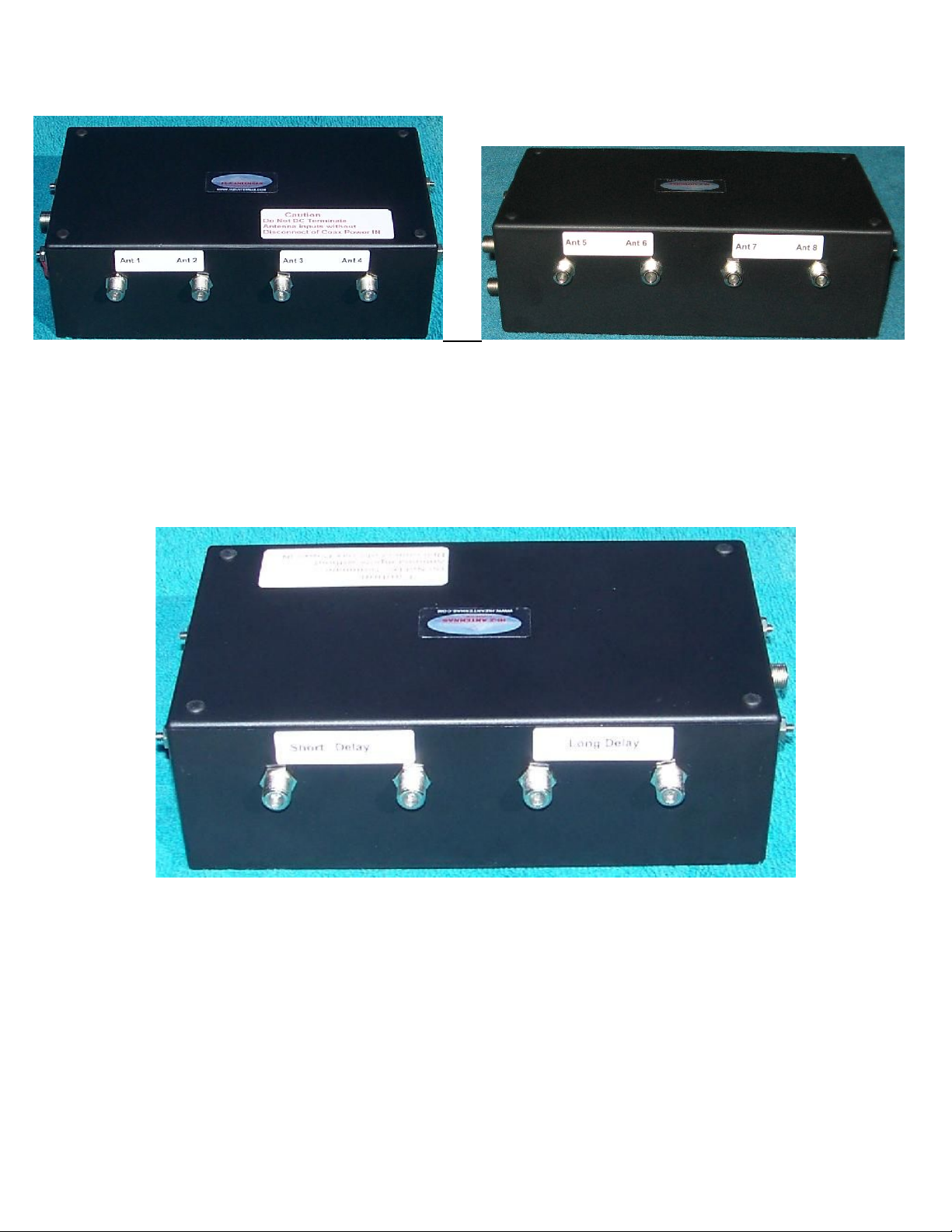
Connecting the Hi-Z 4-8PRO controller to the Hi-Z 4-8PRO PnP Controller
1. Connect the four factory supplied 2 foot long RG6 cables as follows
Hi-Z 4-8PRO phase controller connect
TO
Hi-Z 4-8PRO PnP controller
Ant1 A1 out
Ant2 A2 out
Ant3 A3 out
Ant4 A4 out
See Fig. 2 below See Fig. 1 below
Hi-Z 4-8PRO UP Manual V1.0 ©2011 Hi-Z Antennas™ www.hizantennas.c m

7
Fig.1 Fig.2
C nnect the C ntr l Cable – Ctrl 3 as sh wn in Fig.1.
C nnect ne f each 2 f t jumper wires with terminals t the Gr und and 13.8VDC terminals, see Fig. 3. The ther end n
these wires will terminate t the same labeled terminals n the Hi-Z 4-8PRO phase c ntr ller, see Fig.4.
Fig. 3 Fig. 4
B th c ntr llers will be supplied with a RED jumper c nnected between the 13.8 VDC and C ax P wer In terminals. This
supplies the v ltage t the Hi-Z amps ver the c ax. D n t rem ve this jumper.
Connecting the Verticals and Delay Cable to the Phase Controller
Hi-Z 4-8PRO UP Manual V1.0 ©2011 Hi-Z Antennas™ www.hizantennas.c m
8
Fig. 5 Fig.6
1. Run equal lengths f RG6 fr m the Hi-Z 4-8PRO PnP c ntr ller t each vertical. This c nnects t the Hi-Z 4-8PRO PnP
c ntr ller Ant 1-8 t verticals 1-8. Be certain t bserve these c nnecti ns based n the rientati n r placement f
verticals f r c rrect aiming. Fig. 5 & Fig.6 These cables MUST be the same length as currently installed with the Hi-Z 4.
2. C nnect the Hi-Z supplied sh rt and l ng Delay cables at Sh rt Delay and L ng Delay c nnect rs n the Hi-Z 4-8PRO
phase c ntr ller. Fig.7
Fig. 7
C nnect the fact ry supplied 2 f t wire jumper with f rk terminals fr m either f the 13.8VDC terminals n the c ntr llers
and c nnect the ther end t the 13.8VDC terminal n the75Ω In-line pre-amp.
C nnect the fact ry supplied 2 f t RG6 cable fr m the OUTPUT f the Hi-Z 4-8 phase c ntr ller (Fig.4) t the input c nnect r
n the in-line pre-amp. See Fig. 8
C nnect the 13.8VDC and GND fr m the phase c ntr ller t the PnP c ntr ller (2ft l ng wires, supplied with system).
Hi-Z 4-8PRO UP Manual V1.0 ©2011 Hi-Z Antennas™ www.hizantennas.c m

9
Fig. 8
Connecting the Phase Controller to the Shack Switch and Receiver Fig. 3, 4 & 5
1. C nnect CNTL3 (these are l cated n the Hi-Z PnP c ntr ller) t shack CTRL3 n the switch.
2. Wire the p wer 13.8 VDC and Gr und fr m shack switch t either f the c ntr llers.Fig.9
3. OPTIONS. If a HPF r BPF filter was purchased r cust mer supplied, the filter MUST be inserted between the
c ntr ller utput and bef re the inline preamp (best IMD).
4. C nnect feed RG6 t the utput f the in-line pre-amp t the Hi-Z 75 t 50Ω transf rmer in the shack and the ther
end f the transf rmer c nnects t the RX input.
5. Use y ur existing p wer cable at the existing Hi-Z 4 shack switch f r y ur new 8 directi n shack switch.
Fig. 9
Shack Preparation and Basic Operation
1. L cate the placement f the shack switch.
2. Verify the v ltage level is in the 13.8 VDC area. Depending n the length f the c ntr l cable this v ltage may need t
be adjusted upwards t c mpensate f r any v ltage dr p.
3. Directi n c ntr l. Typically; P siti n 1 = N, 2= NE, 3 = E, 4 = SE, 5 = S, 6 = SW, 7 = W and 8 = NW.
Power Up and System Checks
1. Turn p wer n at the shack switch. One yell w directi n LED sh uld be ON. R tate the directi n r tary switch and
verify that all 8 LEDs sequence c rrectly.
2. Measure the v ltage at the phase c ntr ller. 13.8VDC is ideal. V ltage must be >=12.0 VDC.
Hi-Z 4-8PRO UP Manual V1.0 ©2011 Hi-Z Antennas™ www.hizantennas.c m

10
3. Check the RED LEDs at the Hi-Z Amps at the base f each vertical, they sh uld ALL be ON.
4. Tune t 160 r 80 meters. Switch On and Off the p wer at the Hi-Z shack switch and y u sh uld hear the n ise fl r
increase when switched ON. If able, c mpare t existing antennas, the n ise fl r n the Hi-Z system will likely be
much l wer.
5. Test the directivity by tuning the AM br adcast band ab ve 1 MHz (with n HPF r BPF filter installed). When p inted
at a stati n and the signal is peaked, turn the c ntr l t ther directi ns and bserve the F/B and F/S.
6. On the air, especially l w angle DX, y u will bserve best perf rmance in terms f pattern. When a signal is peaked in
ne directi n, try switching in the directi n either side y u will see the signal decrease c nsiderably. As y u c ntinue
t turn the directi n c ntr l and bserving the signal level, the F/S and F/B perf rmance will bec me apparent.
7. The advantage is the S/N that ur system pr duces. G d DX’ing.
TROUBESHOOT NG also see http://www.hizantennas.com/hiz_faq.htm
Symptom:
Spurs every 10 KHz across 160 meters. Check the Hi-Z Amp c nnecti ns ne f the Hi-Z Amp has the tw wires (Antenna,
Gr und) reversed, verify these c nnecti ns are wired c rrectly.
S me switching p wer supplies can cause this sympt m.
Measure the DC v ltage n the vertical. Fr m gr und t the vertical with a DVM y u sh uld measure ~4 v lts VDC. Impr per
v ltage readings indicate wiring pr blem.
Low MD. Verify that the v ltage at the +13.8VDC and Gr und terminals at the phase c ntr ller measures >=12.0 VDC.
S metimes due t c ntr l cable lengths ne may need t c nsider a separate adjustable v ltage p wer supply t insure
c rrect perati n v ltage f r the Hi-Z system.
Hi-Z Amps – No RED LED ON
Verify that there is a jumper n the phase c ntr ller between the 13.8 VDC and C ax P wer In terminals.
Birdies, Heterodyning
Causes include cl se pr ximity t br adcast stati ns.
S luti ns: One the s urce f this pr blem is l cated, the inserti n f either a Hi-Z BPF r Hi-Z HPF, depending n the s urce f
interference, sh uld be inserted between the utput f the phase c ntr ller and the input t the 75Ω in-line pre-amp.
Directions Seem Wrong
Verify that y u c nnected vertical 1 t c ntr ller Ant1, vertical 2 t c ntr ller Ant 2 and s n.
F r ther t pics see technical & applicati n n tes at http://www.hizantennas.c m/applicati n_n tes.htm
HIGH PERFORMANCE
Hi-Z 4-8PRO UP Manual V1.0 ©2011 Hi-Z Antennas™ www.hizantennas.c m
11
HF RECEIVING SYSTEMS & COMPONENTS
Hi-Z Antennas™ Hi-Z Amplifier
Hi-Z Amplifier
The Hi-Z Amplifier was designed t pr vide amplificati n and matching between the sh rt verticals and the phase c ntr ller in
the Hi-Z phased array c ntr l systems. This amplifier is used n ALL Hi-Z phased array pr ducts. The amp is l cated at the base
f each sh rt vertical. The c nnecting wires must be sh rt, in the range r 8-10 inches l ng. When dressing r r uting the wires
between the vertical and gr und r d t the Hi-Z Amps, maintain as much separati n between the gr und and antenna wires as
p ssible. If these wires are t cl se it will degrade the system perf rmance. The Hi-Z Amp MUST be Weatherproofed!!
Please review ur applicati n and technical n tes t gain ideas f r m unting the Hi-Z amplifiers near the base f the verticals.
See: http://www.hizantennas.com/hiz_verticals.htm
Features:
•Relay input (lightning and static protection, when power is off)
•Easy connections to the base of the vertical and ground
Hi-Z 4-8PRO UP Manual V1.0 ©2011 Hi-Z Antennas™ www.hizantennas.c m

12
Terminals to Ground and Vertical Hi-Z Amp RG6 Output
THANK YOU for selecting Hi-Z Antennas™.
Hi-Z Antennas™
8125 SW Larch Drive
Culver, OR 97734
USA
Vertical Orientation
Hi-Z 4-8PRO UP Manual V1.0 ©2011 Hi-Z Antennas™ www.hizantennas.c m

13
Hi-Z 4-8PRO UP Manual V1.0 ©2011 Hi-Z Antennas™ www.hizantennas.c m
14
8 Circle Array Layout of Verticals
V1 – V8 = Verticals 1-8. Each vertical is 45 degrees spacing.
MODEL Diameter Radius A B C
Hi-Z 4-8PRO 113 * 56.5 104’ 4 ¾” 43’ 2 15/16” 30’ 6 15/16”
Hi-Z 4-8PRO 84.5 ** 42.25 78’ 13/16” 32’ 4 1/16” 22’ 10 3/8”
NOTE: All measurements are r unded t the nearest 1/16”.
* Based n Hi-Z 4 80 f t square f tprint.
** Based n Hi-Z 4 60 f t square f tprint.
All c axes fr m c ntr ller t the vertical are equal length (Radius + 4 feet).
APPEND X A
Hi-Z 4-8PRO UP Manual V1.0 ©2011 Hi-Z Antennas™ www.hizantennas.c m

15
F connector tightening procedure. Placing a 7/16” wrench n the chassis c nnect r while h lding it tight, place
an ther 7/16” wrench ver the Male c nnect r h using and tighten until snug. D n t ver tighten this F c nnect r.
View pictures bel w.
Hi-Z 4-8PRO UP Manual V1.0 ©2011 Hi-Z Antennas™ www.hizantennas.c m
Table of contents
Other Hi-Z Antennas Antenna manuals


Popular Antenna manuals by other brands


Mohu
Mohu AirWave quick start

Vivanco
Vivanco TVA 3030 operating instructions

Megasat
Megasat Caravanman 65 Premium user manual

M2 Antenna Systems
M2 Antenna Systems 303CP26 quick start guide

Electro-Metrics
Electro-Metrics SHL-30 instruction manual

TERK Technologies
TERK Technologies TIAD6M QSG 03 quick start guide


