Hi-Z Antennas HIZ-PC-4A User manual

High Performance HF Receiving array Systems
And Components
HIZ-PC4A-ManualR4.PDF
Stock Number HIZ-PC-4A
Designed for 160 meters through 40 meters and useful at 30 meters and above.
*This All-New Phase Controller is the Heart of the Hi-Z 4 Element receiving Array.
This phasing system allows the selection of 4 different receiving directions when used
in combination with shortened vertical antennas and other Hi-Z subsystems.
This controller is an all-new design providing a new level of previously unobtainable
accuracy. The improved accuracy ensures equal patterns and virtually identical RDF
for all receiving directions.

The Hi-Z Antennas™ HIZ-PC-4A is a signal phasing system that combines the received signals from 4
different shortened vertical elements placed in a square making a phased array.
This phased array produces a narrow pattern selectable in 4 different directions while allowing 12 dB
maximum of RDF (Relative Directivity Factor) and up to 30 dB of front to back ratio. Actual RDF and front to
back depends on the array layout size, frequency, wave arrival angle, and Delay Cable values.
RDF= Relative Directivity Factor which relates to signal to noise improvement
The receiving elements can be placed at 60 or 80 feet per side
dimension depending on the user’s needs. The elements are placed in a
square configuration. The elements need to maintain their equidistant
symmetry. The array can be directionally offset if necessary. The HIZ-SS2
and HIZ-SS2-Plus Shack Switch controls can accept offset values however
because of the relatively wide pattern an offset would not normally be
required with this array.
All four elements must be mounted at ground level within a few inches.
Mounting on a pedestal is very difficult to make work properly. The elements
can be mounted on sloping ground without serious degradation unless the
slope across the array becomes more than ¼ the height of the verticals.
Most installations only require an element ground rod; however, some may
require some short radials in very poor soil. Radial length approaching
element length should suffice. Eight radials equally arranged should suffice
in most really bad soil cases.
This controller operates from 13.8 Volts DC (+11 to +14) at 300 milliamps or less.
•Power is supplied via the Screw terminals marked +13.8 and GND
•Direction Control is via 2 Screw terminals marked CTRL 1 and CTRL2
•Direction control is achieved through grounding combinations of the CTRL terminals
•Output RF impedance is a nominal 75 ohms for feedline cable impedance matching
•The front view size is 3 3/4 X 6 1/4 inches Depth is 2 1/4 inches including input and output connectors
•The screw connectors are universal stainless-steel screw terminals
•Output, Delay, and Antenna Input connectors are high-quality RG-6 coaxial cable connectors
•Each CTRL switching line is transient protected with an MOV and a reverse diode
•The controller supply voltage is protected against overvoltage by an MOV device
•Internal adjustment by movable header pins for 80- or 60-foot array side dimension
Direction Control
The HIZ-SS2
The HIZ-SS2 or HIZ-SS2-Plus are used depending on the array package selected during purchase. The
switch grounds to less than 1 Volt DC the CTRL lines per the table below. Just like a PTT line grounds to
activate.
The SS2 is manual only and the SS2-Plus offers manual and USB direction control
The switching table for this array
Direction
CTRL 1
CTRL 2
NW
11-14 VDC
11-14 VDC
NE
<1 VDC
11-14 VDC
SE
11-14 VDC
<1 VDC
SW
<1 VDC
<1 VDC

Control wires from the shack to the array need to be 4 wires customer supplied or 5 wires if optional 75
ohm preamp will be switched on and off (75 ohm preamp requires an added relay to work with the SS2 and
SS2-Plus shack switches). One each for Ground and +13.8 Supply that are heavy enough to carry 300
milliamps the full distance your array is from the supply. The other 2 direction control wires for the CTRL lines
carry less current at about 40 milliamp max. Typically 18 gauge direct bury sprinkler wire works well out to
several hundred feet. There are many varieties of wire suitable for this array. Users should think about their
array distance and voltage drop as a result of current flow to ensure voltage at the Phase Controller in the
field is 11 to 14 VDC for proper operation. It is possible to raise the voltage at the shack above 14 VDC as
long as the array only sees 11 to 14 VDC at this phase controller. These arrays are quite compatible with
wireless solutions including the Hi-Z Wireless system for eliminating multiple wires.
Choosing an Array Side Dimension and Delay Cable
Hi-Z formerly recommended 80 feet per side for the best 160-meter band
performance. Due to phase combiner and Hi-Z amp improvements we now
recommend using 60 feet per side where you get exactly the same RDF
performance as an 80-foot spacing. Going to 60 feet per side gets you great
patterns on 40 meters at little to none 160-meter performance loss. We offer the
80 feet per side information for users with previously installed arrays on an 80 feet
per side.
Making array choices for Dimension and Delay values can be considerably complicated.
For the person not wanting to make this decision we offer our “go to”all-purpose dimension
and delay values. Making changes later is can be accomplished using different phase delay
lengths or moving the elements. We offer 60 feet per side array dimension with a 60-degree
(long) and a 30-degree (short) cable at 1.84 MHz as a very good starting point. These result in
the following performance.

The available stock delay cables calibrated pair at 1.84 MHz which provides for wide-
band performance have Part Number HIZ-DL4-60-85 for the 60-foot side dimension and
HIZ-DL4-80-113 for the 80 feet per side dimension.
The following pages shows the performance at 160 meters, 80 meters, and 40 meters
for this array at 60 and 80 feet per side dimension. Also, other delay values are possible
with a customer adjustment procedure in Appendix C attached to this manual.
From the plots one can conclude that for a given array dimension the performance degrades
as the frequency goes up. This leaves one with decisions to make if the user’s preferences of
Front to back ratio or RDF (Relative Directivity Factor) are different than our recommended
array. IMPORTANT NOTE
The HIZ-PC4 phase controller has a set of internal header pin jumpers that can be moved to
select an 80 foot per side or a 60 foot per side array. Making this selection insures the best
performance for either array size. The HIZ-PC4 is shipped from the factory with these jumpers
set for the 60 foot per side array. See Appendix D for instructions on changing the header pin
jumpers.
See Appendix D for a
Larger picture of the
Jumper selection.
The following next pages of plots should help in optimizing the array to your individual needs
assuming you desire something other than the recommended 60-foot side dimension. One
must keep in mind that at the higher frequencies you receive there can be varying incoming
signal arrival angles. This can greatly affect the observed front to back ratio. In addition, large
metal objects like metal fencing, metal buildings, or other antennas can also affect patterns
and performance.

60 Foot per Side.One pair of delay cables of 60 degrees for long delay cable and 30
degrees for short delay cable at 1.84 MHz
These delay values are our normal factory recommendation with cables available.
Part Number HIZ-DL4-60-85. In our opinion best all-around performance for 60 feet per side.
60 Foot per Side. One customer adjusted pair of delay cables of 70 degrees for the
long delay cable and 35 degrees for the short delay cable at 1.84 MHz (Max Front to Back
mode) with customer modified delay cables.

60 Foot per Side. One customer adjusted pair of delay cables of 40 degrees for the
long delay cable and 20 degrees for the short delay at 1.84 MHz (Max RDF mode) with
customer modified delay cables.
Good RDF with large side lobes
80 Foot per Side.One pair of delay cables of 80 degrees for the long delay cable and
40 degrees for the short delay cable at 1.84 MHz
These delay values are our normal factory recommendation with cables available.
Part Number HIZ-DL4-80-113. In our opinion best all-around performance for 80 feet per side.
Almost Unusable at 7 MHz

80 Foot per Side. One customer adjusted pair of delay cables of 90 degrees for the
long delay cable and 45 degrees for the short delay cable at 1.84 MHz (Max Front to back
ratio) with customer modified delay cables.
Unusable at 7.2 MHz
80 Foot per Side. One customer adjusted pair of delay cables of 50 degrees for the
long delay cable and 25 degrees for the short delay cable at 1.84 MHz (Max RDF mode) with
customer modified delay cables.
Large side lobes with highest 160 M RDF available on 160 meters

In general, it can be said that higher frequency (40 meters and above) arrays must use the
smaller spacing to maintain good RDF and acceptable pattern. Also, in general it can be said
that the RDF is greater when the Eznec front to side lobe ratio nears -13 dB which is a really
noticeable ratio. It can also be said that as the array size gets smaller the array output level
decreases. All these plots assume no adverse effects from physical real estate issues
dictating array size or objects close to the array.
It is our recommendation to use the recommended 60 foot side dimension with a 60 degree
long delay and 30 degree short delay cable or the 80 foot side dimension with the 80 degree
long delay cable and 40 degree short delay cable.
To PLAN and Build the complete HIZ-4A 4-square array please refer to the Four Element
Square Array Purchasing and Assembly Document located on the www.hizantennas.com
website here or by e-mail request at contact@hizantennas.com
. 60 foot per side 60,30 Phase cables 80 foot per side 80,40 Phase cables
Very similar patterns at 160 Meters with 60 or 80 foot side dimensions.
THANK YOU for selecting Hi-Z Antennas™.
Hi-Z Service Department
We do maintain a service area where we try to provide very rapid turn around of repairs. Typically we
can return repaired equipment within a few business days. Our GOAL is to keep your array uptime
maximized. All repairs are returned as designed and thoroughly tested to meet our advanced internal
specifications.
More information is available at
www.hizantennas.com or e-mail contact@hizantennas.com
Hi-Z Antennas™
8125 SW Larch Drive
Culver, OR 97734 USA
www.hizantennas.com

HIGH PERFORMANCE HF RECEIVING SYSTEMS & COMPONENTS
Appendix A: Element Construction EXAMPLES
Over the years since the Hi-Z Antennas array availability announcement there have been countless
designs of the antenna elements themselves and the necessary mounting type of insulator. As it turns out the
length of the elements are not necessarily critical as long as all elements in an array are the same length and
physical construction. Recommended element length is a minimum 16 feet and a maximum of 24 feet for use
down to the 160-meter band. Arrays with few elements like the three and 4 element arrays can use the shorter
elements while the best 8 element arrays should use the 24-foot elements. This is due to higher combining
losses when combining the higher number of elements.
The mounting insulator requirements have a needed resistance value in excess of 2 Megohms
resistance and very low capacitance to surrounding grounded objects. The suggested size elements present
themselves as a series connected source impedance consisting of a very small capacitance in pico-farads
and a very low radiation resistance. The ground resistance of the needed ground post adds to the radiation
resistance to produce the source resistance value. For best performance the ground resistance of the ground
post used should provide some values less than about 50 ohms.
Typical Source Impedance Calculated Values
Length
inches
Length
Feet
.250 Dia.
.50Dia
.75 Dia
1.0 Dia
.040 wire
Dia
144
12
34pf
38.4pf
41.6pf
44pf
26.1pf
192
16
43.6pf
49pf
52.8pf
55.8pf
33.8pf
216
18
48.4pf
54.2pf
58.3pf
61.6pf
37.7pf
240
20
53.1pf
59.4pf
63.8pf
67.4pf
41.5pf
288
24
62.8pf
69.9pf
75.0pf
79.0pf
49.3pf
Accompanying Radiation Resistance for all these calculations were less than 1 Ohm.
These relatively low values of source capacitance available shape the requirements of the intended
amplifier used to convert the signal from this very high impedance to 75 ohms matching the intended
connecting cables. These low source capacitance values also shape the requirements for the element
mounting insulators. The amplifier input capacitance and the element insulator parallel capacitance both add
together as a load capacitance to the element. As an example, from the chart for 12 feet long 0.25-inch
diameter element the source capacitance is 34 pf. If the combination of the mounting insulator capacitance
and the amplifier input capacitance happened to add up to this 34pf then the available signal to the amplifier
would be ½ half of the open circuit element voltage. That is 6 dB or one S-unit loss due to capacitive division
of the voltage. This division makes the case for keeping insulator capacitance small.
Hi-Z has settled on 16 to 24 feet element length with at least a 7/8 inch OD starting diameter for the
elements. The longer length being our best recommendation. This gives us a source capacitance to work with

of about 75 pf. The older style Hi-Z amplifiers had nearly 20 pf input capacitance. The later Plus-6 versions
were about 18 pf input capacitance. The latest 2020-year versions are about 12pf input capacitance. A
continued improvement. The element insulators over the years started in the very beginning at about 100 pf
which quickly got changed to 20 pf or so. Keeping the insulator capacitance down and the element
capacitance up helps to reduce the affect of minor errors in construction.
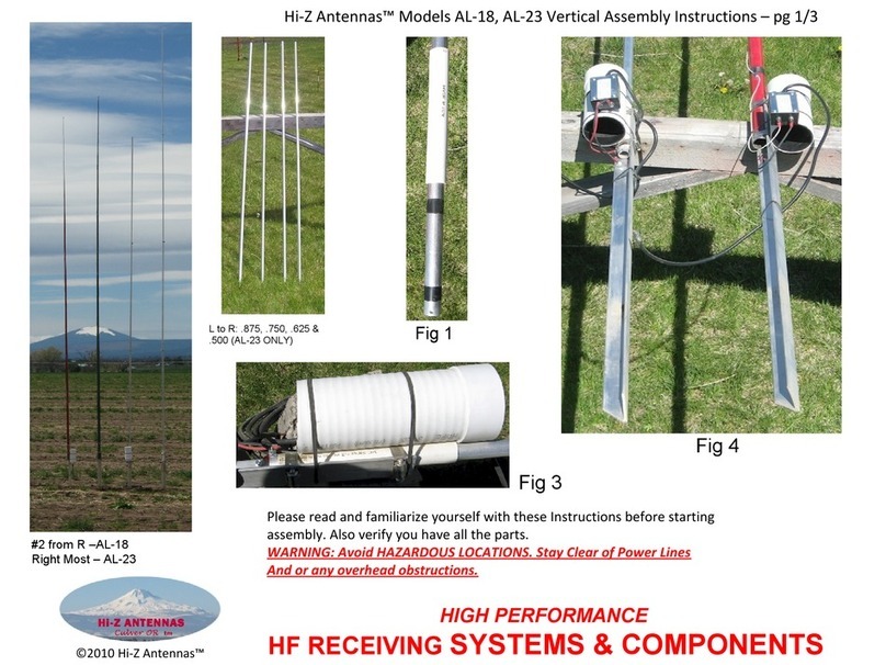
This original picture of the second actual array element built shows how it was offset from the mounting
Tee post to reduce the parallel capacitance. The first element used was clamped right to the Tee post with a
single section of PVC pipe. These offset elements are still being used today in addition to some newer
designs. They started at the bottom with 10 feet of ¾ conduit with a welded junction to a 10 foot piece of ½
inch conduit. The Tee posts came from a farm store and were about 5 feet total length. The Tee post worked
well in fertile soil as a ground connection.
There have been several customers make similar elements as shown in the following pictures. The
elements and insulators have gone through several changes for the better after the following designs.
Aluminum tubing at Hi-Z Antennas was sourced from DX Engineering or Texas Towers.
Hopefully there is enough information following here to allow one to make their own elements or
purchase them from DX Engineering.
Examples follow

In addition here are some early designs by customers. Some were later modified to cover for rain or reduce
height above ground. Elements should NOT be raised above ground by more than a few inches..


This was a pretty successful design but there was another improvement. We began using a ¾ inch OD Fiber
Glass insulator material from McMaster Carr that fit right into the 7/8 inch diameter bottom element

section and a short section of the same tubing to clamp to the mounting angle stock. All these later designs
took advantage of a 3 feet long 1 ½ inch wide piece of aluminum angle stock driven into the ground to serve
as both, the ground connection and the convenient mount for an insulator. The PVC shim added clamping
power to the bottom tubing extension.
This last design was very successful and the end of the element production at Hi-Z Antennas.
The latest year 2020 Hi-Z Amplifiers being in a smaller package can use a smaller diameter and
length rain cover. The Hi-Z Amps V2 are in weather resistant packages but really should have more weather
protection such as a shield or cover. The Amps actually breathe through the RG-6 connector and cable.
DX Engineering now supplies their version of the AL24 Element with their own design. You can find their
product at: WWW.DXENGINEERING.COM and search for AL24
www.hizantennas.com email > contact@hizantennas.com Copyright 6/2020

High Performance HF Receiving array Systems
And Components
Appendix C for the HIZ-PC4A and HIZ-PC8Pro Instruction Manual
Phase Delay Cables for PC4A4 and PC-8Pro Multi Element Arrays
There are two versions of Phase Delay Cables available for both the PC4A 4 element
and the PC-8Pro 8 element versions of Receiving arrays. The same cables are used for
either of the 4 or 8 element arrays.
These are stock number HIZ-DL4A-80-113 and HIZ-DL4A-60-85
These all-new cables are based on the Hi-Z Antennas recommended array side
spacing of 60 feet per side and 80 feet per side for the 4 element versions.
The same cables are used for the Hi-Z Antennas recommended 85 feet and the 113
feet diameter 8 element versions. Proper selection of which cable is determined by
reading the Hi-Z 4 element or Hi-Z 8Pro manual which shows performance and
receiving patterns depending on phase delay values.
Remove and Discard Double Female Splice
This picture shows how we ship the delay cables. There are the two cables rolled together
with the LONG delay cable on the inside and the SHORT delay cable on the outside.
These cables are spliced together with a very cheap F connector splice. Do yourself a
favor and throw it away when you unwrap the Short delay cable. Trust us, you will have
trouble with that splice if you try to use it to carry signals.

The cables as we supply them are listed in the table below. The lengths may change a
small amount if the cable vendor supplies us with a changed Velocity factor for the cable.
4 element 80 feet
4 element 60 feet
8Pro 113 feet
8Pro 85 feet
100.5 feet/50.25 feet
75 feet/37.5 feet
100.5 feet/50.25 feet
75feet/37.5 feet
80 and 40 degrees
60 and 30 degrees
80 and 40 degrees
60 and 30 degrees
It is very important that the short delay cable remains ½ the physical length of the Long
delay cable in the case of use alternate phase delays.
Custom Delay cables
In order to make custom cables one can use our values from the table above. We have
established that 100.5 feet will equal an 80 degree phase shift at 1.840MHz using precision
equipment. Take 100.5 divided by 80 degrees and you get a feet per degree answer which is
the key value. 100.5/80= 1.256 feet of RG-6 per degree of phase shift.
From this key value you can calculate any value of phase delay cable length.
For instance, the MAX RDF delay values needed for an 80 foot 4 element array can be
calculated by referring to the needed phase delay from the 4 element manual.
The values are 50 and 25 degrees are taken from the manual. All we need in this case is to
multiply our key of 1.256 feet per degree times the 50 degrees needed.
1.256 * 50= 62.8 feet of Rg-6 cable. As stated above the short delay would ½ of that value
at 62.8 / 2 or 31.4 feet of cable. The cables would be 62.8 feet and 31.4 feet.
A second example would be the 60 foot per side 4-square which shows in the 4 element
manual a needed 70 and 35 degree set of cables for side maximum front to back.
Again, our key of 1.256 * 70 degrees= 87.9 feet for the long delay and 87.9 / 2 or 44 feet for
the short cable.
Rounding cable length values to the nearest 0.1 foot value is very sufficient when 1.256 feet
equal 1 degree of phase shift. At 1840 KHz one wavelength = 534.55 feet. Dividing this by
360 degrees gives 1.485 feet per degree. Our measurement of 1.256 feet per degree divided
by the 1.485 feet per degree gives a Vp or velocity of propagation in the coax of .846 .
Factory cables can be used with short cables adding to the length by using good quality type
F barrel connectors. This image shows good and bad barrel connector choices.

High Performance HF Receiving array Systems
And Components
Appendix D for the HIZ-PC4A Manual
There are 4 sets of two pin jumpers on the PC4A circuit board to adjust the array for one of two array
size selections.
There is a 60 foot per side and an 80 foot per side recommended size selection for best
performance of these arrays.
You must remove the tiny screws holding the lid on the PC4-A phase combiner to access these
pins. Opening the enclosure will reveal the circuit board as pictured.
Each little pair of jumpers can be moved from factory setting of 60 foot dimension at the right side to
80 foot settings to the left. Each jumper must remain inline with the relays as seen at the top of the
board. It may be pertinent to draw a simple sketch of the pin positions before attempting to move the
jumpers if the user is not familiar with
these type pin header connectors. All 4 pairs must be moved at the same time in order for the array to
work properly.

Each little pair of jumpers can be moved from factory setting of 60 foot dimension at the right side to
80 foot settings to the left. Each jumper must remain inline with the relays as seen at the top of the
board. It may be pertinent to draw a simple sketch of the pin positions before attempting to move the
jumpers if the user is not familiar with these type pin header connectors. All 4 pairs must be moved at
the same time in order for the array to work properly.
More information is available at
www.hizantennas.com or e-mail contact@hizantennas.com
Hi-Z Antennas™
8125 SW Larch Drive
Culver, OR 97734 USA
www.hizantennas.com
Table of contents
Other Hi-Z Antennas Antenna manuals
Popular Antenna manuals by other brands
Harris
Harris NEO GPS-3903 Safety instructions and regulator compliance manual

Teleco
Teleco VoyagerG3 65 Installation guide and user's manual

Wilson Electronics
Wilson Electronics 301133 installation guide
![Panorama Antennas LP[G]AM Series installation instructions Panorama Antennas LP[G]AM Series installation instructions](/data/manuals/ng/4/ng4l/sources/panorama-antennas-lp-g-am-series-manual.jpg)
Panorama Antennas
Panorama Antennas LP[G]AM Series installation instructions
Proxicast
Proxicast ANT-121-M22 manual
Sennheiser
Sennheiser AC 3 instruction manual

Megasat
Megasat Satmaster Portable User manual and installation instructions
Gotting
Gotting HG G-98780-A Device description

MFJ
MFJ Octopus Antenna MFJ-2100 instruction manual
Shure
Shure PA421A instructions
Chameleon Antenna
Chameleon Antenna EMCOMM III Operator's manual

MFJ
MFJ MFJ-1886TR instruction manual

