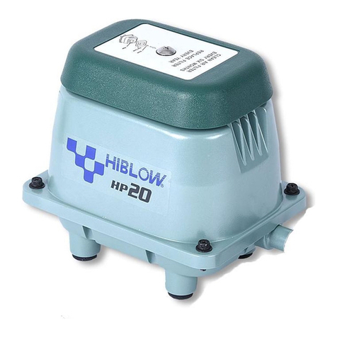
HIBLOW HP Series User manual

1
HP-100/120
HP
HP Series
STRUCTURE AND PART NAMES
HP-100/120
HP-100
HP-120
1997/10
1997/10
─
─
HP-100/120
漓 FilterCover
滷 SemiCoverPacking
澆 Filter
潺 FittingBoss
潸 UpperHousing
澁
SoundAbsorber(Lap)
澀 CasingBlockA
潯
ValveChamberpacking
潛 CasingBlockB
濳 Valve
潭 DiaphragmRing
澂 Diaphragm
潼 DiaphragmBase
潘 FrameCover
澎 SPSwitch
澑
Safetypin+Lockingcollar
濂 Electromagnet
潦 ActuatingRod
澳 L-Tube
澣 HoseBand
澡 Frame
澤
VibrationControlRubber
澹 CenterPlate
濆 Gasket
澪
SoundAbsorber(Filter)
濟 LowerHousing
濕 PowerCord
Air pump Start of production
Discontinuance of production

2
HP
ReplacingtheChamberBlock
●
Besuretounplugthepumpunit.
●
Replacethediaphragmsandthevalveswithnewonesatleastonceayeartooneanda
halfyearregularlyinordertomaintaintheirinitialperformance.
●
Forchamberblockreplacement,besuretochangebothchamberblocksatthesametime.
●
Therodemployspowerfulpermanentmagnets.Therefore,besuretoremoveyourwatch
and any other precision machines before operation as they may be affected by the
strongmagneticforce.
●
Donotputtheactuatingrodclosetoamagneticcard,magneticdiskorothermagnetic
mediaasthedatamaybedestroyed.
STEP
1
STEP
1
Toremovetheupperhousing.
(Referto
REMOVING UPPER HOUSING)
Removethesoundabsorber.
STEP
2
STEP
2
Uudo the frame screws and remove the frame
cover.
STEP
3
STEP
3
PullouttheL-tubefromthecasingblock.
HP-
100
/
120
REPLACING THE CHAMBER BLOCK
CAUTION
!
REMOVAL OF THE CHAMBER BLOCKS

3
ReplacingtheChamberBlock
HP
STEP
4
STEP
4
STEP
5
STEP
5
STEP
6
STEP
6
Removeoneofthediaphragmmountingblocksfrom
the actuating rod and pull out the other diaphragm
mountingblockwiththerod.Afterthat,separatethe
diaphragmmountingblockandtherod.
●Whenpullingouttherod,besurenottocatchtherod
projectionontheleveroftheSPswitch.
●Ifthepumpstopsautomatically,thesafetypinmustbebrokentopreventany
furtherdamagetothepump.Besureallbrokenpiecesareremovedfromthe
unit.(SeeStep15)
Remove the 4 screws holding the chamber block
andthecasingblock.
(4screwsoneachside)
STEP
7
STEP
7
Incaseofreplacingthewholediaphragmmounting
block,movestraighttoSTEP 12.
Removethediaphragmringfromthediaphragm,
and then, detach the diaphragm from the
diaphragmbase.
Remove 1 U-lock nuts from one side holding the
diaphragmmountingblocktotherod.
●Usethenutdrivertoloosen(ortighten)theU-locknut.
HP-
100
/
120
REPLACING THE CHAMBER BLOCK
REPLACING THE DIAPHRAGM

4
HP
ReplacingtheChamberBlock
HP-
100
/
120
REPLACING THE CHAMBER BLOCK
STEP
8
STEP
8
Fit a new diaphragm and diaphragm ring in the
diaphragmbase.
●Besurenottoleaveagapbetweenthem.
STEP
9
STEP
9
In case of replacing the whole diaphragm casing
block,movestraightto
STEP 12
.
SeparatecasingAandcasingB.
RemovethevalvesfromthecasingB.
●If it is difficult to separate them, insert the tip of a
flatbladescrewdriverintotheclearance.
●Pulloutthevalvesastheycanberemovedeasily.
STEP
10
STEP
10
Inserteachnewvalveintothecenterholdofvalve
seat,andsecurethembypullingwithradiopliers.
●When reinstalling the valves, make sure the exhaust
andintakesidesarecorrectlyfitted.
STEP
11
STEP
11
Cut away end of respective valves pulling parts
(justinfrontofthickparts)byscissorsornippers.
REPLACING THE VALVE

5
ReplacingtheChamberBlock
HP
HP-
100
/
120
REPLACING THE CHAMBER BLOCK
STEP
12
STEP
12
STEP
13
STEP
13
STEP
14
STEP
14
Mountthe casingblock withscrews (4screws on
eachside).
AndinsertL-tubeintothenozzleofcasingA.
Then,fixitwithhoseclip.
Completetheothercasingblockinthesameway.
Fittheactuatingrodbyaligningitwiththegroove
andtightenU-locknutandflatwasherbythenut
driver.
●UsenewU-locknutandwasher,otherwise,U-locknut
mayworklooseandcausemalfunction.
Inserttheactuatingrodintothemachinebody.Be
suretofit the positioning boss onthediaphragm
baseintotheconcavepartoftheframestay.
Secure the diaphragm mounting block on the
other side and tighten washers and U-lock nuts
withthenutdriver.
Make sure that gap between the actuating rod
andtheelectromagnetsiseven.
STEP
15
STEP
15
Checkthatthebrokenpinisremovedfromunit.
●Ifthebrokenpinisleftinsidetheunit,itcangetcaught
in between electromagnets and actuating rod, which
cancausebreakdown.
FITTING THE CHAMBER BLOCKS
REPLACEMENT OF SAFETY PIN

6
HP
ReplacingtheChamberBlock
HP-
100
/
120
REPLACING THE CHAMBER BLOCK
STEP
16
STEP
16
Insert a new safety pin through the hole on the
terminalside.
(Please Insert safety pin through the spring
electrode,L-shapedleverinsuchorder.)
STEP
17
STEP
17
Installthelockingcollarfromtheothersideofthe
terminalandinsertituntilitclicks.
STEP
18
STEP
18
This completes the replacement of the safety pin
procedure.
Make sure the gap between L-shaped lever and
taboftheactuatingrodiseven.
●Becarefulnottotouchtheterminalwhenthepoweris
on,testingtheoperatingconditionsasthiswillresultin
anelectricshock.
●Unplugthepumpimmediatelyafterthecheck.
STEP
19
STEP
19
Securetheframecoverwiththescrews.

7
ReplacingtheChamberBlock
HP
HP-
100
/
120
REPLACING THE CHAMBER BLOCK
STEP
20
STEP
20
STEP
21
STEP
21
Installthesoundabsorber.
Placetheupperhousingbackonbody.
●Be extremely careful not to catch the sound absorber
ontheupperhousing.
Fastenitwiththebolts.
Then,placethefilterandfiltercoverontheupper
housing. (Refer to FILTER CLEANING AND
REPLACEMENT)

8
HP
ReplacingtheElectromagnet
HP-
100
/
120
REPLACING THE ELECTROMAGNET
●Besuretounplugthepumpunit.
●Whenperforming replacement work,thepump bodymaystill behotand you could
getburned.Sopleasewaituntilthepumphascooledbeforehandling.
●Be sure to remove the chamber block and the actuating rod before replacing the
electromagnet.
●It is better to let an experienced technician handle the soldering process. Take
precautionsagainstgettingburned.
STEP
1
STEP
1
Cut the wire from the terminals on electromag-
netswithnippers.
●Itisrecommendedthatyoumakeanoteofthewiring.
STEP
2
STEP
2
Loosenthescrew,fixingSPswitchandremoveit.
(There are hexagonal nuts at SP switch side. Be
surenottolosethemastheyfallinsidetheunit.)
STEP
3
STEP
3
Removethenutsbytheboxdriver.
(8mmwrench)
Pullouttheelectromagnetfromthepumpbody.
CAUTION!
REMOVAL OF ELECTROMAGNET

9
ReplacingtheElectromagnet
HP
STEP
4
STEP
4
STEP
5
STEP
5
STEP
6
STEP
6
Insertthewireintothesilicontube,andtieupina
bundle.
Stripthecoatingoffeachwire.
(5-7mmfromtheend)
Connectthewirestotheterminals.
Solderthewirestotheterminals.
Thewirerequiresasolderedconnection.
Mountnewtheelectromagnetsintheunit.
Tightenupnutswithnutdriver.
STEP
7
STEP
7
This completes the electromagnet replacement
procedure.
InstalltheSPswitchtotheframewiththescrews.
●Becarefulofthedirectionofswitchlever.(Refertothe
pictures)
HP-
100
/
120
REPLACING THE ELECTROMAGNET
FITTING THE ELECTROMAGNET
Other manuals for HP Series
3
This manual suits for next models
2
Table of contents
Other HIBLOW Pond Pump manuals
Popular Pond Pump manuals by other brands
Pontec
Pontec PondoTronic UVC 18 operating instructions

Oase
Oase AquaMax Eco Classic 9000 C operating instructions

MDM
MDM 4200VAF12 Installation and service manual

Aquagarden
Aquagarden BIOlogic Gravity 12000 instructions

Atlantic
Atlantic Typhoon TADK1800 product manual

TeichTip
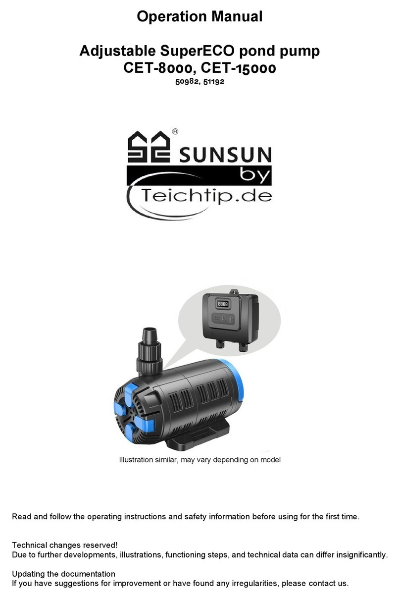
TeichTip SUNSUN Adjustable SuperECO CET-8000 Operation manual