HIBLOW HP Series User manual

1
HP-150/200
HP
HP Series
STRUCTURE AND PART NAMES
HP-150
/
200
Air pump Start of production
Discontinuance of production
HP-150
HP-200
2001/9
2001/9
─
─
HP-150/200
漓 FilterCover
滷 SemiCoverPacking
澆 Filter
潺 FittingBoss
潸 UpperHousing
澁
SoundAbsorber(Lap)
澀 CasingA
潯
ValveChamberPacking
潛 CasingB
濳 Valve
潭 DiaphragmRing
澂 Diaphragm
潼 DiaphragmBase
潘 ActuatingRod
澎 SPSwitch
澑
Safetypin+Lockingcollar
濂 FrameStay
潦 Electromagnet
澳 FrameCover
澣 L-Tube
澡 HoseBand
澤
VibrationControlRubber
澹 CenterPlate
濆 Gasket
澪
SoundAbsorber(Filter)
濟 LowerHousing
濕 PowerCord
2
HP
ReplacingtheChamberBlock
HP-
150
/
200
REPLACING THE CHAMBER BLOCK
CAUTION!
●
Besuretounplugthepumpunit.
●
Replacethediaphragmsandthevalveswithnewonesatleastonceayeartooneand
ahalfyearregularlyinordertomaintaintheirinitialperformance.
●
For chamber block replacement, be sure to change both chamber blocks at the same
time.
●
The rod employs powerful permanent magnets. Therefore, be sure to remove your
watchandanyotherprecisionmachinesbeforeoperationastheymaybeaffectedby
thestrongmagneticforce.
●
Donotputtheactuatingrodclosetoamagneticcard,magneticdiskorothermagnetic
mediaasthedatamaybedestroyed.
STEP
1
STEP
1
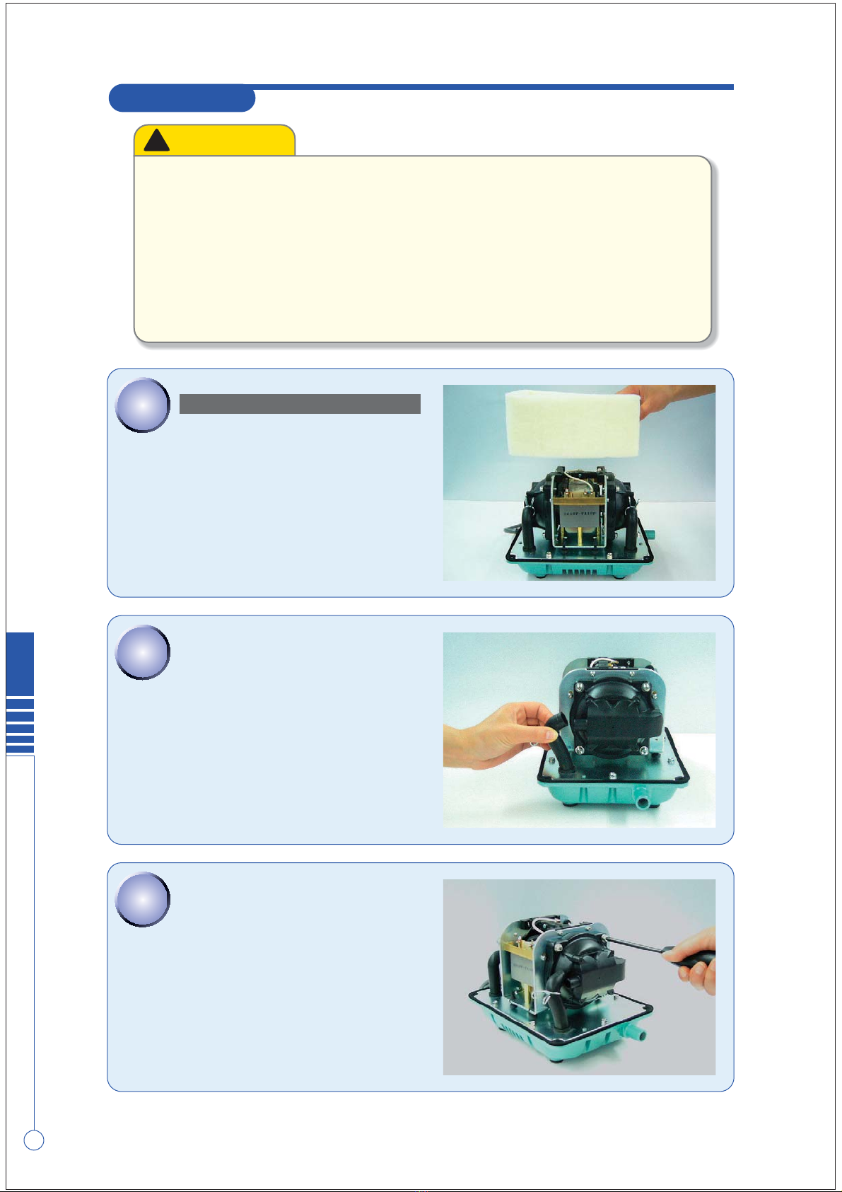
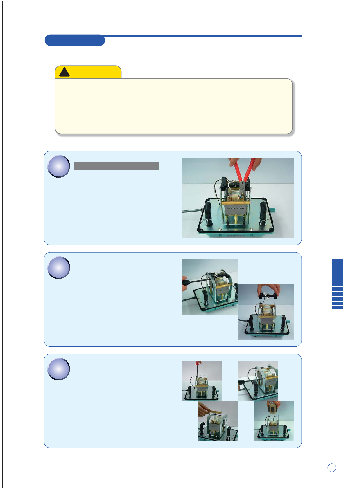
REMOVAL OF THE CHAMBER BLOCKS
Toremovetheupperhousing.
(Referto
REMOVINGUPPERHOUSING
)
Removethesoundabsorber.
STEP
2
STEP
2
PullouttheL-tubefromthecasingblock.
STEP
3
STEP
3
Remove the 4 screws holding the chamber block
andthecasingblock.
(4screwsoneachside)
3
ReplacingtheChamberBlock
HP
HP-
150
/
200
REPLACING THE CHAMBER BLOCK
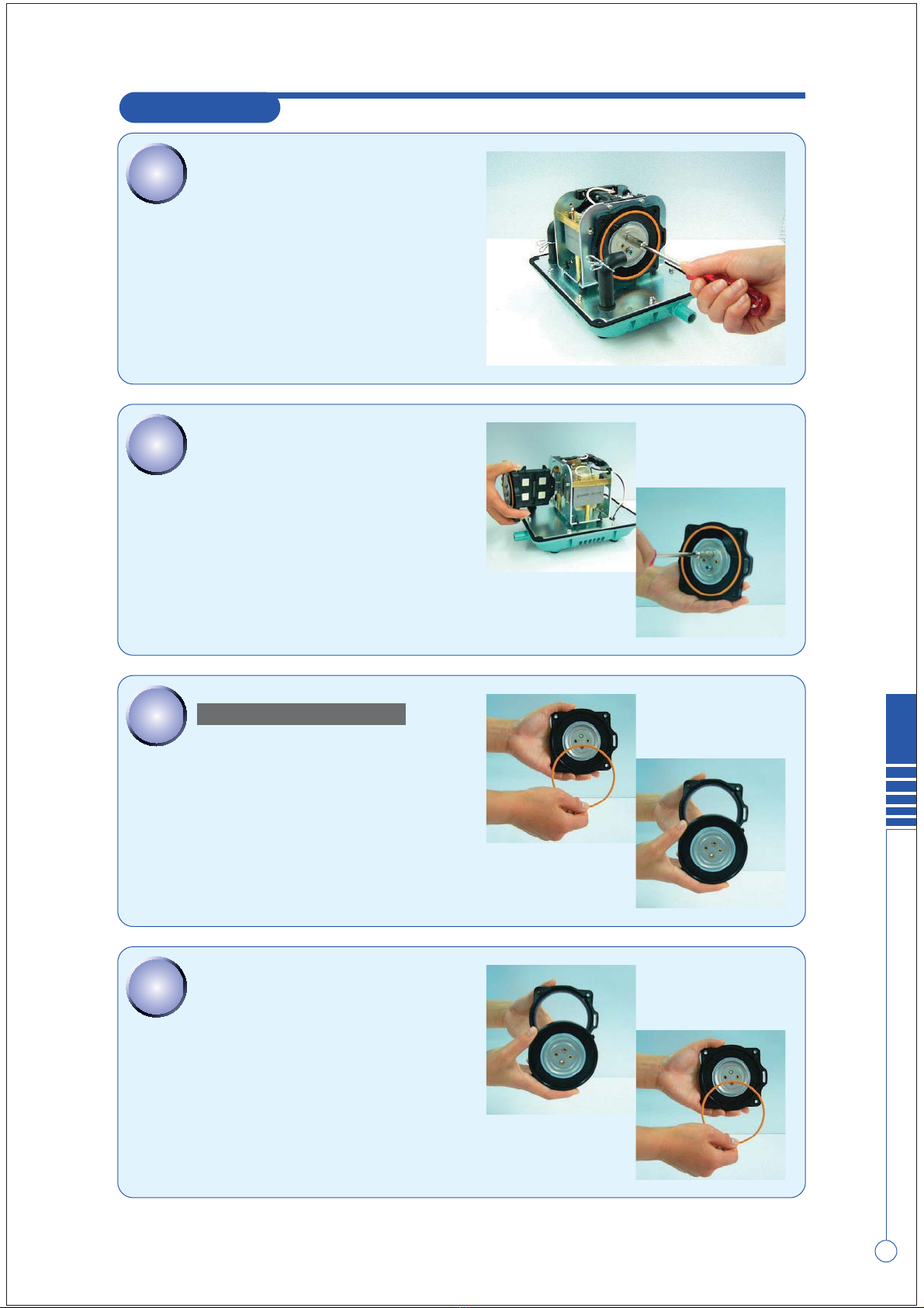
STEP
4
STEP
4
STEP
5
STEP
5
STEP
6
STEP
6
In case of replacing the whole diaphragm
mountingblock,movestraighttoSTEP 11.
Removethediaphragmringfromthediaphragm,
and then, detach the diaphragm from the
diaphragmbase.
REPLACING THE DIAPHRAGM
Remove 2 U-lock nuts from one side holding the
diaphragmmountingblocktotherod.
●
Usethenutdrivertoloosen(ortighten)theU-locknut.
STEP
7
STEP
7
Fit a new diaphragm and diaphragm ring in the
diaphragmbase.
●
Besurenottoleaveagapbetweenthem.
Remove one of the diaphragm mounting blocks
from the actuating rod and pull out the other
diaphragm mounting block with the rod. After
that,separatethediaphragmmountingblockand
therod.
●
Whenpullingouttherod,besurenottocatchtherod
projectionontheleveroftheSPswitch.
●
If the pump stops automatically, the safety pin must be broken to prevent any
furtherdamagetothepump.Besureallbrokenpiecesareremovedfromtheunit.
(SeeStep14)
4
HP
ReplacingtheChamberBlock
HP-
150
/
200
REPLACING THE CHAMBER BLOCK
STEP
8
STEP
8
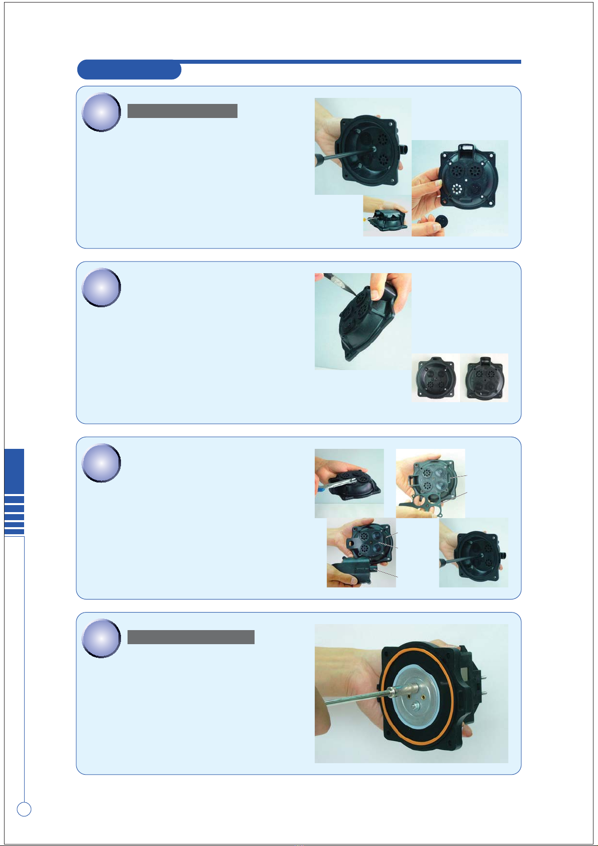
REPLACING THE VALVE
STEP
9
STEP
9
Inserteachnewvalveintothecenterholdofvalve
seat,andsecurethembypullingwithradiopliers.
●
When reinstalling the valves, make sure the exhaust
andintakesidesarecorrectlyfitted.
STEP
10
STEP
10
Cut away end of respective valves pulling parts
(justinfrontofthickparts)byscissorsornippers.
HoldthevalvechamberpackingbetweencasingA
andcasingB.
Then,fixthemwith5screws.
STEP
11
STEP
11
Fittheactuatingrodbyaligningitwiththegroove
andtightenU-locknutandflatwasherbythenut
driver.
●
UsenewU-locknutandwasher,otherwise,U-locknut
mayworklooseandcausemalfunction.
FITTING CHAMBER BLOCKS
In case of replacing the whole diaphragm casing
block,movestraighttoSTEP 11.
separate casing A and casing B, by removing 5
innerscrews.
RemovethevalvesfromcasingB.
●
If it is difficult to separate them, insert the tip of a
flatbladescrewdriverintotheclearance.
●
Pulloutthevalvesastheycanberemovedeasily.
●
Checkifthevalvechamberpackingisbroken.
CasingB
Valve
Chamber
Packing
CasingB
Valve
Chamber
Packing
CasingA

5
ReplacingtheChamberBlock
HP
HP-
150
/
200
REPLACING THE CHAMBER BLOCK
STEP
12
STEP
12
STEP
13
STEP
13
STEP
14
STEP
14
Checkthatthebrokenpinisremovedfromunit.
●
Ifthebrokenpinisleftinsidetheunit,itcangetcaught
in between electromagnets and actuating rod, which
cancausebreakdown.
REPLACEMENT OF SAFETY PIN
Inserttheactuatingrodintothemachinebody.Be
suretofitthepositioningbossonthediaphragm
baseintotheconcavepartoftheframestay.
Secure the diaphragm mounting block on the
other side and tighten washers and U-lock nuts
withthenutdriver.
Make sure that gap between the actuating rod
andtheelectromagnetsiseven.
Mountthecasingblockwithscrews(4screwson
eachside).
And insert L-tube into the nozzle of casing A.
Then,fixitwithhoseclip.
Completetheothercasingblockinthesameway.
STEP
15
STEP
15
Insert a new safety pin through the hole on the
terminalside.
(Please Insert safety pin through the spring
electrode,L-shapedleverinsuchorder.)
6
HP
ReplacingtheChamberBlock
HP-
150
/
200
REPLACING THE CHAMBER BLOCK
STEP
16
STEP
16
Installthelockingcollarfromtheothersideofthe
terminalandinsertituntilitclicks.
STEP
17
STEP
17
Thiscompletes the replacement ofthe safety pin
procedure.
Make sure the gap between L-shaped lever and
taboftheactuatingrodiseven.
●
Becarefulnottotouchtheterminalwhenthepoweris
on,testingtheoperatingconditionsasthiswillresultin
anelectricshock.
●
Unplugthepumpimmediatelyafterthecheck.
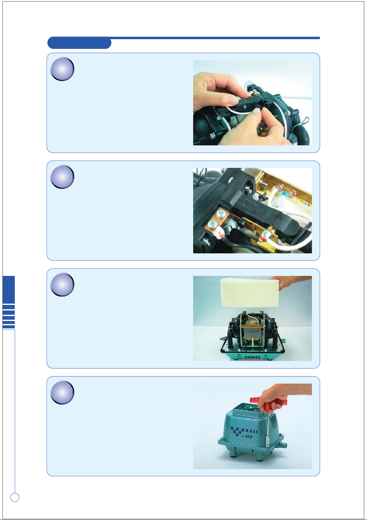
STEP
19
STEP
19
STEP
18
STEP
18
Installthesoundabsorber.
Placetheupperhousingbackonbody.
●
Be extremely careful not to catch the sound absorber
ontheupperhousing.
Fastenitwiththebolts.
Then, place the filter and filter cover on the
upper housing. (Refer to
FILTER CLEANING AND
REPLACEMENT
)
HP-
150
/
200
REPLACING THE ELECTROMAGNET
STEP
1
STEP
1
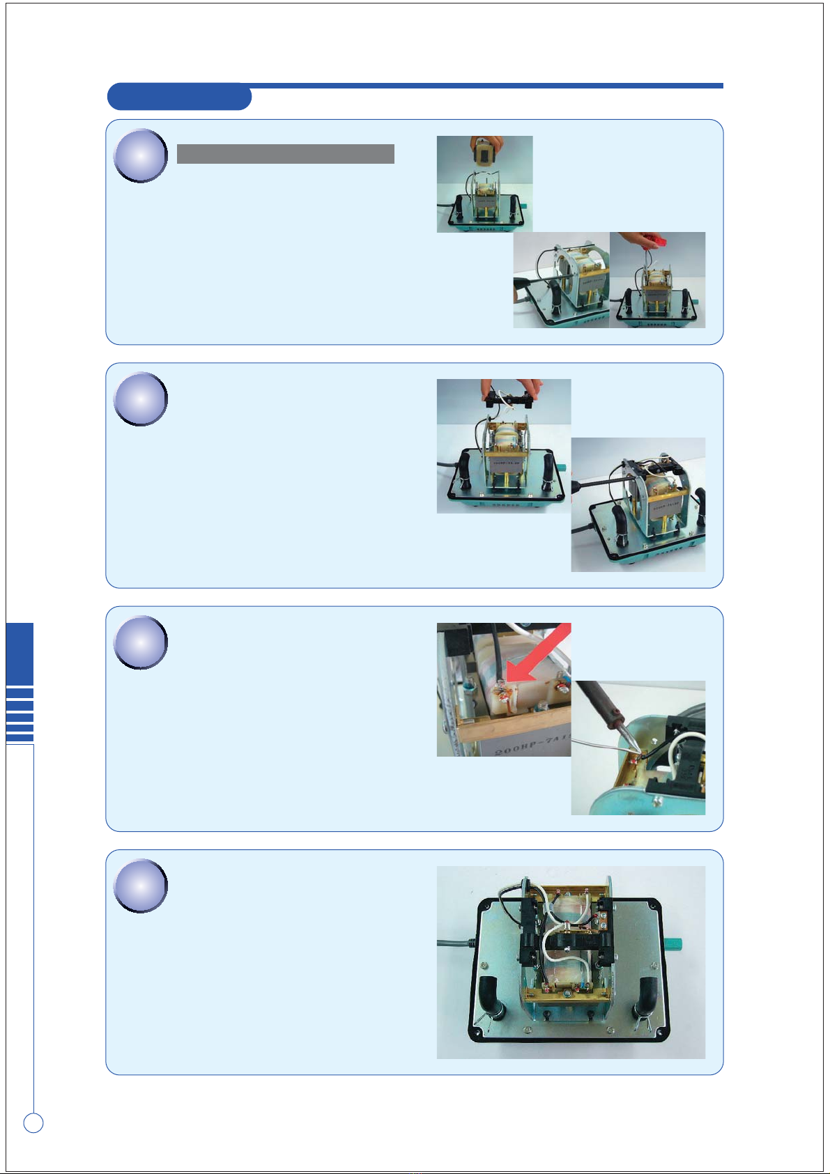
REMOVAL OF ELECTROMAGNET
Cutthewirefromtheterminalsonelectromagnets
withnippers.
●
Itisrecommendedthatyoumakeanoteofthewiring.
STEP
2
STEP
2
Loosenthescrew,fixingSPswitchandremoveit.
(There are hexagonal nuts at SP switch side. Be
surenottolosethemastheyfallinsidetheunit.)
STEP
3
STEP
3
Removethehexagonalnutsbythenutdriver.
(8mmwrench)
Loosen the screw holding the frame stay, and
removeit.
Pullouttheelectromagnetfromthepumpbody.
CAUTION!
●
Besuretounplugthepumpunit.
●
Whenperformingreplacementwork,thepumpbody may still be hot and you could
getburned.Sopleasewaituntilthepumphascooledbeforehandling.
●
Be sure to remove the chamber block and the actuating rod before replacing the
electromagnet.
●
Itisbettertoletanexperiencedtechnicianhandlethesolderingprocess.
Takeprecautionsagainstgettingburned.
7
ReplacingtheElectromagnet
HP
HP-
150
/
200
REPLACING THE ELECTROMAGNET
STEP
5
STEP
5
STEP
4
STEP
4
STEP
6
STEP
6
STEP
7
STEP
7
This completes the electromagnet replacement
procedure.
Insertthewireintothesilicontube,andtieupina
bundle.
Stripthecoatingoffeachwire.
(5-7mmfromtheend)
Connectthewirestotheterminals.
Solderthewirestotheterminals.
Thewirerequiresasolderedconnection.
Mountnewelectromagnetintheunit.
Fixframestaytemporarily.
(Do not tighten screw of frame stay and keep
themratherloose.)
Tightenuphexagonalnutswithnutdriver.
Fastenscrewsofframestay.
MOUNTING THE ELECTROMAGNET
InstalltheSPswitchtotheframewiththescrews.
●
Becarefulofthedirectionofswitchlever.(Refertothe
pictures)
8
HP
ReplacingtheElectromagnet
Other manuals for HP Series
3
This manual suits for next models
2
Table of contents
Other HIBLOW Pond Pump manuals


