Hideaway Concelo CRL160D User manual

FIG.6
FIG.5
Concelo Laundry CRL160D
Installation Instructions
Read all instructions before installing this bin unit.
Failure to install the bin correctly may void warranty.
INSTALLATION VIDEO:
NZ: hideawaybins.co.nz/concelo-laundry-installation
AUS: hideawaybins.com.au/concelo-laundry-installation
Or scan the QR code...
If predrilling using CNC refer to:
NZ: hideawaybins.co.nz/info/downloads
AUS: hideawaybins.com.au/info/downloads
for drilling position CAD les.
WATCH FIRST
New Zealand Australia
HIDEAWAY NEW ZEALAND
HIDEAWAY AUSTRALIA
1800 042 642 / info@hideawaybins.co.nz / hideawaybins.com.au
Step 1 – Unpack carton
• The hamper and associated parts should be put to one side.
• Inner carton 1 contains collar components to be attached to the door panel.
• Inner carton 2 contains runners and mounting brackets to be mounted to the
cabinet carcase.
Step 2 – Mount collar to door panel
• Open Inner Carton 1 and follow the Concelo CRL160D Laundry Collar Assembly
Instructions within.
Step 3 – Mount runners inside cabinet carcase
• Open Inner Carton 2 and follow the Concelo CRL160D Laundry Runner Installation
Instructions within.
Step 4 – Assemble collar and door panel to runners
• Position collar assembly as shown in Fig 4. TIP: Ensure that runners are pulled
forward, there is a black tab at the front of the runner that can be pulled while
holding the door panel.
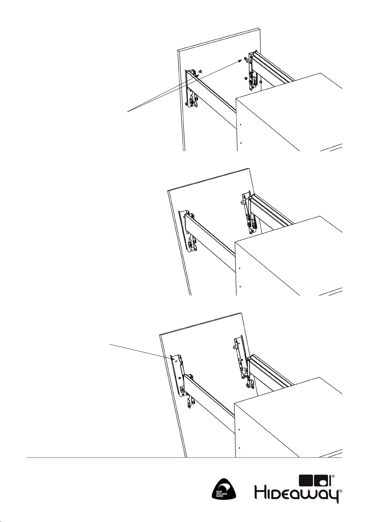
Step 5 – Adjust the door panel position (Fig 5)
• Loosen the 6 door bracket bolts using the 4mm Hex key provided.
• Adjust the door to be square and parallel to carcase and in the correct vertical
position using the adjustment cams.
• Tighten the 6 door bracket bolts.
• Loosen the 6 door mounting screws and adjust the horizontal position of the
door panel.
• Tighten the 6 door mounting screws.
Step 6 – Fit the door bracket covers (Fig 6)
Step 7 – Install internal tray
and hamper (Fig 7)
• Lower the door panel until a click is heard. TIP: The door panel may need to be
pushed down slightly.
• Close the product and check that it is approximately level. TIP: If the door panel
is signicantly out of level it may indicate that it is not clipped down fully on
one side.
MEMBERS AND SUPPORTERS OF
FIG.7
FIG.4

TOP
CARCASE
FRONT LEFT
CARCASE
FRONT RIGHT
DOOR CENTRE
NOTE: If the unit is to be
positioned higher in the
carcase, trim the required
amount o the top of the
template.
(Cannot exceed 40mm)
This must be done before
proceeding with Step 2 Collar
Installation and the change
will apply to both Collar and
Runner Installation.
DRILL: 5 x 13mm deep
DRILL: 2 x 5mm deep

Collar Side Sub Assembly
Collar Rear
Panel
Step 1 – Marking door panel for template (Fig 1/2)
• Mark a vertical centre line on the rear of the door panel (a).
• Mark a horizontal line indicating the inside top edge of the
carcase for door overlap (b).
TIP: An allowance needs to be made for the door overlap with the top
of the carcase e.g. for a 16mm thick carcase material and 3mm gap
between the door panel and the bench top the horizontal line should
be (16-3) = 13mm down from the top edge of the door panel (b).
NOTE: If the unit is to be positioned higher in the cabinet trim the
required amount o the top of the template. Trimming the template
will adjust the mounting hole positions for both the collar and
runner installation so they remain correctly aligned.
The maximum amount that can be trimmed o is up to:
CRL160 - 40mm.
Step 2 – Pre-drill door panel (Fig 2)
• Align the door panel template with the lines as indicated and
mark the 6 mount holes (RED) through the template.
• Drill a 2mm pilot hole at each of the 6 mounting locations.
TIP FOR FRAMED DOORS: 3 screw locations are required for each
door bracket. An alternative location for the top screw is accessible
by removing the door bracket from the collar side. This should be
used in framed door situations and should be inserted after step 5
of the Installation Instructions. Refer overleaf for instructions.
Step 3 – Install collar side sub-assemblies
Refer to Fig. 3
3.1 - Position collar side assemblies.
3.2 - Secure each using 12mm Surex screws provided.
Step 4 – Install collar rear panel on to collar sides
Refer to Fig. 3
4.1 - Position collar rear panel as shown.
4.2 - Secure using 6g x 12mm self-tapping screws.
NOTE: do not use impact driver or high torque setting.
CONTENTS OF CARTON ONE:
Left hand collar
assembly
Right hand
collar
assembly
Collar rear panel
Right hand
collar
assembly
Left hand
collar
assembly
Concelo Laundry CRL160D
Collar Assembly Instruction Sheet
Read all instructions before installing this bin unit.
Failure to install the bin correctly may void warranty.
FIG.3
FIG.1
(a)
(b)
FIG.2
1 of 4mm
Allen Key
6 of 12mm
Surex Screw
6 of 6G x 12mm
Self-tapping
Screw

HIDEAWAY NEW ZEALAND
HIDEAWAY AUSTRALIA
Addendum - Third screw location for
framed doors
• Complete Step 5 (Adjust the door panel
position) of the Concelo Laundry
CRL160D Installation Instructions.
• Follow the steps below to remove the door
panel and add the third screw.
• Once complete, refer back to Step 6 and Step
7 of the Concelo Laundry CRL160D Installation
Instructions to complete installation.
1. Remove the 6 door bracket bolts using the
4mm Allen key provided.
2. Tilt the door panel forward till the door bracket
is clear of the top adjustment cam.
3. Lift the door panel clear of the lower
adjustment cam.
4. Drill a 2mm pilot hole at the top mounting
location of each door bracket. Insert 12mm
Surex screws provided and tighten.
5. Reassemble door bracket to collar and secure
in place using 6 door bracket bolts.

Runner Installation
TIP: For new kitchens, where possible, it is easiest to place the
carcase on a bench for installation of the runners.
Step 1 - For each runner align the template with the top and front
edge of the carcase.
Step 2 - On each side mark the 4 side mount (GREEN) holes
through the template.
Step 3 – Remove the template and drill 5mm holes 13mm deep at
each location.
Step 4 - Secure runners using the 13mm Euro screws provided.
NOTE: If the unit is to be positioned higher in the cabinet trim
the required amount o the top of the template. Trimming the
template will adjust the mounting hole positions for both the
collar and runner installation so they remain correctly aligned.
The maximum amount that can be trimmed o is up to:
CRL160 - 40mm.
CONTENTS OF CARTON TWO:
Left hand runner
and mount
Right hand runner
and mount
Front edge
of carcase
NOTE: Cabinet shown lying on left side.
Top edge
of carcase
13mm Euro screw (8pcs)
Concelo Laundry CRL160D
Runner Installation Sheet
Read all instructions before installing this bin unit.
Failure to install the bin correctly may void warranty.
HIDEAWAY NEW ZEALAND
HIDEAWAY AUSTRALIA
Table of contents