LAUNDRY JET Plus User manual

+1.800.867.4580 sales@laundryjet.com www.laundryjet.com
1
INSTALLATION GUIDE
Laundry Jet Plus
April 2022
Version 4.0 Revision 0.1
Rev 8 Units for Use with ISense Ports
Laundry Jet
2001 Challenger Avenue
Oroville, CA 95965

+1.800.867.4580 sales@laundryjet.com www.laundryjet.com
2
INSTALLATION GUIDE

+1.800.867.4580 sales@laundryjet.com www.laundryjet.com
3
INSTALLATION GUIDE
Document Revisions
Date
Version
Number
Document Changes
4/12/2017
1.0 Rev 0.1
Plus Jet Pack Installation Guide - Rev 3 Units
7/21/2017
1.0 Rev 0.2
Plus Jet Pack Installation Guide - Rev 3 Units
5/4/2020
2.1 Rev 1.0
Plus Jet Pack Installation Guide - Rev 4 Units
6/17/2021
2.1 Rev 2.0
Plus Jet Pack Installation Guide - Rev 6 Units
12/21/2021
3.0 Rev 0.1
Plus Jet Pack Installation Guide - Rev 7 Units
4/12/2022
4.0 Rev 0.1
Plus Jet Pack Installation Guide - Rev 8 Units
+1.800.867.4580 sales@laundryjet.com www.laundryjet.com
4
INSTALLATION GUIDE
Table of Contents
1 Introduction 5
2 Contents 6
3 Pipe Installation Overview 7-10
3 - Components & Tools 7
3.1 - Pipe Installation Standards 8
3.2 - Port Drop Installation 19
3.3 - Port 90 Installation 10
3.4 - Plus Jet Pack Pipe Drop 11
4 ISense Port Installation 12-15
4 - Components & Tools 12
4.1 - Port 90 Mount Bracket 13
4.2 - ISense Sheetrock Template 14
4.3 - ISense Port Installation 15
5 Plus Jet Pack Installation ............................................................................................. 16-28
5 - Components & Tools ................................................................................................ 16
5.1 - Jet Pack Installation .......................................................................................... 17-28
6 Warranty............................................................................................................................ 29
7 Engineering Prints .............................................................................................. 30-33
+1.800.867.4580 sales@laundryjet.com www.laundryjet.com
5
1Introduction
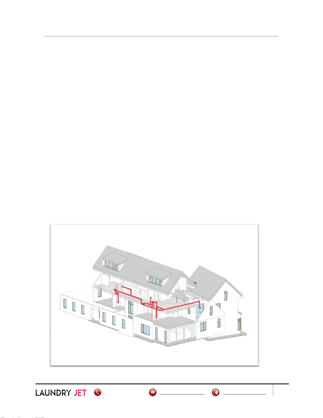
The Laundry Jet installation is comprised of three elements:
Laundry Jet Ports mounted in bedrooms, dressing rooms or bathrooms
The laundry room Wall mounted or Cabinet Mount Vacuum Unit
The PVC pipe and fittings that connect the ports to the laundry room through the
attic space
Vacuum Laundry Pipe
Laundry Jet specifies 6" SDR35 White Solvent Weld PVC pipe and fittings. This piping is
light weight to make install quick and easy.
PVC piping is designed to have a smooth transition in between fittings and connections
which ensures that clothing, bedding and towels will travel smoothly to the laundry
room.
Pipe & Fittings
6" SDR35 White Solvent Weld PVC pipe 10′ x 6”
All Fittings are 6" SDR35 White Solvent Weld
Introduction
+1.800.867.4580 sales@laundryjet.com www.laundryjet.com
6
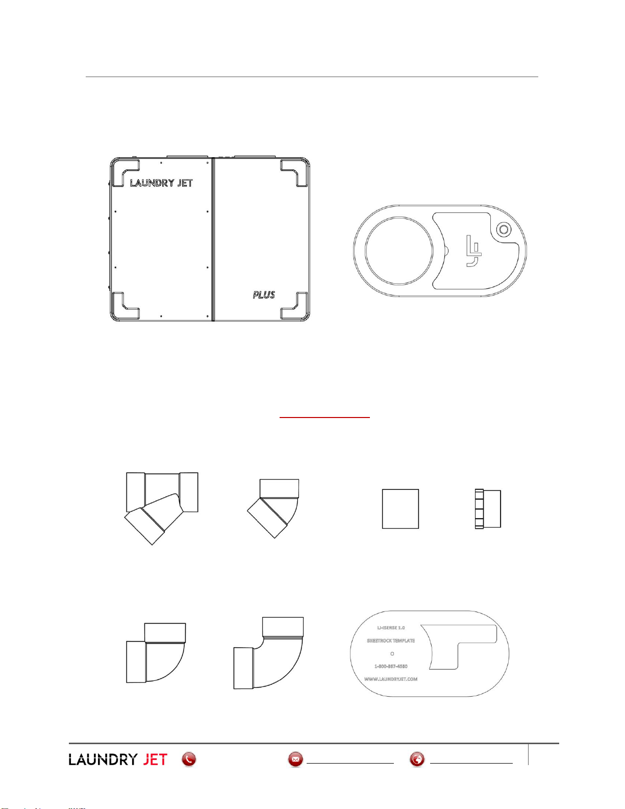
2Contents
Laundry Jet Plus Jet Pack ISense Port
6 Inch Wye 6 Inch 45° Elbow 6 Inch Coupler 6 Inch Cleanout
6 Inch 90° 6 Inch Swept 90° ISense Sheetrock Template
Contents
Pipe Components
All Fittings are 6" SDR35 White Solvent Weld

+1.800.867.4580 sales@laundryjet.com www.laundryjet.com
7
3Pipe Installation Overview
Components
Port 90 Assembly 6 Inch Wye 6 Inch Cleanout
Adapter
6 Inch 45° Elbow ISense Sheetrock Template Cable Bundle
Tools
Cordless Drill Sawzall Tape Measure
Clear 2 Part PVC Glue 1" Wood Screw Plumber's Metal Strapping Tape
Pipe Installation
+1.800.867.4580 sales@laundryjet.com www.laundryjet.com
8
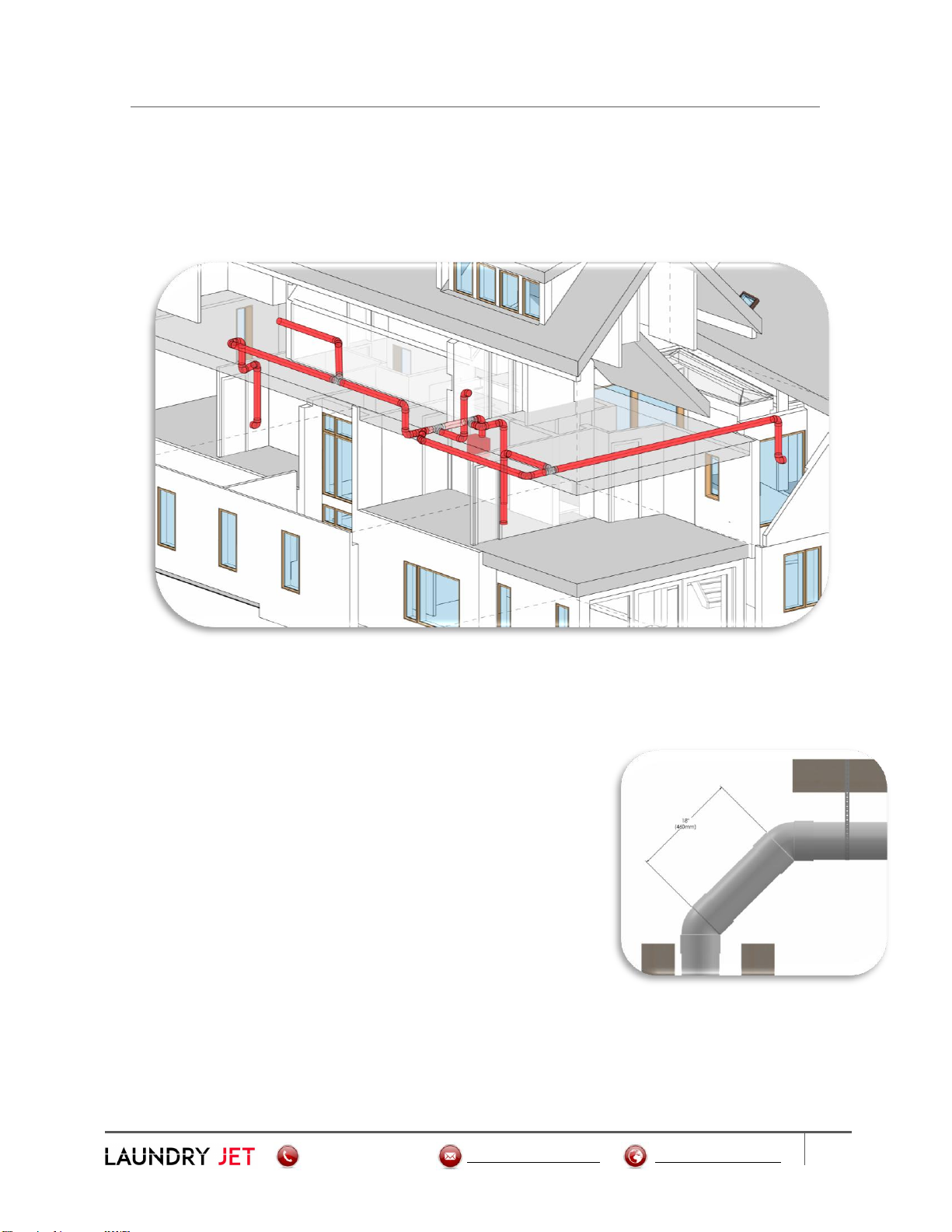
3.1 Pipe Installation Overview
Pipe Installation Standards
Required Piping Installation Standards
All joints must use a minimum entry angle of 45 degrees with a break distance of 18
Inches (460 MM). See Image below.
Pipe cuts must be straight and de burred before seating.
Pipe must be completely seated in fitting connections.
Seal all joints using standard PVC glue.
Connections must be glued around 360 degrees
to ensure maximum system performance.
System must be strapped with “plumbers tape”
(or equivalent) every 6 feet. Port 90 must be
strapped and secured prior to Port installation.
Install Cleanout ports every 50 feet on angled runs. Straight trunk lines can run up
to 100 feet with cleanouts at either end.
Pipe Installation

+1.800.867.4580 sales@laundryjet.com www.laundryjet.com
9
3.2 Pipe Installation Overview
Port Drop Installation
Mount port 90 using the Port 90 Mount Bracket. See Page 11 for Port 90 Installation.
Use a standard SDR 6" Swept 90 for your Port Drop Installation. Block and strap
drop line at midway point
Port Drop Installation
+1.800.867.4580 sales@laundryjet.com www.laundryjet.com
10
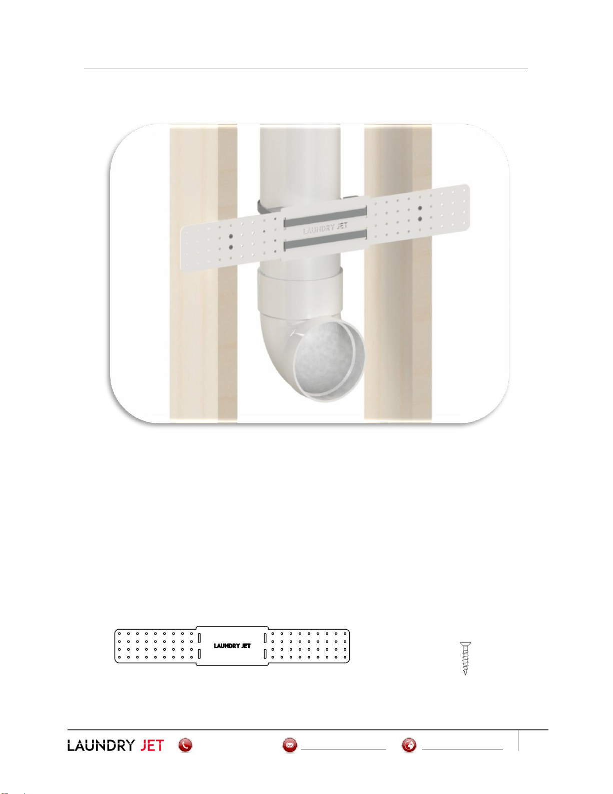
3.3 Pipe Installation Overview
Port 90 Installation
▪Port 90 must be installed with front face of Port 90 flush with the finished face of
interior wall.
▪Port 90 must be installed on a plum horizontal port drop line.
▪Use the Port 90 Mount Bracket to align and secure the Port 90 to the frame ( unless
a remodel)
Pipe Mount Bracket 1" Wood Screw
Port 90 Installation
Table of contents
Other LAUNDRY JET Laundry Appliance manuals


