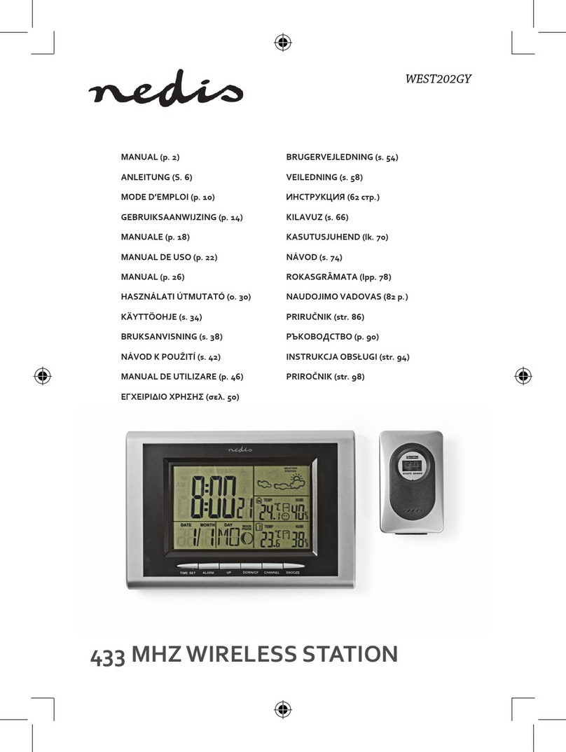
Hideki TE 529EL User manual

Weather Station TE 529EL
USER MANUAL
INTRODUCTION :
Congratulations on your purchase of the weather station TE529EL with wireless sensor and radio
controlled clock.
The basic package comes with a main unit (the temperture/clock station) and a remote unit (the
thermo sensor).
The main unit has a memory for the maximum and minimum temperature and humidity of different
sites. It can receive data from up to 3 remote units.
The remote units have a range up to 30 meters, this range can be influenced by several factors
(concrete walls, electric wires, other sending devices, etc.).
The sensors are weatherproof and can be used outdoors, but should not be submerged into water or
hung in a place where rain can reach the unit.
The clock/calendar function is radio controlled. The day can be displayed in 5 languages and the unit
has a 2 minute crescendo weekly and daily alarm.
The clock is synchronised with the atom clock in Frankfurt /Main, Germany. This clock has a range of
1.500 km and your clock will receive the time signal 12 to 24 times a day and will correct, if necessary.
When you first operate your clock, it can take up to 60 minutes before the radio signal is received and
the correct time is set.
When you put the main unit and the remote unit next to each other, you will notice a minimal difference
in temperature. This is caused by the software used and the insulation of the outdoor sensor. This
sensor is calibrated on the average outdoors temperature, whereas the main unit is calibrated on the
average indoors temperature. This is no defect in the units.
At temperatures below freezing point the operation can be distorted. This is caused because the
batteries cannot deliver the power needed to operate the unit correctly. You can avoid this by using
branded batteriees and change them just before the winter starts.
MAIN FEATURES
Main Unit

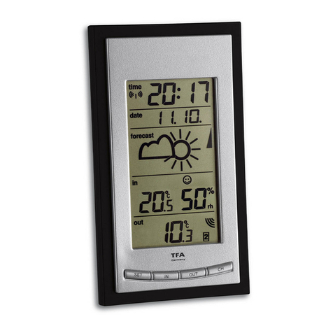
A 4 Line LC Display
Facilitates easy reading of weather forecast, indoor and outdoor temperatures, indoor and
outdoor humidity, trends for temperature, calendar clock.
B Channel Button
Selection of remote sensor to be displayed (for remote sensor 2 and 3).
C Memory Button (MEM)
Recalls the maximum and minimum temperatures as well as maximum and minimum
humidity for indoors and remote sensors.
D Mode Button (MODE)
Toggles the display modes and confirms entry while setting the values for display.
E Alarm Button
Displays the alarm time and sets the alarm status.
F Snooze/Light Button
Activates the snooze function and backlight.
G Wall Mount Hole
For mounting the main unit on a wall.
H Up Button ( )
Advances the value of a setting or turns on or off the radio controlled clock reception.
I Down Button ( )
Decreases the value of a setting or activates the remote outdoor thermometer reception.
J Battery Compartment
Accommodates 2 Mignon batteries (1,5 V, Type AA).
K Removable Table Stand
For standing the main unit on a flat surface.

Remote Sensor Unit
C/F
E

A Battery Compartment
Accommodates 2 Mignon batteries (1,5 V, Type AA).
B Reset Button
Resets all functions after changing the channels.
C Channel Selector
Select the channel before the batteries are installed.
D Wall Mount Hole
For mounting the sensor on the wall.
E LED Control Light
Flashes once, when the remote unit transmits a reading.
Flashes twice, when low battery is detected on sensor unit.
F °C/°F Switch
Selects between Centigrade (°C) and Fahrenheit (°F)
Installation of Batteries
Remote Sensor:
1.
Remove the 2 screws on the battery cover to open the battery compartment at the rear of
the sensor.
2.
Select the desired channel: 1, 2 or 3.
Note: If you want to use more than one remote sensor, each sensor must be designated a
separate channel.
3.
Insert 2 Mignon batteries (1,5V, Type AA) strictly according to the polarities shown inside the
compartment.
4.
Close the battery cover and fix with screws.
Weather Station (Main Unit):
1.
Open the battery compartment at the rear of the main unit.
2.
Insert 2 Mignon batteries (1,5V, Type AA) strictly according to the polarities shown inside the
compartment.
3.
Close the battery cover.
Low Battery Warning
When the capacity of batteries of the remote sensor is low, a crossed battery symbol will
appear in the humidity and outdoor temperature display of the main unit. Please replace both of
the low batteries with new ones.
How to Use the Table Stand or Wall Mounting
The main unit has a removable table stand. It may also be mounted on the wall after removing
the stand.The remote sensor can also be stood or hung on the wall.
The maximum range of the signal is 30 m. It is reduced, however –when the radio signal is
interrupted by a wall, a window or the like. Depending upon the material and angle involved, the
range can be reduced down to just a few meters. Different positioning of the sensor and the
main unit should be tested in order to obtain an optimal location for both units before deciding
upon a final position.
Though the housing of the sensor and weather station is weather proofed, we recommend to
place both out of direct sunlight and protected against rain and snow.
Sending and Receiving of Radio Signal
As soon as the batteries are inserted properly, the main unit begins a two minute search for the
remote sensor signal. The units are then synchronized. The remote sensor transmits readings
with temperature and humidity data approxymately every 45 sec. Reception at the main unit is
confirmed on the LC display, when the received outdoor temperature and humidity is updated.
The main unit will automatically update its readings in intervals of approxymately 45 sec. For
control purposes the LED on the remote sensor is lit during the transmission.
If no signal are received, blanks “--,-“will appear in the LC display of the main unit. Press

button for 2 sec. To enforce another search whereby the main unit and remote sensor will again
be synchronized.
Indoor and Outdoor Temperatures
The outdoor temperature appears in the middle of the LC display an in the lower part the indoor
temperature is shown. If the transmission from the remote sensor to the main unit is interrupted
for more than 2 minutes”--,-“begins to blink in the display. When this occurs check the remote
sensor. You may wait until the radio signal is transmitted again or press button for 2 sec.. The
main unit and remote sensor will again be synchronized.
Indoor and Outdoor Humidity
Along with the teperature the humidity is shown on the LC display in %. On the lower line you will
fid the indoor values and on the upper the outdoor values. Data is transferred simultaneously
from the remote sensor for both outdoor humidity and temperature. When the transmission is
interrupted, “--,-“appears in the humidity field of the display.
Interrupted Radio Signal Transmission
If the main unit does not register signals from the sensor , “--,-“will appear in the display of the
main unit. In this case press button for 2 sec. to synchronize the main unit with theremote
sensor. If this fails please check the following:
1.
The remote unit is still in place.
2.
The batteries of both the remote unit and main unit. Replace if necessary.
Note: When the temperature falls below freezing point, the batteries of outdoor units cannot
support a sufficient voltage. The effective range can lower to a few meters.
3.
The transmission is within range and path is clear of obstacles and interference. Shorten the
distance when necessary.
4.
Signals from other household devices such as computers, TV, security systems, mobile
phones etc. may interfere with the radio signals of this unit. If necessary, please relocate
weather station and sensor(s).
Status of the Signal Transmission
3 possible forms of transmission can be shown in LC display of themain unit:
The unit is in searching mode
Temperature readings are securely registered
No signals
Maximum and Minimum Temperature and Humidity
The weather station automatically stores the respective maximum and minimum values for
temperature and humidity for indoors and outdoors. To display these values press the MEM button:
•
Press once for display of minimum values for temperature and humidity stored since the last
clearing of the memory. The display will indicate MIN.
•
By pressing the MEM button a second time the maximum values for temperature and humidity will
be displayed. The display will indicate MAX.
•
By pressing the MEM button for 2 seconds stored values will be erased. The automatically storing
of minimum and maximum values begins anew.
The minimum and maximum values of the selected remote sensor (1,2, or 3) are also displyed by
pressing the MEM button. Each channel must be cleared separately.
Trend Display for Temperature and Humidity
The LC display of the main unit has four trend indicators, which depict the tendence the temperature
and humidity will be changing.
•
Trend arrow for indoor temperature
•
Trend arrow for outdoor temperature

•
Trend arrow for indoor humidity
•
Trend arrow for outdoor humidity
Arrow indicator
Temperature
Humidity
Trend Rising Steady Falling
Comfort Level Indicator
The comfort level indicators COMFORT, WET or DRY will tell you if the current environment is
comfotable, too wet or too dry. The following indicators will be displayed on the weather station:
Display Temperature Range Humidity Range Reflects
COMFORT 20°C to 25° C 40% to 70% Ideal range for both
relative humidity and
temperature
WET -5°C to +50° C over 70% Excess moisture
DRY -5°C to +50° C under 40% Too dry
(inadequate moisture)
No indicator under 20°C
or over 25° C 40% to 70% No comment
Weather Forecast
The unit is capable of detecting atmospheric pressure changes. Based on collected data it can predict
the weather for the forthcoming 12 to 24 hours.
Display
Forecast Sunny Partially Cloudy Cloudy Rain Snow
Note:
•
The accuracy of a general-based weather forecast is 70%.
•
The weather forecast indicates the forthcoming change and not necessarily the current situation.
•
The symbol “sunny”applies also to night time. It indicates clear sky/without clouds.
Atmospheric Pressure Trend Indicator
The atmospheric pressure indicator in the weather forecast window of the main unit uses arrows to
indicate trend changes in atmospheric pressure and therefore weather changes:
Arrow indicator
Pressure
Trend Rising Steady Falling
Rising pressure = the weather is changing for the better
Falling pressure = the weather is changing for the worst
Radio Controlled Clock
The weather station is equipped with a radio controlled quartz clock. It functions with utmost precision
and is silent. The change from normal time to day light savings time is automatic.
•
After the batteries are inserted the clock will automatically search for the radio signal. This
process is completed within 3 to 5 minutes.

•
As soon as the radio signal has been received the time will be displayed (hour, minutes and
seconds). The symbol will appear in the display as confirmation of radio signal reception.
•
If the search for the radio signal is not successful this symbol will not appear. Instead the symbol
for signal search will be displayed. In this case the time has to be set manually.
•
Press button for 2 sec., in order to switch off the radio controlled quartz function. The symbol
for radio signal transmission will be deleted. By pressing the button again for 2 sec. , the radio
controlled reception will be turned on again.
Note: The radio controlled signal for time (DCF 77) is transmitted from the central atomic clock in
Frankfurt/Main, Germany.
Time and Date Display Modus
The main unit receives and displays together with the time signal the effective date. The MODE is
used to obtain this information.
•
Press 1 x and the time and weekday appears (hour, minutes and weekday).
•
Press 2 x and the time and weekday for a second time zone appears (hour, minutes and
weekday).
•
Press 3 x and the time with seconds of the second time zone appears (hour, minutes and
seconds).
•
Press 4 x and the actual date appears (day and month).
Manual Setting of Date, Time and Temperature
By pressing the MODE button for 2 sec. the value to be changed begins to blink. Use the button to
reduce and the button to increase the value. If the values are not numerical, the and button
will offer other possibilities. By pressing the MODE button the blinking, which indicates the value to be
changed, will move forward.
So the following values may be set:
1. Country (Germany=DE)
2. Select °C/°F
3. Calender Year
4. Month
5. Day
6. Sequence of Date (ay and onth or month and day)
7. Hour Format (12 or 24 hour)
8. Hour
9. Minutes
Note: When setting hours anew, the seconds return to 00.
Setting of the Second Time Zone
The actual time of a second time zone is programmed with the MODE button by calling up the
appropriate display. ZONE will appear in front of the time display.
Press MODE button for 2 sec. until 0:00 starts to blink in the LC display. Set the difference between
the local time and second time zone by using the and buttons, which will advance ore decrease
in 30 minute increments. The second time zone can differ between –13 and +15 hours from local time.
Confirm data entered with a short pressing of the MODE button.

Alarm
The weather station has an integrated alarm with 3 functions:
1.
Weekday alarm: The alarm is activated at the same time each day at the preset time.
appears in the display.
2.
Single alarm: The alarm is activated for one time waking. is shown in the display.
3.
Pre-alarm: When the outdoor temperature sinks to 2°C or below, the preset alarm (single alarm or
weekday) can be activated 15, 30, 45, 60 or 90 minutes earlier than the selected waking time.
PRE-ALARM will then be displayed.
Setting the Alarm
Press ALARM button on the upper side of the unit to select modus W, S or PRE-ALARM. Then press
ALARM button for 2 seconds until the hour display of the< alarm begins to blink. By pressing or
you can increase or decrease the hour value. The press ALARM again to confirm hour values. The
minute display then begin to blinkj. Follow the same procedures as for the hour value.
Snooze Alarm and Display Lighting
The SNOOZE button is on the upper side of the weather station. The alarm is deactivated upon
pressing this button for approximately 8 minutes after which it sounds again. By pressing ALARM the
alarm can be turned off.
The SNNOZE function is combined with a lighting of the display for approximately 4 seconds.
Activating / Deactivating Alarm Setting
By pressing ALARM at the upper side of the weather station you activate the alarm modus W, S or
PRE-AL. Deactivation is done by pressing , to turn the alarm off, or , to reactivate the alarm.
Precautions
•
In the case of a defect do not attempt to take the weather station apart or repair yourself as the
guarantee is then invalid.
•
The weather station is a technical precision device, which can be damaged by dropping, banging
or other forceful treatment.
•
The main unit is not weather proof. It should therefore be protected from rain and humidity, which
could otherwise cause damage.
•
Never attempt to clean the weather station with benzine or other abrasive cleaning solutions.
Specifications
Barometer:
•
Weather forecast for approximately 12 to 24 h depicted symbols
•
Humidity trend indicator
Thermometer
•
Radio signal transmission of temperature data from up to 3 remote sensors (one sensor included)
•
Radio signal transmission range max. 30 m
•
Measured outdoor temperature range: -20°C to + 60°C
•
Built-in sensor for room temperature:
•
Measured indoor temperature range: -5°C to + 50°C
•
Temperature trend indicator
•
Minimum and maximum temperature stored in memory

Hygrometer:
•
Display of 25% to 95% for indoor and outdoor humidity
•
Hymidity trend indicator
•
Minimum and maximum humidity stored in memory
•
Comfort level indicator:WET, COMFORT, DRY
Radio Signal Controlled Clock
•
Precise, silent and battery operated
•
Radio signal controlled time (DCF 77) with automatic change between daylight savings time and
normal time
•
Radio signal reception can be switched off
•
LC display of time, date, weekday and two time zones
•
2 alarm functions and pre-alarm
General:
•
Transmission frequency: 433 MHz
•
Power supply for main unit and remote sensor: each 2 Mignon batteries (1,5V, Type AA)
•
Stand or wall hung
•
Main unit: 95 x 174 x 30 mm and 231g (without batteries)
Remote Sensor: 55 x 101 x 24 mm and 60g (without batteries)
Important Note
1. The above content and the devices are subject to changes without prior notice.
2. The manufacturer and its suppliers hold no responsibility to you or no any other person for any
damage expenses, lost profits, or any other claims arisen by improper handling, misuse or failure
to comply with the correct use of this product as described in this instruction manual.
EC-DECLARATION OF CONFORMITY
Product. TE529 EL
This product contains the approved transmitter and complies with the essential requirements of Article
3 of the R&TTE 1999/5/EC Directives, if used for its intended use and that the following standard(s)
has/have been applied:
Efficient use of radio frequency spectrum
(Article 3.2 of R&TTE 1999/5/EC Directive)
applied standard(s) EN 300 220-1,3:2000
Electromagnetic compatibility
(Article 3.1b of R&TTE Directive)
applied standard(s) EN 301 489-1,3:2000
applied standard(s) EN 300 339:2000
Additional information:
The product is therefore conform with the Low Voltage Directive 73/23/EC, the EMC Directive
89/336/EC and R&TTE Directive 1999/5/EC (appendix II) and carries the respective CE Marking.
RTTE Compliant Countries:
All EU countries, Switzerland
and Norway
Important Notes
Precautions with regard to batteries
Batteries can be highly dangerous, if swallowed.

Therefore it is necessary to keep the batteries and the appliance out of reach of small children. If a
battery has been swallowed, seek medical advice immediately.
Always remove batteries as soon as they are empty, as they might leak and cause damage. Please
replace always all batteries at the same time.
The batteries provided must not be charged or re-activated by any other means! They must not be
dismantled, thrown into fire or short-circuited!
Batteries need to be disposed off properly. For this purpose, shops selling batteries provide
special containers for environmentally friendly disposal. Furthermore, empty batteries will
be taken back at public waste collection points.
Waste Management
At the end of the life cycle of the blood pressure monitor please make sure, that it is
disposed off properly. The waste management of this unit has to be in line with the national
law transferring the WEEE-directive of the European Union into national law of the country
where you are living.

GUARANTEE
Within the guarantee period of 24 months, effective from the date of purchase, repairs of this device
will be done free of charge, if the defect is caused by material defects or errors in the manufacturing
process. During the guarantee period the defective unit can be returned to the beneath mentioned
service address. You will either receive a new or repaired unit free of charge, if the guarantee applies.
If the guarantee period is run out you have also the possibility to return a defective unit to the beneath
mentioned address for repair. These repairs will be charged accordingly.
The guarantee does not apply for defects caused by improper treatment of the unit, as e.g. breaking
as a consequence of a hard fall or improper use due to the fact that the instruction booklet was not
studied carefully. The guarantee does also not apply, if unauthorized persons or companies have tried
to repair a defective unit.
If you have to apply unfortunately for a guarantee please contact beneath mentioned telephone
number or send the defective unit to the beneath mentioned service address. Please take care that
following information is included in your mail:
1. Description of the defect
2. Invoice with date of purchase
Defective units without this information will be repaired at your expense and returned to the sender by
cash on delivery.
Service:
SBC Buchsbaum GmbH
Franzensgasse 26 / Top I
A-1050 Wien
phone: +43-1- 585 5838
facsimile: +43-1- 585 5935
E-Mail: [email protected]
Manufacturer:
Hideki Electronics Limited
88 Lei Muk Road,
Kwai Chung, N.T.
Hongkong
Importer into the EU:
SBC Buchsbaum GmbH
Franzensgasse 26 / Top I
A-1050 Wien
Table of contents
