Froggit WH1080SE User manual

- 1 -
WH1080SE
Manuel (EN)
About this manual
Thank you and congratulations on selecting this professional weather station!
We are positive you will enjoy the benefits of accurate weather readings our
instruments offer. A solar powered weather station has the advantage of being
able to provide energy for long periods of time.
This manual will guide you step-by-step through setting up your device. Use this
manual to become familiar with your professional weather station, and save it for
future reference.
Glossary of Common Terms
DCF/WWVB/MSF
The DCF WWVB or MSF time signal is an AM modulated time-of-day signal broadcasted
by the Federal Government of Germany, NIST from USA or National Physical Lboratory.
The time base is generated from an atomic time generator which is accurate to 10 billion
of one second.
LCD
“LCD” is an acronym for ”Liquid Crystal Display”. This is a common type of
display screen used in televisions, computers, watches, and digital clocks.
BAROMETER & BAROMETRIC PRESSURE
A barometer is a device that measures the pressure of the air pushing on it—this
measurement is called the barometric pressure. We don’t actually feel the
barometric pressure because the air pressure is pushing equally in every
direction.
RELATIVE AIR PRESSURE
Relative air pressure is the same as the barometric pressure. The calculation
of relative air pressure is a combination of the absolute air pressure and the
altitude.
ABSOLUTE AIR PRESSURE
Absolute air pressure is the actual air pressure on the barometer without regard
to altitude.
INCHES OF MERCURY (inHg)
Inches of Mercury are the common unit of measurement for air pressure in the
United States.
HECTOPASCALS (hPa)
Hectopascals are the common units of measurement for air pressure in the

- 2 -
International System (SI) of measurement. The hectopascal holds the same
value
Important Note:
Before inserting batteries, please carefully read the operation manual.
The touch screen weather station includes a base station (receiver), an
integrated outdoor unit consists of solar-panel/wind direction sensor/wind speed
sensor/rain gauge/thermo-hygro sensor, USB cable
The Base Station is equipped with a Touch Screen LCD Monitor and allows the
display of a large variety of time and weather data.
Left Top LCD: IN-OUT temperature and humidity
Right Top LCD: Wind and Rain measurement
Left Middle LCD: Weather Forecast(Tendency)
Right Middle LCD: Air Pressure and Air Pressure History
Bottom Line LCD: Time and Date, Memory Data Usage
Note: The presence of the "Alarm-On icon" in the section means that the
particular alarm has been enabled.
An added feature of the Weather Station is the readout of all measured and

- 3 -
displayed time and weather data on a PC.
Important Operation Notes
All actions and functions of the weather station are started on the touch screen
by slightly touching (not pressing!) the related areas, touch the flashing +,
ON/OFF or –to make the corresponding selection or increase the value.
Every time a programming step is activated by touching a switching area on the
Touch Screen a tone will sound, and the back light is switched on for a few
seconds as well.
If no areas are pressed for 30 seconds, the LCD will automatically revert to the
normal display mode (automatic time out).
Set up Guide
Before placing and installing all components of the weather station at there
final destination, please set up the weather station with all parts being nearby
for testing the correct function.
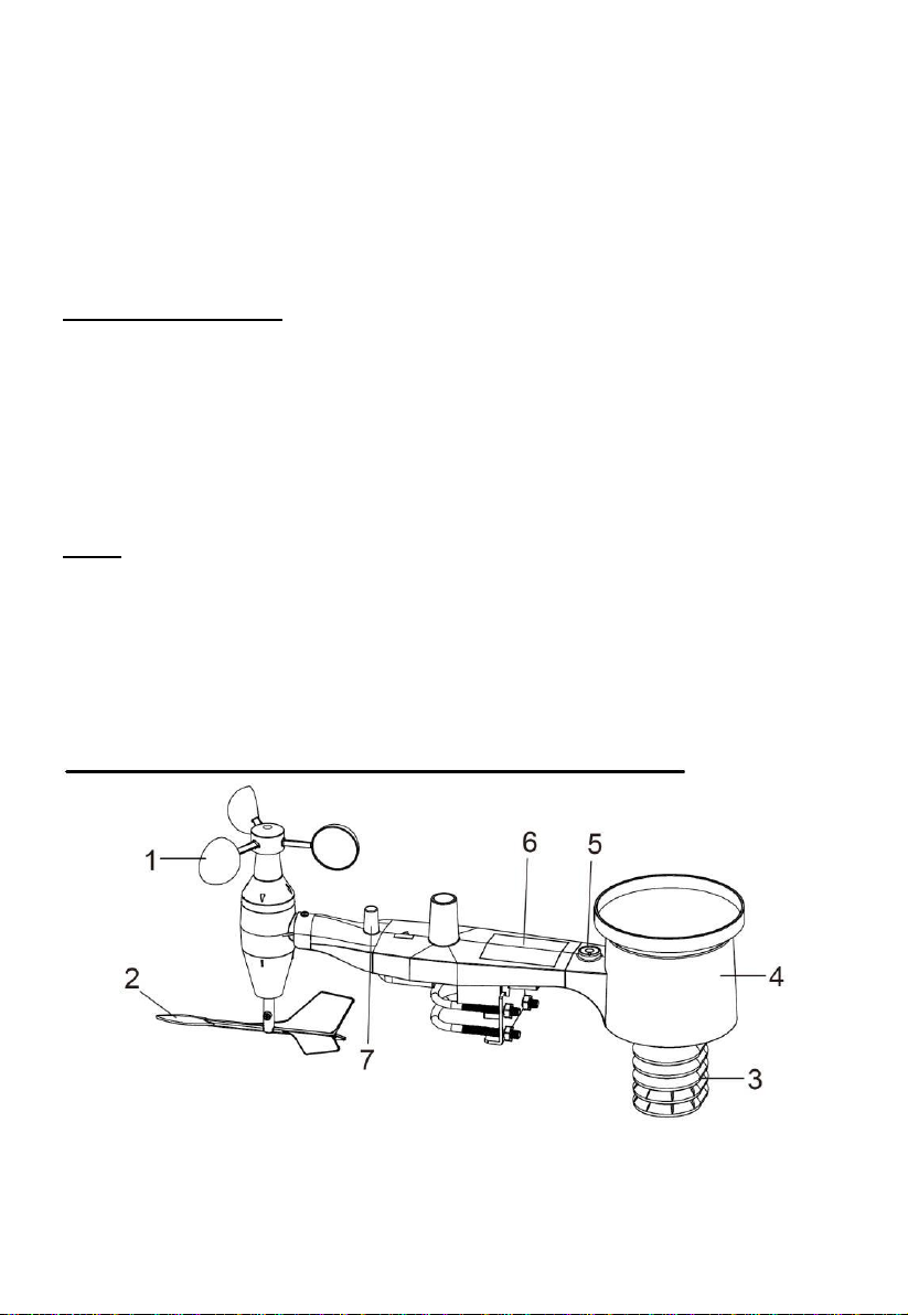
Setting up the base station and transmitter
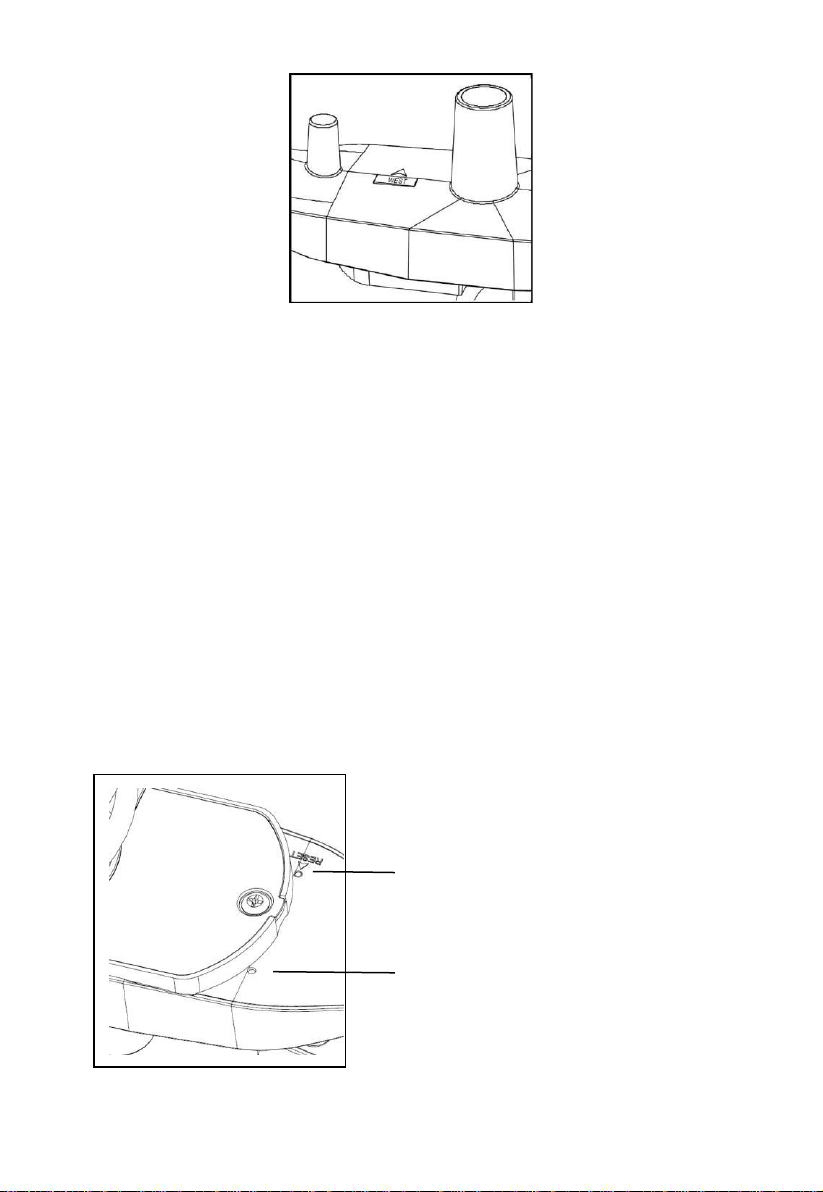
Insert two pieces of LR6 (AA size) batteries into the transmitter, the LED
located in the middle front case of transmitter will be turned on for 4 seconds,
then it will be off and start to work normally. The transmitter will make a data
transmission and then start radio controlled time reception routine. If time
signal can be detected correctly, the LED will start to flash 5 times, and then
the LED will be on for 20s, indicating time signal has been found correctly.
When time signal is bad and reception is not possible, the transmitter will
terminate radio controlled time reception within one minute and resume
normal mode. When there is a data transmission happened, the LED will be
on for 20ms. During radio controlled time reception period, there is no
transmission and normal transmission will only resume after time reception
routine is complete. The longest time for radio controlled time reception is 5
minutes.
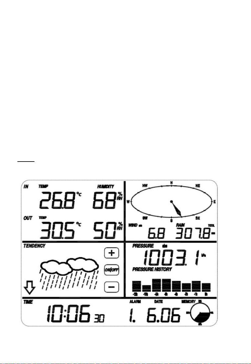
After inserting the batteries into the Weather Station, all LCD segments will
be turned on for a few seconds, all possible display segments are turned on
for checking.
After this, the weather station will make initial measurement and start to
register the transmitter (the radio reception icon will be turned on). Do not
press any key before outdoor sensor data received, otherwise the outdoor
sensor learning mode will be terminated. When outdoor transmitter has been
registered, the base station will automatically switch to the normal display

- 4 -
mode from which all further settings can be performed by the user.
If no RCC signal is detected in the initial setup, the transmitter will try once
every 6 hours to get an RCC signal until a signal is received. Once the
transmitter receives the RCC signal it will transmit the signal to the monitor.
On the monitor the RCC icon will be displayed, if the monitor doesn’t receive
the RCC signal or loses the signal the RCC icon will not be display.
Register transmitter
If no outdoor weather data is displayed or the signal to the sensors is lost
during setting up, mounting, hold the RESET button of outdoor sensor and
re-insert the batteries of base station to synchronize the base station to
sensors. Without being synchronized, weather data will not be received.
NOTE: Wait two minutes before re-insert the batteries of transmitter for
proper reset.
Note:
The best condition for reception is at night, between midnight and 6:00am –
when there is less atmospheric interference.
Getting Started
Setup Sensors
Figure 1

- 5 -
Figure 2
1. Wind Speed Sensor
2. Wind Vane
3. Thermo-hygro sensor
4. Rain collector
5. Bubble level
6. Solar panel
7. Antenna
8. U-Bolt
9. Battery compartment
10. Reset button
11. LED Indicator: light on for 4s if the unit power up. Then the LED will flash
once every 48 seconds (the sensor transmission update period).
1. Install U-bolts and metal plate
Installation of the U-bolts, which are in turn used to mount the sensor
package on a pole, requires installation of an included metal plate to receive
the U-bolt ends. The metal plate, visible in Figure 3 has four holes through
which the ends of the two U-Bolts will fit. The plate itself is inserted in a
groove on the bottom of the unit (opposite side of solar panel). Note that one
side of the plate has a straight edge (which goes into the groove), the other
side is bent at a 90-degree angle and has a curved profile (which will end up
“hugging” the mounting pole). Once the metal plate is inserted, insert both
U-bolts through the respective holes of the metal plate as shown in Figure 3.

- 6 -
Figure 3: U-Bolt installation
Loosely screw on the nuts on the ends of the U-bolts. You will tighten these
later during final mounting. Final assembly is shown in Figure 4.
Figure 4: U-Bolts and nuts installed
The plate and U-Bolts are not yet needed at this stage but doing this now
may help avoid damaging wind vane and wind speed cups later on.
Handling of the sensor package with wind vane and speed cups installed to
install these bolts is more difficult and more likely to lead to damage.
2. Install wind speed cups
Push the wind speed cup assembly onto the shaft on the top side of the
sensor package, as shown in Figure 5 on the left side. Tighten the set screw,
with a Philips screwdriver (size PH0), as shown on the right side. Make sure
the cup assembly can rotate freely. There should be no noticeable friction
when it is turning.

- 7 -
Figure 5: Wind speed cup installation diagram
3. Install wind vane
Push the wind vane onto the shaft on the opposite side ofthe wind cups, until
it goes no further, as shown on the left side in Figure 6. Next, tighten the set
screw, with a Philips screwdriver (size PH0), as shown on the right side, until
the wind vane cannot be removed from the axle. Make sure the wind vane
can rotate freely. The wind vane’s movement has a small amount of friction,
which is helpful in providing steady wind direction measurements.
Figure 6: Wind vane installation diagram
4. Install Batteries
Open the battery compartment with a screwdriver and insert 2 AA batteries
in the battery compartment. The LED indicator on the back of the sensor
package will turn on for four seconds and then flash once every 48 seconds
indicating sensor data transmission(the sensor transmission update period).

- 8 -
Figure 7: Battery installation diagram
Note: If LED does not light up or is on permanently, make sure the
battery is inserted the correct way and inserted fully, starting over if
necessary. Do not install the batteries backwards as it may permanently
damage the outdoor sensor.
Note: We recommend Lithium batteries for cold weather climates, but
alkaline batteries are sufficient for most climates. Rechargeable batteries
have lower voltages and should never be used.

- 9 -
5. Mount outdoor sensor
Before you mount
Before proceeding with the outdoor mounting detailed in this section, you need
to make sure the base station can receive the data from outdoor sensor, while
you keep the assembled outdoor sensor package nearby (although preferably
not closer than 1.5m from the console). This will make any troubleshooting and
adjustments easier and avoids any distance or interference related issues from
the setup.
After setup is complete and everything is working, return here for outdoor
mounting. If issues show up after outdoor mounting they are almost certainly
related to distance, obstacles etc.
Reference Figure 8, the mounting assembly includes two U-Bolts and a bracket
that tightens around a 1 to 2” diameter pole (not included) using the four U-Bolt
nuts.
Figure 8: Sensor package mounting diagram
Note
Beside the antenna, there is an arrow icon with ”NORTH”words (Figure
9)representing the direction of north. The sensor body has to be adjusted so that
the “NORTH”indication is facing to real north direction in your location. A
compass device is recommended to help adjust direction. Permanent wind
direction error will be introduced when the outdoor sensor is not installed in right
direction.

- 10 -
Figure 9
Now look at the bubble level. The bubble should be fully inside the red circle.
If it is not, wind direction, speed, and rain readings may not operate
correctly or accurately. Adjust the mounting pipe as necessary. If the bubble
is close, but not quite inside the circle, and you cannot adjust the mounting
pipe, you may have to experiment with small wooden or heavy cardboard
shims between the sensor package and the top of the mounting pole to
achieve the desired result (this will require loosening the bolts and some
experimentation).
Make sure you check, and correct if necessary, the northly orientation as
the final installation step, and now tighten the bolts with a wrench.
6. Reset Button and Transmitter LED
Using a bent-open paperclip, press and hold the RESET BUTTON (see
Figure 10) to affect a reset: the LED turns on while the RESET button is
depressed, and you can now let go. The LED should then resume as
normal, flashing approximately once every 48 seconds.
Figure 10
RESET button
LED light

- 11 -
7. Best Practices for Wireless Communication
Note: To insure proper communication, mount the remote sensor(s) upright on
a vertical surface, such as a wall. Do not lay the sensor flat.
Wireless communication is susceptible to interference, distance, walls and metal
barriers. We recommend the following best practices for trouble free wireless
communication.
1. Electro-Magnetic Interference (EMI). Keep the console several feet
away from computer monitors and TVs.
2. Radio Frequency Interference (RFI). If you have other 433/868/915
MHz devices and communication is intermittent, try turning off these
other devices for troubleshooting purposes. You may need to relocate
the transmitters or receivers to avoid intermittent communication.
3. Line of Sight Rating. This device is rated at 300 feet line of sight (no
interference, barriers or walls) but typically you will get 100 feet
maximum under most real-world installations, which include passing
through barriers or walls.
4. Metal Barriers. Radio frequency will not pass through metal barriers
such as aluminum siding. If you have metal siding, align the remote and
console through a window to get a clear line of sight.
The following is a table of reception loss vs. the transmission medium. Each
“wall” or obstruction decreases the transmission range by the factor shown
below.
Medium
RF Signal Strength Reduction
Glass (untreated)
5-15%
Plastics
10-15%
Wood
10-40%
Brick
10-40%
Concrete
40-80%
Metal
90-100%
Set up display
Note: Because of the default settings already determined by the manufacturer it
may not be necessary for the majority of users to perform –except the
Relative Air Pressure (see further down) - any further basic settings.
Changes, however, can be easily made.
For basic settings, the following menu is started by touching the Touch Screen in
the desired display area.
The basic settings can now be performed in the following successive order:

- 12 -
Note: setting procedure can be exited at any time by touching any other function
area (except “+”, “-” or “ON/OFF”).
indoor temperature
Activate the indoor temperature related setting by
1)Touch the INDOOR TEMPERATURE section, + button and –button will be
flashing. Touch the + button or –button to Shift the display unit between ℃and
℉
2)Touch the INDOOR TEMPERATURE section again to set the indoor
temperature high alarm function, the +, ON/OFF and –button will be flashing,
HI AL icon will light up. Touch the+ button or –button to change the value, hold
the+ button or –button for 3s to change the number in great step. Touch the
ON/OFF button to choose the alarm on or off (if alarm is enabled, the speaker
icon will be turned on indicating the alarm function has been enabled).
3)Touch the INDOOR TEMPERATURE section the third time to set the indoor
temperature low alarm function, the +, ON/OFF and –button will be flashing,
LO AL icon will light up. Touch the+ button or –button to change the value,
hold the+ button or –button for 3s to change the number in great step. Touch
the ON/OFF button to choose the alarm on or off (if alarm is enabled, the
speaker icon will be turned on indicating the alarm function has been
enabled).
4)Touch the INDOOR TEMPERATURE section the fourth time to display
maximum indoor temperature record, the maximum records will be flashing,
MAX icon will light up as well. Hold the flashing max value for 3s, the
maximum value will be reset to current reading.
5)Touch the INDOOR TEMPERATURE section the fifth time to display minimum
indoor temperature record, the minimum records will be flashing, MIN icon will
light up as well. Hold the flashing min value for 3s, the minimum value will be
reset to current reading.

- 13 -
outdoor temperature
Activate the outdoor temperature related setting by
1)Touch the OUTDOOR TEMPERATURE section, + button and –button will be
flashing. Touch the + button or –button to Shift the display between Outdoor
Temperature, Wind Chill and Dew Point.
2)Touch the OUTDOOR TEMPERATURE section again, + button and –button
will be flashing. Touch the + button or –button to Shift the display unit
between ℃and ℉
3)Touch the OUTDOOR TEMPERATURE section the third time to set the
outdoor temperature high alarm function, the +, ON/OFF and –button will be
flashing, HI AL icon will light up. Touch the+ button or –button to change the
value, hold the+ button or –button for 3s to change the number in great step.
Touch the ON/OFF button to choose the alarm on or off (if alarm is enabled,
the speaker icon will be turned on indicating the alarm function has been
enabled).
4)Touch the OUTDOOR TEMPERATURE section the fourth time to set the
outdoor temperature low alarm function, the +, ON/OFF and –button will be
flashing, LO AL icon will light up. Touch the+ button or –button to change the
value, hold the+ button or –button for 3s to change the number in great step.
Touch the ON/OFF button to choose the alarm on or off (if alarm is enabled,
the speaker icon will be turned on indicating the alarm function has been
enabled).
5)Touch the OUTDOOR TEMPERATURE section the fifth time to display
maximum outdoor temperature record, the recorded maximum value will be
flashing, MAX icon will light up. Hold the flashing max value for 3s, the
maximum value will be reset to current reading.
6)Touch the OUTDOOR TEMPERATURE section the sixth time to display
minimum outdoor temperature record, the recorded minimum value will be
flashing, MIN icon will light up as well. Hold the minimum value for 3s, the
minimum value will be reset to current reading.

- 14 -
Indoor humidity
Activate the indoor humidity related setting by
1)Touch the INDOOR HUMIDITY section again to set the indoor humidity high
alarm function, the +, ON/OFF and –button will be flashing, HI AL icon will
light up. Touch the+ button or –button to change the value, hold the+ button or
–button for 3s to change the number in great step. Touch the ON/OFF button
to choose the alarm on or off (if alarm is enabled, the speaker icon will be
turned on indicating the alarm function has been enabled).
2)Touch the INDOOR HUMIDITY section again to set the indoor humidity low
alarm function, the +, ON/OFF and –button will be flashing, LO AL icon will
light up. Touch the+ button or –button to change the value, hold the+ button or
–button for 3s to change the number in great step. Touch the ON/OFF button
to choose the alarm on or off (if alarm is enabled, the speaker icon will be
turned on indicating the alarm function has been enabled).
3)Touch the INDOOR HUMIDITY section the third time to display maximum
indoor humidity record, the recorded maximum value will be flashing, MAX
icon will light up as well. Hold the maximum value for 3s, the maximum value
will be reset to current reading.
4)Touch the INDOOR HUMIDITY section the fourth time to display minimum
indoor humidity record, the recorded minimum value will be flashing, MIN icon
will light up as well. Hold the minimum value for 3s, the minimum value will be
reset to current reading.
Outdoor humidity
Procedures and settings are similar to Indoor humidity
Wind speed
Activate the wind related setting by

- 15 -
1)Touch the WIND SPEED section, + button and –button will be flashing. Touch
the + button or –button to Shift the display between Wind Average Speed and
Gust Speed.
2)Touch the WIND SPEED section again, + button and –button will be flashing.
Touch the + button or –button to select wind speed unit between km/h, mph,
m/s, knots, bft
3)Touch the WIND SPEED section the third time to set the high alarm function,
the +, ON/OFF and –button will be flashing, HI AL icon will light up. Touch
the+ button or –button to change the value, hold the+ button or –button for 3s
to change the number in great step. Touch the ON/OFF button to choose the
alarm on or off (if alarm is enabled, the speaker icon will be turned on
indicating the alarm function has been enabled).
4)Touch the Wind SPEED section the fourth time to set wind direction alarm
function, the wind direction arrow will start to flashing. Touch + or –to select
desired alarm for wind direction, press ON/OFF to enable or disable the wind
direction alarm.
5)Touch the Wind SPEED section the fifth time to display maximum wind speed
record, the recorded maximum value will be flashing, MAX icon will light up as
well. Hold the maximum value for 3s, the maximum value will be reset to
current reading.
Rain
Activate the rain related setting by
1)Touch the rain section, + button and –button will be flashing. Touch the +
button or –button to Shift the display between 1h,24h,week,month and total
rain.
2)Touch the rain section again, + button and –button will be flashing. Touch the
+ button or –button to select rain fall unit between mm,inch.
3)Touch the rain section the third time to set the high alarm function, the +,
ON/OFF and –button will be flashing, HI AL icon will light up. Touch the+
button or –button to change the value, hold the+ button or –button for 3s to
change the number in great step. Touch the ON/OFF button to choose the
alarm on or off (if alarm is enabled, the speaker icon will be turned on
indicating the alarm function has been enabled).
4)Touch the rain section the fourth time to display current maximum rain fall
record. Touch the rain section for 3s will reset the maximum rain fall value to
current value.

- 16 -
5)Touch the rain section the fifth time to reset rain fall value to 0 by pressing the
rain section for 3s, then 1h,24h,week,month and total rain will be reset to 0.
Weather forecast
1)Touch the WEATHER FORECAST section, + button and –button will be
flashing. Touch the + button or –button to Shift the display between SUNNY,
PARTLY CLOUDY and CLOUDY, RAINY icon
2)Touch the WEATHER FORECAST section again, + button and –button will be
flashing. Touch the + button or –button to set the pressure threshold from
2-4hPa(default 2hPa)
3)Touch the WEATHER FORECAST section the third time, + button and –button
will be flashing. Touch the + button or –button to set the storm threshold from
3-9hPa(default 4 hPa)
Pressure
1)Touch the PRESSURE section, + button and –button will be flashing. Touch
the + button or –button to Shift the display between Absolute pressure and
Relative pressure.
2)Touch the PRESSURE section again, + button and –button will be flashing.
Touch the + button or –button to Shift the display unit between hPa, inHg and
mmHg.
3)Touch the PRESSURE section the third time to set the Relative Pressure value.
The + and –button will be flashing, rel icon will light up. Touch the+ button or –
button to change the value, hold the+ button or –button for 3s to change the
number in great step.
4)Touch the PRESSURE section the forth time to set the pressure high alarm
function, the +, ON/OFF and –button will be flashing, HI AL icon will light up.
Touch the+ button or –button to change the value, hold the+ button or –
button for 3s to change the number in great step. Touch the ON/OFF button to
choose the alarm on or off (if alarm is enabled, the speaker icon will be turned

- 17 -
on indicating the alarm function has been enabled).
5)Touch the PRESSURE section the fifth time to set the pressure low alarm
function, the +, ON/OFF and –button will be flashing, LO AL icon will light up.
Touch the+ button or –button to change the value, hold the+ button or –
button for 3s to change the number in great step. Touch the ON/OFF button to
choose the alarm on or off (if alarm is enabled, the speaker icon will be turned
on indicating the alarm function has been enabled).
6)Touch the PRESSURE sections the sixth time to display maximum pressure
record, to display maximum pressure, the recorded maximum value will be
flashing, MAX icon will light up as well. Hold the maximum value for 3s, the
maximum value will be reset to current reading.
7)Touch the PRESSURE section the seventh time to display minimum pressure
record, to display minimum pressure record, the recorded minimum value will
be flashing, MIN icon will light up as well. Hold the minimum value for 3s, the
minimum value will be reset to current reading.
Note: when absolute pressure is selected, step 3 will be skipped since absolute
pressure is selected for display.
Pressure bar graph
Touch the PRESSURE BAR GRAPH section and then press + or –to toggle the
bar graph time scale between 12hrs or 24 hrs for pressure history.
Time
1)Touch the TIME section, + button and –button will be flashing. Touch the +
button or –button to adjust the contrast level from 0 to 8. (default 5)
2)Touch the TIME section again, + button and –button will be flashing. Touch
the + button or –button to set the time zone.
3)Touch the TIME section the third time, + button and –button will be flashing.
Touch the + button or –button to Shift the 12/24 hours format.
4)Touch the TIME section the fourth time to set the hour, the + and –button will
be flashing. Touch the+ button or –button to change the value.
5)Touch the TIME section the fifth time to set the Minute, the + and –button will
be flashing. Touch the+ button or –button to change the value.
Date

- 18 -
1)Touch the DATE section, + button and –button will be flashing. Touch the +
button or –button to shift between alarm time, date and week date.
2)Touch the DATE section again, + button and –button will be flashing. Touch
the + button or –button to Shift between DD-MM format and MM-DD format
for the date.
3)Touch the DATE section the third time, + button and –button will be flashing.
Touch the + button or –button to set the year. Hold the+ button or –button for
3s to change the number in great step.
4)Touch the DATE section the fourth time, + button and –button will be flashing.
Touch the + button or –button to set the month. Hold the+ button or –button
for 3s to change the number in great step.
5)Touch the DATE section the fifth time, + button and –button will be flashing.
Touch the + button or –button to set the day. Hold the+ button or –button for
3s to change the number in great step.
6)Touch the DATE section the sixth time, + button and –button will be flashing.
Touch the + button or –button to set the alarm hour. Hold the+ button or –
button for 3s to change the number in great step.
7)Touch the DATE section the seventh time, + button and –button will be
flashing. Touch the + button or –button to set alarm minute. Hold the+ button
or –button for 3s to change the number in great step. Touch ON/OFF to
enable or disable time alarm function.
Memory
Touch Memory section to activate history data toggle display, + button and –
button will be flashing. Press –to toggle forward to see earlier weather history
data together time stamp, press + to see later history weather data. When
history data displayed, the corresponding time will be displayed at the time
section area( History data saving interval can only be changed using the PC
software that comes with this product, the default history data saving time
interval is preset to 30 minutes prior to shipment).
Touch Memory section again will trigger the memory clear procedure: the word
of “CLEAR” will be flashing, the full memory usage icon will be flashing. Press
and hold the memory full icon for 3 seconds will clear the memory.

- 19 -
Maintance
1. Clean the rain gauge once every 3 months. Rotate the funnel
counter-clockwise and lift to expose the rain gauge mechanism, and clean
with a damp cloth. Remove any dirt, debris and insects. If bug infestation is
an issue, spray the array lightly with insecticide.
2. Clean the solar panel every 3 months with damp cloth.
3. Replace batteries every 1-2 years. If left in too long, the batteries may leak
due to environmental challenges. In harsh environments, inspect the
batteries every 3 months (when cleaning the solar panel).
4. When replacing the batteries, apply a corrosion preventive compound on
the battery terminals, available at most hardware stores.
5. In snowy environments, spray the top of the weather station with anti-icing
silicon spray to prevent snow build up.
PC Connection
As an important feature in addition to the display on the Touch Screen, the
Weather Station allows the read-out of all measured and displayed time and
weather data in form of complete history data sets on a PC.
Data Storage
For a comprehensive weather history, the Base Station allows the internal
storage of up to 4080 complete sets of weather data with time and date. The
base station will loose all weather data if an interruption of power supply. In case
the memory capacity of the Weather Station is exhausted the oldest data sets
stored will be overwritten by the new ones entered.

- 20 -
Data Recall
Certain weather data or setting values can only be read out, processed, and
displayed by means of a PC. Also the settings of the storing intervals from 5
minutes to 240 minutes for the storage of data sets can only be performed by
means of a PC.
Connections and Software
The wiring between Weather Station and PC takes place by means of an
included USB cable.
The EasyWeather software Download from:
WIN:
https://www.froggit.de/product_info.php?info=p316_wh1080-se-profi-funk-wetter
station-solar-touchscreen-usb--neuer-aussenmast-.html
MAC:
https://www.froggit.de/product_info.php?info=p316_wh1080-se-profi-funk-wetterst
ation-solar-touchscreen-usb--neuer-aussenmast-.html
It must be installed on the PC.
This software allows the display of all present weather data with graphic symbols.
It also allows the display, storage, and printing of history data sets, whose
volume exceeding the maximum 4080 data sets of the Weather Station is only
limited by the capacity of the PC’s main memory.
PC software installation
The installation software is very simple: double click the setup.exe file and follow
the steps popped up.
Make sure you are running the program under the administrator accounts of your
windows PC platform. Otherwise the graphic function might not be working when
graph display mode is needed to display all history data.
If you run the program for the first time, the current weather display will be
displayed and at the sub line of the window, the program will show related
information regarding the read of all history data into the PC. Please note
however, when there is large amount of data is being uploaded, it will take a few
minutes time before the system can respond to your setup settings. Otherwise it
will display “read weather data fail” error message since the USB port is reading
the data from the memory and the system is not able to respond any further job
tasks.
Table of contents
Other Froggit Weather Station manuals

Froggit
Froggit DP2000 User manual

Froggit
Froggit WH3000 User manual

Froggit
Froggit IP Observer WH2600 SE User manual

Froggit
Froggit WH5500 User manual

Froggit
Froggit HP1000SE User manual

Froggit
Froggit WS50 User manual

Froggit
Froggit WH5300SE Installation manual

Froggit
Froggit WH6000 PRO User manual

Froggit
Froggit WH3000SE User manual

Froggit
Froggit WH6000 User manual