manuals.online logo
Brands
  1. Home
  2. •
  3. Brands
  4. •
  5. Hidrotermal
  6. •
  7. Swimming Pool Heater
  8. •
  9. Hidrotermal HS Series User manual

Hidrotermal HS Series User manual

This manual suits for next models

15

Popular Swimming Pool Heater manuals by other brands

Rheem M6350tiHC Technical data

Rheem

Rheem M6350tiHC Technical data

Texsun El Niño instructions

Texsun

Texsun El Niño instructions

Dickinson NEWPORT Operating and installation instruction manual

Dickinson

Dickinson NEWPORT Operating and installation instruction manual

Nibe S Series Installer manual

Nibe

Nibe S Series Installer manual

Zodiac JXi 200 Installation and operation manual

Zodiac

Zodiac JXi 200 Installation and operation manual

Aqua Comfort AC110 owner's manual

Aqua Comfort

Aqua Comfort AC110 owner's manual

Bestway 58259 owner's manual

Bestway

Bestway 58259 owner's manual

Maytronics HeatMiser II installation manual

Maytronics

Maytronics HeatMiser II installation manual

Certikin MB50S Operating, installation and servicing instructions

Certikin

Certikin MB50S Operating, installation and servicing instructions

Jandy PRO Series JXI200 Quick reference guide

Jandy

Jandy PRO Series JXI200 Quick reference guide

Sungrabber IN-GROUND Installation and operation manual

Sungrabber

Sungrabber IN-GROUND Installation and operation manual

Koriks 60 kW pool heater Installation and user manual

Koriks

Koriks 60 kW pool heater Installation and user manual

T.I.P. SPH 10000 Translation of original operating instructions

T.I.P.

T.I.P. SPH 10000 Translation of original operating instructions

SIRAIR ZSXP07i User and service manual

SIRAIR

SIRAIR ZSXP07i User and service manual

EcoOnline PoolMasterpro Installation and user manual

EcoOnline

EcoOnline PoolMasterpro Installation and user manual

Roberts Gorden Vantage TF-120 Service manual

Roberts Gorden

Roberts Gorden Vantage TF-120 Service manual

HydroTherm 42 installation instructions

HydroTherm

HydroTherm 42 installation instructions

Hayward Pool Products HP40A Installation instructions manual

Hayward Pool Products

Hayward Pool Products HP40A Installation instructions manual

manuals.online logo
manuals.online logoBrands
  • About & Mission
  • Contact us
  • Privacy Policy
  • Terms and Conditions

Copyright 2025 Manuals.Online. All Rights Reserved.

POOL & SPA HEATER
HS Series
USER MANUAL
1. Parameters
Model Power
Kw
Voltage V
(50/60Hz) Current A Power wire
N*mm2
Pipe
Diameter
Dimension
Mm
Hidro-HS5.5 5.5 220-240V 25 3*6.0
11/2''
480*100*360
380-415V 3N 9 5*2.5
Hidro-HS7.5 7.5 220-240V 34 3*10.0
380-415V 3N 12 5*4.0
Hidro-HS9.0 9.0 220-240V 41 3*10.0
380-415V 3N 14 5*4.0
Hidro-HS11 11 220-240V 50 3*10.0
380-415V 3N 17 5*4.0
Hidro-HS15 15 220-240V 68 3*16.0
380-415V 3N 25 5*6.0
Hidro-HS18 18 380-415V 3N 28 5*6.0
655*330*330
Hidro-HS20 20 380-415V 3N 30 5*6.0
Hidro-HS24 24 380-415V 3N 37 5*10.0
Hidro-HS30 30 380-415V 3N 46 5*10.0
Hidro-HS36 36 380-415V 3N 55 5*16.0
Hidro-HS40 40 380-415V 3N 62 5*16.0
2''
Hidro-HS45 45 380-415V 3N 68 5*16.0
Hidro-HS50 50 380-415V 3N 76 5*25.0
Hidro-HS55 55 380-415V 3N 85 5*25.0
Hidro-HS60 60 380-415V 3N 92 5*25.0
Hidro-HS72 72 380-415V 3N 112 5*25.0
2. Installation
This product can be installed indoors or outdoors, fixed on a smooth and flat surface. Refer to Figure 1 for
correct installation and connection with the filtration system. Leave at least 200 - 300 mm space above and
around the heater for maintenance and repair.
Note:
a.SHUT OFF the power supply before installation or maintenance.
b.The power supply must be in accordance with the parameters on the nameplate.
c.Inlet water pressure should be less than 0.2MPa.
d.Proper grounding is important. Make sure to connect the ground wire to the terminal labeled.
e.The power supply must be single phase with three wires (L,N) or three-phase with five wires (L1,L2,L3,N).
The heater can be connected to 220 - 240V 50/60Hz or 380 - 415V 3N~ 50/60Hz power supply.Connection of
220 - 240V (L1)could refer to the wiring of single phase with three wires.
f.A Ground Fault Circuit Interrupter (GFCI) must be installed.
g.Carefully check the wiring and connections of the heater before installation to avoid any damage or accident
caused by loosing part due to transportation.
1
Figure 1
Plumbing connection
3. Electrical wiring and Exploited diagram
2
Figure 2
Hidro-HS5.5/Hidro-HS7.5/Hidro-HS9.0/Hidro-
HS11/Hidro-HS15 Wiring diagram 220-240V
50/60Hz
3
Figure 3
Hidro-HS5.5/Hidro-HS7.5/Hidro-HS9.0/Hidro-HS11/Hidro-
HS15 Wiring diagram 380-415V 3N~ 50/60Hz
4
Figure 4
Hidro- HS18/Hidro-HS20 Wiring diagram
380-415V 3N~ 50/60Hz
5
Figure 5
Hidro-HS24/Hidro-HS30 Wiring diagram
380-415V 3N~ 50/60Hz
6
Figure 6
Hidro-HS36/Hidro-HS40 Wiring diagram
380-415V 3N~ 50/60Hz
7
Figure 7
Hidro-HS45/Hidro-HS50/Hidro-HS55/Hidro-HS60、Hidro-
HS72 Wiring diagram
380-415V 3N~ 50/60Hz
Item Product Description
1 Shell
2 Ground terminal
3 Wire hole
4 Relay
5 Controller
6 Circulating indicator
7Reset button for temperature switch
Water outlet
8 Connector
9 Water inlet
10 Ground terminal
11 Heating indicator
12 Temperature sensor
13 Tank
14 Reset button for temperature switch
15 Heating elements
Item Product Description
1 Shell
2 Relay
3 Fuse
4 Wiring terminal
5 Ground terminal
6 Fuse
7 Temperature sensor
8 Heating indicator
9 Circulating working indicator
10 Hidro-HS controller
11 Wire hole
12 Water outlet
13 Water inlet
14 Switch for controller
15 Wiring terminal
16 Inner tank
17 Temperature switch
18 Heating element
8
Figure 8
Figure 9
Figure 10
HS series Exploited
Diagram
Figure 11
HS series Exploited Diagram
4. Operation instructions
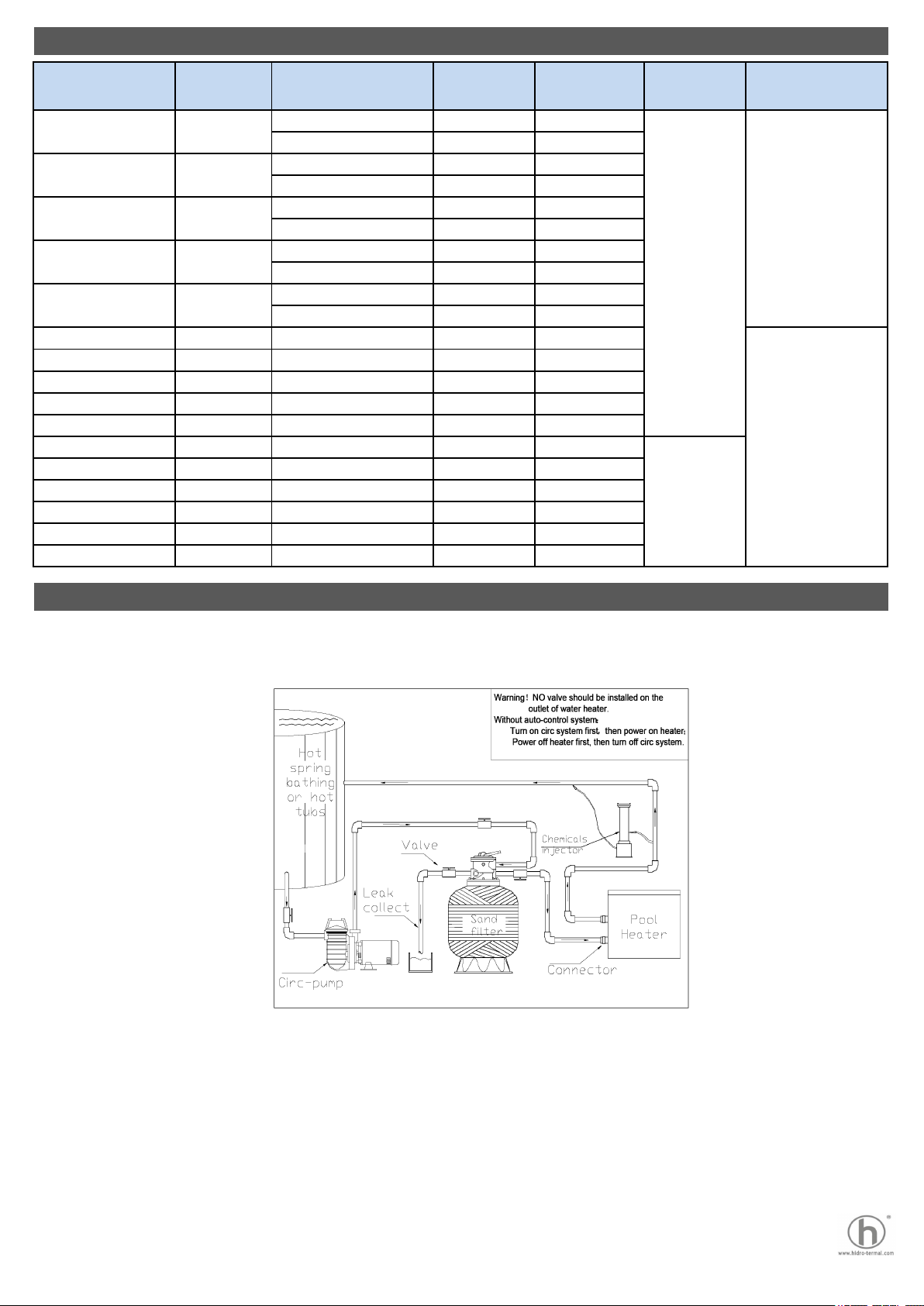
a.Check the circulation system first before turn on the heater.
b.Never disassemble the heater when connecting to power supply.
c.Never turn on the heater without water.
d.No power switch is designed for the heater. The front panel switch can only turn off the controller,
thus you should cut off the main power supply before performing maintenance or repair.
e.Proper grounding is important.
f.Start the circulation pump for at least 2 minutes before turn on the heater, and turn off the
circulation pump at least 2 minutes after turn off the heater.
g.Once unexpected high temperature 60 ℃ (140 ℉) occurs, the temperature switch cuts off the
system. You need to cut off the main power supply, resolve the fault and wait the temperature to fall
below normal temperature, then press the ‘Reset’ button to restart the heater.
1)Control system automatically heat-up procedure
Preparation stage
Once reconnected to power or if the water temperature is 1℃ below the user setting temperature at least 10
minutes after entering the waiting stage, the heater enters the preparation stage. Indicator 1 in Figure 10 blinks
shows that circulation pump is turned on for models with circulation pump control. ‘PUMP WORKING’ indicators
in Figure11 and Figure 12 turn on as well. If hint message ‘ PPc ’ does not appear on the panel within 2
minutes, and the water temperature is 1℃ below the user setting temperature after 2 minutes, the heater enters
next stage pre-heat stage.
Pre-heat stage
In this stage, heater heats up for 10 seconds and waits for 90 seconds. Indicator 1 in Figure 10 turns on for 10
seconds then blinks. ‘ Heating ’ indicators in Figure11 and Figure 12 turn on for 10 seconds as well. If hint
message ‘ HFL ’ does not appear on the panel and the water temperature is 1 ℃ below the user setting
temperature, heater enters next stage heat-up stage.
Heat-up stage
In this stage, all heating elements turn on, and heating indicator turns on as well. If hint message ‘FL’ does not
appear, heater will heat up to 1 ℃ above the user setting temperature, then heating indicator blinks for 2
minutes. After that, circulation pump turns off for models with circulation pump control. Heater enters next stage
waiting stage.
Waiting stage
Waiting stage lasts for at least 10 minutes. 10 minutes later, if the water temperature is 1 ℃ below the user
setting temperature, the heater jumps to preparation stage, otherwise, it remains in the waiting stage.
2)Control panel functions
▲ Increase the user setting temperature by 1℃ or 2℉.
▼ Decrease the user setting temperature by 1℃ or 2℉.
3)Switching button
a.Switch between temperature unit: Press # button for more than 3 seconds,panel displays ℃ and ℉ in turns.
Release the button once the unit you wish to choose appears, 5 seconds later, panel restore to display the
current water temperature.
b.Switch between temperature sensors: Press # button, the panel will blink and display temperature measured
by temperature sensor 2. After 5 seconds or press the # button again, panel will restore to display current water
temperature which is measured by temperature sensor 1.
9
NOTE
The automatically heat-up process is non-stopping and will continue to
circulating through all stages until the control system or heater is power off.