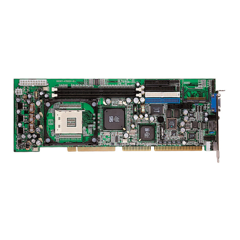
High Altitude Science Eagle Flight Computer User manual

Eagle Flight Computer
Manual
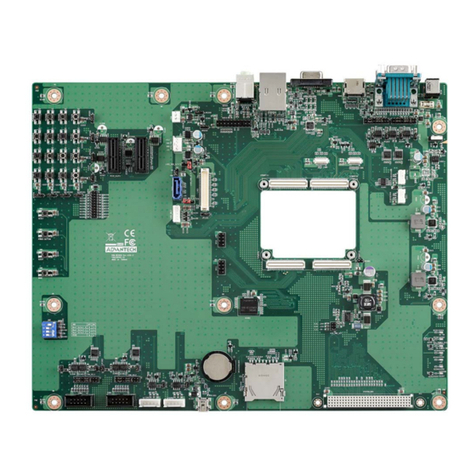
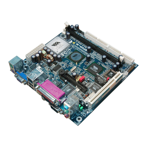
Sensor
Ports
Note: on bottom
side on newer
versions
System
LED
Servo Header
Note: Obsolete on
newer versions
Push
Button
Note: Obsolete on
newer versions
Micro
SD
Power
Terminal
GPS
Receiver

www.highaltitudescience.com Eagle Flight Computer Manual V1.0 –Page 2
Congratulations! You are the proud owner of what is currently the most powerful and robust flight computer
designed to operate at the very edge of space! This flight computer was designed using lessons learned from
working with computers onboard the International Space Station. It was also designed to meet military
specifications. That means your flight computer will reliably operate at temperatures as cold as –55 C or - 67 F.
To get the most out of your new flight computer, please take the time to become familiar with its features by
reading though this manual.
We test every flight computer before shipping it out. However, we still ask that you test your flight computer a
few days before every launch. If it doesn’t perform as expected, we will replace any flight computer with
manufacturing defects within a year of purchase.
GPS Receiver –Unlike most GPS receivers that cut out at 18,000 m ~ 60,000 ft due to military regulations, the
GPS receiver on your Eagle Flight Computer will continue to operate at altitudes of over 80,000 m ~ 260,000 ft.
Sensor Ports –There are multiple Sensor Ports that allow you to connect an assortment of sensor modules
developed by High Altitude Science to your flight computer. To make things easier, we use keyed connectors
so you don’t have to worry about connecting your sensor module backwards and destroying it. Once a sensor
module is connected, the computer will automatically detect it when you power it on.
Servo Header –On older versions, the servo header is used for transmitting APRS data via the Radio Bug. Since
the Radio Bug is now obsolete (The StratoTrack is more affordable and has greater capability), the servo
header has been dropped from the design as it was easy to damage.
Micro SD –All data from the flight computer is saved to a comma delimited .txt file on a micro SD card
allowing you to easily read your data and export it into a Microsoft Excel file for analysis. IMPORTANT: the
micro SD card must be 8 GB or smaller.
System LED –Think of it as your computer’s heartbeat. Even though it’s just one LED, it will give you a lot of
information once you know how to read it. It’s a super bright LED allowing you to easily confirm the correct
operation of your flight computer, even in direct sunlight.
Power Terminal –Allows you to connect your computer to any power source from 4.5 to 6.0 VDC. This means
you can power your computer with as little as 3 AA’s allowing you to save both weight and cost. A stress
release hole is also added at the base of the Power Terminal.
Why No Power Switch? –A power switch is a mechanical device with moving parts which makes it very
intolerant to large changes in temperature. By eliminating the power switch we removed a very common
failure point (especially at high altitudes) and made the flight computer significantly more reliable. If you know
how to solder, you are welcome to add your own power switch between the battery pack and flight computer.
Just make sure it is designed to operate at temperatures as cold as negative 60 C.

www.highaltitudescience.com Eagle Flight Computer Manual V1.0 –Page 3
Getting Started
Attaching the Power –Thread your power cable up through the stress relief hole.
Insert the wire ends into their appropriate slots and clamp in place by tightening
the power terminal screws with a flat-blade screwdriver. IMPORTANT: The black
wire goes into the slot marked “-“and the red wire goes into the slot marked “+”.
Failure to do so will damage your flight computer.
Attaching a Sensor Module - Insert the sensor wire harness plug into any Sensor
Port such that the clip on the wire harness plug engages with the lock on the data
port. The plug is keyed preventing you from plugging the sensor in backwards. The
computer will automatically detect the sensor when it is first powered on
regardless of which Sensor Port you connect it to. If you only wish to save GPS data
to your micro SD card, there is no need to attach a sensor. However, if you do
decide to attach a sensor module to either one of the Sensor Ports, it must be
attached before you power on the flight computer. On newer versions, the Sensor Ports are mounted to the
bottom side to protect them during rough landings.
Mounting the Micro SD –The flight computer will only save data to the micro SD card if it is properly
mounted. Once the computer has booted, data is saved to the micro SD card every six seconds. To mount your
micro SD card, slide it into the micro SD card slot on the bottom of the flight computer with the gold contacts
on the micro SD card facing up. The correct alignment of the micro SD card is printed on the top of the
computer. Once properly aligned, push your micro SD card into its slot until you hear a click. To remove your
SD card, push it until you hear a second click. You can now pull it out. IMPORTANT: the micro SD card must be
8 GB or smaller.
Powering On –Because the computer does not have a power switch, it will power on when the last battery is
inserted. The System LED will flash, indicating that the computer is powered. The first time your flight
computer is powered on, the GPS receiver will have to initialize before it achieves satellite lock. This may take
up to 10 minutes. Make sure your flight computer has an unobstructed view of the sky while initializing
(outside away from trees and buildings). The GPS receiver has a small LED. It will burn continuously while
initializing and searching for satellites. Once satellite lock is confirmed, the GPS receiver LED will start flashing.

www.highaltitudescience.com Eagle Flight Computer Manual V1.0 –Page 4
Reading the System LED
When the computer is first powered on, the System LED will flash to inform you that the computer has been
powered. Next the flight computer will boot, (approximately 10 –15 seconds), during which time the System
LED will not flash. After the flight computer successfully boots, the System LED will flash every time data is
saved or every six seconds. Every time data is successfully saved, it will either flash once, twice, or three times
to indicate how many sensors the computer has detected and is saving data from.
•One Flash Saving GPS data only (no sensor module detected).
•Two Flashes Saving GPS data and data from a single sensor module.
•Three Flashes Saving GPS data and data from two sensor modules.
IMPORTANT: If you forgot to insert your micro SD card before powering on your flight computer, the System
LED will flash continuously to warn you not to launch until the micro SD card is inserted. Once you insert the
micro SD card, wait a few seconds. The System LED will now start flashing every six seconds.
•Flashes Continuously No micro SD card detected.
IMPORTANT: In some instances, the System LED will only flash once every 30 seconds. This is to inform you
that the GPS receiver does not have valid clock data. Make sure your computer is outside and has a clear view
of the sky without buildings or trees obstructing its view. Also, make sure that there are no electronics that
could be potentially causing interference within close proximity of the computer.
Notes
GPS Receiver Interference –If you mount your flight computer inside a custom designed payload enclosure,
make sure that no metal objects, space blanket material, cameras, etc. are placed between the GPS receiver
and its view of the sky. Because your flight computer is designed to meet military specifications, it can be
mounted either externally or internally. No heat packs are required.
Using Your Flight Computer with a Tracking Device - Although some customers have concerns about placing
their flight computer in close proximity to a SPOT satellite tracker, we have never observed any interference
caused by placing a satellite tracker adjacent to the Eagle Flight Computer. As always, verify that all aspects of
your payload work simultaneously before launching. Never use a tracking device that broadcasts a signal over
a cellular network, whether it is a cell phone or any such device that transmits over a cellular network. Doing
so is illegal.
Choice of Batteries –IMPORTANT: High Altitude Science recommends using only Energizer Ultimate Lithium
AA batteries to power your flight computer. These are robust batteries designed to still maintain their voltage
at extremely low temperatures. Three of them will power your flight computer for well over 15 hours. Never
use alkaline batteries as they will fail to power your flight computer at cold temperatures.
How the Data File Works –Your flight data gets saved to a .txt file on your micro SD card. Data is always saved
to the same file. If the file already contains data when the computer is powered on, the computer will continue
to save data where it last left off. It will never delete old data. You can also remove the micro SD card from the
flight computer at any time without having to be concerned about losing or corrupting your data.

www.highaltitudescience.com Eagle Flight Computer Manual V1.0 –Page 5
Analyzing Your Data
Your data gets saved to a comma delimited .txt file on your micro SD card. To read the data, simply remove the
micro SD card from the flight computer (by pushing it in until you hear a click and releasing it), insert it into an
SD card adapter, and slide the SD card adapter into the SD slot found on most laptops. If your computer
doesn’t have an SD card reader, you can find micro SD to USB converters at most stores that carry digital
cameras. Navigate to the SD card on your computer and double-click on the .txt file. Your data should look
similar to the following:
Your data will have anywhere from two to four columns (the above example has three). The first column of
data is always GPS data. The last column is always Computer Health data that we at High Altitude Science use
internally to trouble shoot your computer in the unlikely event that it experiences an in-flight failure.
Depending on whether you connect one or two sensor modules to the Sensor Ports, you will have either one
or two columns of sensor data between the GPS and Computer Health data.
Transferring Your Data into a Microsoft Excel File
1. Open a new file in Microsoft Excel.
2. Go to File and click Open.
3. Select All Files in the Files of Type drop down menu.
4. Navigate to your .txt file, select it, and click Open. This will open the Text Import Wizard window.
5. Make sure Delimited is selected and click Next.
6. Under the Delimiters menu select Comma only.
7. Click Finish. All your data will now neatly appear in their own separate rows and columns in a
Microsoft Excel file.
Basic Trouble Shooting
If the System LED never flashes after powering on the flight computer:
1. Verify the batteries are inserted into the battery pack correctly.
2. Verify all connections between the battery pack and the flight computer.
3. Verify that you connected the black wire to the “-“terminal and the red wire to the “+” terminal.
4. Verify that you are using fresh batteries.
If the System LED only flashes once or twice every six seconds even though one or two sensors are connected
to the sensor ports:
1. Verify all connections between the sensors and the flight computer.
2. Unpower the flight computer and power it back on with the sensors connected. The flight computer
will not detect any sensors if they are connected after the flight computer is powered on.

www.highaltitudescience.com Eagle Flight Computer Manual V1.0 –Page 6
If the System LED only flashes only once every 30 seconds.
1. Verify your computer has been outside for a few minutes with a clear view of the sky (no buildings or
trees obstructing its view).
2. Verify that there are no electronics that could be potentially causing interference within close
proximity of the computer.
Pre-Launch Check List
Before powering on the flight computer, check that:
1. Power connections between the battery pack and flight computer are secure.
2. Red wire goes to “+” and black wire goes to “-“.
3. Sensor module(‘s) are securely connected to the Sensor Ports.
4. Micro SD card is fully seated.
5. Fresh lithium batteries are inserted into battery pack with correct orientation.
Wait for the computer to boot (10 to 15 seconds after powering on), and check that:
6. System LED is flashing every six seconds.
7. System LED is correctly indicating the number of sensor modules connected by:
▪Flashing once every six seconds if no sensor modules are connected
▪Flashing twice every six seconds if one sensor modules is connected
▪Flashing three times every six seconds if two sensor modules are connected.
8. GPS receiver has satellite lock.
▪Indicated by GPS receiver LED flashing (may have to wait a few minutes).
Congratulations! Your flight computer is now ready to fly!
IMPORTANT
Never fly near populated areas and major airports.
Always follow FAA regulations and remember that weather balloons and payloads are not toys and can be
dangerous if not prepared and used properly.
In no event shall High Altitude Science be liable for any direct, indirect, punitive, incidental, and/or special
consequential damages whatsoever arising out of or connected with the use or misuse of its products. The
buyer assumes all risk and liability resulting from ANY use of all products sold by High Altitude Science. Your
purchase and use of any High Altitude Science product constitutes your agreement to and acceptance of these
terms. If you do not agree to these terms and conditions, you must return the unused product in resalable
condition for a refund or credit.
Table of contents
