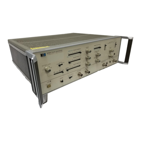
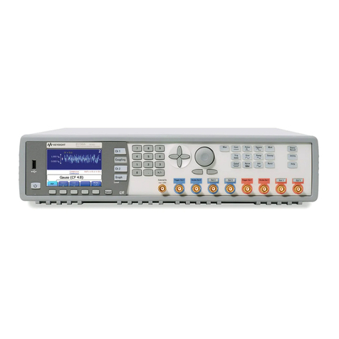
Highland P400 User manual

HIGHLAND TECHNOLOGY
Model P400
Benchtop Digital Delay/
Pulse Generator
Technical Manual

Copyright © 2005-2011 Highland Technology
18 Otis Street, San Francisco, CA 94103
Phone 415-551-1700 • Fax 415-551-5129
NOTICE
HIGHLAND TECHNOLOGY, INC. PROVIDES THIS PUBLICATION “AS IS”
WITHOUT WARRANTY OF ANY KIND, EITHER EXPRESS OR IMPLIED,
INCLUDING, BUT NOT LIMITED TO, THE IMPLIED WARRANTIES OF
MERCHANTABILITY OR FITNESS FOR A PARTICULAR PURPOSE.
(Disclaimer of expressed or implied warranties in certain transactions is not
allowed in some states. Therefore, the above statement may not apply to you.)
This manual may contain technical inaccuracies and/or typographical errors.
Changes are periodically made to this manual which are incorporated in later
editions. Highland Technology, Inc. may make changes and improvements to the
product(s) and/or programs described in this publication at any time without notice.
The P400 has finite failure rates associated with its hardware, firmware, design, and
documentation. Do not use the product in applications where a failure or defect in the
instrument may result in injury, loss of life, or property damage.
IN NO EVENT WILL HIGHLAND TECHNOLOGY, INC. BE LIABLE FOR
DAMAGES, INCLUDING LOST PROFITS, LOST SAVINGS OR OTHER
INCIDENTAL OR CONSEQUENTIAL DAMAGES ARISING OUT OF THE USE
OF OR INABILITY TO USE SUCH PRODUCT, EVEN IF HIGHLAND
TECHNOLOGY, INC. OR AN APPROVED RESELLER HAS BEEN ADVISED
OF THE POSSIBILITY OF SUCH DAMAGES, OR FOR ANY CLAIM BY ANY
OTHER PARTY.

Table of Contents
1Introduction and Scope ..........................................................................1
1.1 Scope .....................................................................................................1
1.2 Introduction.............................................................................................1
1.3 Operating And Safety Precautions .........................................................2
2Specifications..........................................................................................3
3Theory of Operation................................................................................7
3.1 Basic Timing ...........................................................................................7
3.2 Block Diagram and Basic Functions .......................................................8
4Quick Start: Pulse-Train Example .......................................................11
5Operating Instructions..........................................................................14
5.1 Front- and Rear-Panel Overview ..........................................................14
5.2 Help Mode ............................................................................................17
5.3 Menu Navigation...................................................................................17
5.4 Gate Menu............................................................................................18
5.5 Trigger Menu ........................................................................................ 19
5.6 Channel T0 Menu .................................................................................20
5.7 Channel A through D Menus ................................................................21
5.8 Auxiliary Menu ...................................................................................... 22
5.9 Store and Recall Menus .......................................................................23
5.10 Power-Up States ..................................................................................25
5.11 High Voltage Option .............................................................................25

6Typical Performance.............................................................................29
6.1 Typical Jitter Performance ....................................................................31
7Remote Programming........................................................................... 32
7.1 P400 Commands..................................................................................32
7.2 Remote Error Codes.............................................................................48
7.3 Command Strings................................................................................. 50
7.4 RS-232 Interface ..................................................................................51
7.5 Ethernet Interface .................................................................................52
7.5.1 DHCP-Mode Configuration ......................................................52
7.5.2 Static-Mode Configuration........................................................ 53
7.5.3 Connecting the P400 to the Network........................................ 53
8Versions, Options, and Accessories...................................................55
9Index.......................................................................................................56

Table of Figures
Figure 1. Example Timing Diagram.......................................................................7
Figure 2. Block Diagram .......................................................................................8
Figure 3. Pulse-Train Example Timing................................................................12
Figure 4. Front Panel ..........................................................................................14
Figure 5. Rear Panel...........................................................................................16
Figure 6. Gate Menu ...........................................................................................18
Figure 7. Trigger Menu ....................................................................................... 19
Figure 8. Channel T0 Menu ................................................................................20
Figure 9. Channel A through D Menus................................................................21
Figure 10. Auxiliary Menu ................................................................................... 22
Figure 11. Store Menu ........................................................................................23
Figure 12. Recall Menu....................................................................................... 24
Figure 13. High Voltage Option Block Diagram .................................................. 26
Figure 14. Pulse width as a function of output .................................................... 26
Figure 15. Duty Cycle .........................................................................................27
Figure 16. Pulse rise and fall times.....................................................................27
Figure 17. Typical 50-volt output pulse ...............................................................28
Figure 18. Typical Output Waveforms.................................................................29
Figure 19. 10 V Pulse with High-Impedance Termination ................................... 30
Figure 20. RS-232 Connector Pin-Out ................................................................51
Table of Tables
Table 1. P400 Specifications ................................................................................3
Table 2. Front-Panel Features ............................................................................ 15
Table 3. Back-Panel Features ............................................................................ 16
Table 4. P 400 Commands .................................................................................33
Table 5. Remote Error Codes .............................................................................49
Table 6. Examples of Command Strings.............................................................51
1
1ntroduction and Scope
1.1
Scope
This document is the technical manual for the Highland Technology Model P400
benchtop digital delay generator, Highland part number 23A400-1.
1.2
ntroduction
The P400 is a versatile, four-channel digital delay and pulse generator. The unit
supports five trigger sources.
Internal direct digital synthesis (DDS) rate generator
External logic input
Line input (via external adaptor)
Remote serial input
Manual pushbutton
Any of these five trigger sources can be gated by an external signal. Each of the four
channels can be programmed to trigger on the leading or trailing edge of any other
channel, or on the leading edge of the trigger. Channel timings can be specified as
an initial delay and pulse-width or as a pair of leading and trailing edge-delays. In
both modes, the resolution is one picosecond and the timing cycle must complete
within 999.999… seconds of the start of the cycle.
In addition to programming the edge timings, the following parameters may be set
independently for each channel:
VH (pulse high) and VL (pulse low) levels
Pulse polarity

2
1.3
Operating And Safety Precautions
When using AC-line power, use only the external AC adaptor furnished with the
P400. (See page 3 for power specifications.)
Do not apply potentials to any P400 outputs.
Do not apply more than ±5 volts to the TRIGGER input.
Do not apply more than 0 to +5 volts to the GATE or CLOCK connectors.
The high-speed semiconductors used in the P400 are necessarily static sensitive.
Use standard antistatic precautions when using the P400.
During powerup and powerdown, it is possible that the P400 may create undesired
outputs at the T0, A, B, C, D, or GATE outputs. Do not use the P400 in situations
where such outputs may result in compromises in personnel safety or equipment
damage.

3
2Specifications
Table 1. P400 Specifications
FUNCTION Four-channel digital delay and pulse generator
Independently programmable delay/pulse
width/polarity/high level/low level on all four delay
outputs A, B, C, and D
CHANNELS Four outputs of programmable delay, pulse width,
polarity, and voltage levels
TRIGGER SOURCES Internal DDS synthesizer, external source, AC line with
external transformer adaptor, remote command, and
manual pushbutton
TRIGGER RATE 10 MHz maximum
EXTERNAL TRIGGER
INPUT
Programmable threshold: -2.4 to +4.6 V
Programmable slope
Programmable termination: 50 Ωor 1 MΩ
Minimum pulse width: 2 ns at 0 to 2 V (25 ns in burst
mode)
LINE TRIGGER INPUT 3-24 VRMS using external AC adaptor
DDS TRIGGER RATE 0.01 Hz to 10 MHz in 0.01 Hz steps
PULSE OUTPUTS (A TO
D AND T0)
V
OH
programmable -4.3 to +11.8 V
V
OL
programmable -5.0 to +4.1 V
0.1 V steps, 50Ωsource impedance
4 V/ns slew rate
INSERTION DELAY 25.0 ns ±500 ps
DELAY RESOLUTION 1 ps, delay or width of A,B,C,D outputs

4
DELAY RANGE 999.999999999999 seconds, delay or width of A, B, C,
D outputs, total delay + width not to exceed
999.999999999999 seconds
A to D timings are relative to T0 rising edge
DELAY ACCURACY T0, rises 25 ns ± 500 ps after trigger
A to D outputs, ± 400 ps ± timebase error
A to D delay and width edges are monotonic to 50 ps
JITTER T0, 20 ps RMS max from external trigger
A to D outputs (25 ps RMS + timebase jitter) max, either
edge from external trigger or any other output
GATE INPUT V
IH
: +3.5 V min, +6 V max
V
IL
: -0.5 V min, +1.5V max
Programmable active high/low
GATE OUTPUT V
IH
: +5 V typ, V
IL
: 0 V typ
50 Ωsource impedance, programmable active high/low
10 MHZ CLOCK INPUT V
IH
: +3.5 V min, +6 V max
V
IL
: -0.5 V min, +1.2 V max
0.7 V min hysteresis
10 MHZ CLOCK OUTPUT V
OH
: +5 V typ, V
OL
: 0 V typ
50 Ωsource impedance
DDS OUTPUT Sine wave, 4 V p-p typical, 50 Ωsource impedance
COMMUNICATIONS Standard RS-232 with SCPI-like command set
Optional Ethernet using Telnet mode
Command set identical to RS-232 mode

5
INDICATORS 20-character by 4-line, alphanumeric display
LEDs indicate selected channel, activity, triggers,
communications, and errors
TIMEBASE Standard TCXO:
Initial calibration ±0.25 PPM
Drift <2 PPM/year
Temperature coefficient below 50 ppb/°C
Jitter below 2 ns per second of delay
Optional OCXO:
Initial calibration ±0.1 PPM
Drift <1 PPM/year
Temperature coefficient below 3.6 ppb/°C
Jitter below 400 ps per second of delay
Either oscillator can be phase-locked to an external 10
MHz source
PACKAGING 8" (W) x 12” (L) x 4.5" (H), exclusive of external power
module
Weight: 8 lbs
POWER 100 to 240 VAC, 47 to 63 Hz, 60 W max using AC
adaptor furnished
Operable from +24 VDC, 2.5 amps max via 2.5 mm x 5
mm female connector

6
OPTIONS Rear-panel transformer-isolated 5 to 50 V
programmable high-voltage pulse outputs
10BASE-T Ethernet
Ovenized oscillator timebase (OCXO)
Single/dual rackmount adaptors
OEM versions
CONFORMANCE Designed to meet UL/FCC/CE requirements

7
3Theory of Operation
3.1
Basic Timing
Figure 1 depicts the basic P400 timing cycle.
Figure 1. Example Timing Diagram
A timing cycle begins 25 ns after a trigger pulse is received. T0 is asserted,
transitioning from VL (programmed low level) to VH (programmed high level),
indicating the start of the timing cycle. After the initial delay, each channel’s output is
asserted, transitioning from VL to VH or VH to VL, depending on the output polarity.
Channel timing is relative to the leading edge of T0, not to the trigger pulse.
When the last channel is deasserted, the T0 output falls, transitioning from VH to VL.
At this point, end-of-delay (EOD) is declared and the internal EOD signal is asserted
for approximately 50 ns. During this time, all outputs are reset to their default state,
the 50 MHz oscillator is disabled, the HIT flip-flop is held in reset and the T0 output is

8
driven to VL. When the EOD interval expires the P400 is ready to accept new trigger
pulses.
If the last programmed edge is programmed to be k ns after T0, the P400 will accept
triggers separated by (k + 60) ns up to the specified 10 MHz max. For very short
programmed delays, the P400 will typically externally trigger above 13 MHz. .
3.2
Block Diagram and Basic Functions
Figure 2. Block Diagram
The P400 contains the following logic blocks and functions:
TRIGGER MULTIPLEXER. This circuit selects one of four possible trigger sources:
internal, external input, AC line input, or manual single-shot.
The internal trigger source is derived from the programmable DDS frequency
synthesizer. The DDS synthesizer can be programmed from 0.01 Hz to 10 MHz in
0.01 Hz steps.

9
The external trigger input is conditioned by a precision voltage comparator before
connecting to the TRIGGER MULTIPLEXER. The reference input of the comparator
is connected to a programmable voltage source. Trigger polarity and input
impedance are programmable.
All triggers can be gated on or off by applying an asynchronous TTL-level signal to
the GATE connector. In addition, both the internal and the external triggers can be
configured to pass nof mtriggers, thereby providing burst capability.
HIT FLIP-FLOP. The Hit Flip-Flop initiates the timing cycle and enables the main
timing oscillator. The output of the Hit Flip-Flop is connected through a driver to the
T0 output. The EOD logic clears the flip-flop when all channels have completed their
output pulses, preparing the P400 for a new timing cycle.
10 MHZ CLOCK. This temperature-compensated, crystal-controlled oscillator
(TCXO) is the timing reference for all delays. An optional ovenized oscillator (OCXO)
is also available. The OCXO is more stable over time and temperature than the
TCXO and contributes less jitter to long delays. The 10-MHz clock can be locked to
an external 10-MHz clock through the CLOCK connector on the back panel.
50-MHZ OSCILLATOR. This oscillator provides the coarse (20-ns granularity)
component of all delays. A DSP-based phase-lock system locks the 50-MHz
oscillator to the internal crystal-controlled 10-MHz clock, making the oscillator as
accurate as the clock while preserving phase coherency to the original trigger.
DIGITAL (COARSE) COUNTERS. The output of the 50-MHz oscillator is connected
to eight digital counters, two for each output channel. The first counter times the
leading edge of the pulse, the second counter times the trailing edge.
VERNIER DELAYS. A fine-resolution delay circuit follows each digital counter to
interpolate delays to 1-ps resolution. The output of each vernier delay is connected to
an output driver.
OUTPUT DRIVERS. Each of the four channels has a single output driver. The output
driver combines the leading-edge and the trailing-edge signals to produce a single
channel output. Each driver has programmable polarity, and high and low voltage
levels.
MICROPROCESSOR SYSTEM An internal 32-bit microprocessor subsystem
manages the P400. It interacts with the front-panel controls and displays and the
external RS-232 and Ethernet interfaces.

10
POWER SUPPLIES Voltage regulators generate the required internal voltages from
the 24 VDC input on the back panel. These regulators are typically powered by the
external, AC-powered, universal-input, switching power supply furnished with each
unit.

11
4Quick Start: Pulse-Train Example
1.
Basic operation of the P400 may be demonstrated using its default
configuration. To invoke this mode, turn the unit off, and then turn it back
on while holding the numeric "0" key down.
2.
When the trigger screen appears and "LOADING DEFAULT CONFIG" is
displayed, release "0.” Press the START button to begin pulsing.
The default setup enables internal triggering at 1.00 KHz. Channels A, B,
C, and D produce sequential 100 microsecond positive pulses, with
baselines of 0 volts and pulse height +4 volts into a high-impedance load.
3.
Connect an oscilloscope to the P400, with the T0 pulse applied to scope
Channel 1, and trigger on the rising edge of this signal.
4.
Connect available additional scope channels to P400 outputs A, B, C, and
D. Set the scope to 100 µsec/cm horizontal, 5v/cm vertical.
The scope display should look similar to that shown in Figure 3. The
traces are, from top to bottom, signals T0, A, B, C, and D. (Voltages are
not shown to scale in this figure.)

12
Figure 3. Pulse-Train Example Timing
One can now vary menu settings and observe changes in the scope display.
Some suggested operations to try are:
Push the STOP and RUN buttons to control pulsing off/on
Push the "A" button to bring up the Channel A display. Use the arrow keys to pan
the cursor to various control fields, then use the spinner knob to vary parameters
and observe the effects on the scope display.
Note that, if you change pulse delay or width such as to make the trailing edge of
the pulse exceed 500 µs after trigger, the T0 pulse width will extend to track the
Channel A falling edge, demonstrating that the P400 timing cycle runs until all
channels are done.
Push the TRIG button and pan the cursor to the 100 Hz digit of the trigger rate
field. Use the spinner or the numeric keypad to alter the trigger rate. Note that as

13
you set the trigger rate above 2 KHz, the P400 will begin missing triggers, and the
"RATE" LED will illuminate, because the unit is receiving triggers before the
previous timing cycle is completed.
Push the HELP button, then scroll through the Help text using the spinner knob.
While in Help mode, you can press any other button to jump to the section of text
that explains that function. Press HELP again to return to normal mode.

14
5Operating nstructions
5.1
Front- and Rear-Panel Overview
The front panel is shown in Figure 4 and described in Table 2.
START STOP STORE RECALL HELP AUX
CLR ENTER0
7 98
4 65
1 32
RUN REMOTERATE
POWER
HIGHLAND TECHNOLOGY
MODEL P400 DIGITAL DELAY GENERATOR
GATE TRIG T0 ABCD
sec milli micro nano pico
2
1
3
4
5
8 9
12
1318
19
20
17
14
16
15
6 7
11
10
Figure 4. Front Panel

15
Table 2. Front-Panel Features
1
20
-
Character by 4
-
Line Display
P400 operator interface display
2
Time Display Labels
These identify engineering unit positions in time displays
3
START and STOP Keys
Start and stop triggering or manually trigger a delay, indicated by the
adjacent red/green LED The P400 always powers up in the STOP state.
4
Activity LEDs
These indicators light when the associated function is active
5
Menu Keys
These keys select the gate, trigger, and channel menus
6
Gate Connector
Gates the trigger source
7
Trigger Connector
Input for an external trigger source to the P400
8
STORE and RECALL Menu Keys
These keys store and recall P400 configurations
9
Channel Connectors
Outputs of the T0, A, B, C, and D channels
10
POWER Button
This button turns the P400 on and off
11
Scroll Keys
Provide navigation through the menus
12
Spinner Knob
Rotating this knob changes menu items. Pressing and rotating the knob
allows movement through a menu
13
AUX Menu Key
This key displays the auxiliary menu
14
ENTER Key
Accepts numeric values
15
REMOTE LED
This LED flashes when the P400 is accessed remotely
16
RATE LE
D
This LED flashes when trigger rate is incompatible with delay settings
17
RUN LED
This LED lights when a timing cycle is active
18
HELP Menu Key
Displays the Help menu
19
CLR Key
Clears the digits at and to the right of the cursor
20
Numeric
Keypad
Enters numbers in delay, width, voltage and frequency menu items or
selects a memory location in the store and recall menus
Table of contents
Popular Pulse Generator manuals by other brands

Honeywell
Honeywell IN-S Series instruction manual

Tektronix
Tektronix PG 509 instruction manual

Tektronix
Tektronix PG 501 instruction manual

DEI
DEI PCX-7420 Operation manual

AVTECH ELECTROSYSTEMS LTD.
AVTECH ELECTROSYSTEMS LTD. AVRQ-5-B instructions

AVTECH ELECTROSYSTEMS LTD.
AVTECH ELECTROSYSTEMS LTD. AVL-AV-1-W-B instructions