DEI PCX-7420 User manual

PCX-7420 B
Pulsed Current Source
Operation Manual
Directed Energy, Inc.
1609 Oakridge Dr., Suite 100, Fort Collins, CO 80525 (970) 493-1901
sales@directedenergy.com
www.directedenergy.com
Document #7650-0037, Rev. A2
© Copyright 2019, Directed Energy, Inc. All rights reserved.


Contents
Safety .............................................................................. 4
Introduction .................................................................... 5
Description .................................................................................................... 5
Panel Layout .................................................................................................. 6
Front Panel Features ..................................................................................... 7
Rear Panel Features ...................................................................................... 8
Accessories Included ................................................................................... 9
Operation ...................................................................... 11
Setup............................................................................................................ 11
Power Up ..................................................................................................... 11
Set the Main Output Current ....................................................................... 11
Set the Bias Output Current ....................................................................... 12
Set the Main Pulsewidth .............................................................................. 12
Set the Bias Width ....................................................................................... 13
Set the Trigger Type .................................................................................... 13
Set the Termination ..................................................................................... 14
Set the Frequency ....................................................................................... 15
View Information About the PCX-7420 B ................................................... 15
Save Settings ............................................................................................... 16
Recall Settings ............................................................................................ 16
Warnings and Faults .................................................................................... 17
View the Communication Settings .............................................................. 18
Power Down ................................................................................................. 18
Command Set ............................................................... 19
Warranty and Service .................................................. 25
Factory Service and Support ...................................................................... 25
CE Declaration .............................................................. 26

Page 4 of 28
Document #7650-0037 Rev A2. © Copyright 2019 Directed Energy, Inc. All rights reserved.
Safety
• Do not open the cover of PCX-7420 B. There are no user-serviceable parts
inside. Opening the cover exposes you to lethal shock and voids the factory
warranty.
• Do not install, handle, or remove the output cable or laser diode while the PCX-
7420 B is operating.
• The PCX-7420 B can be triggered randomly by spurious transients. Always
assume it is possible to get an unexpected pulse at the output.
• Allow at least 10 minutes after power-down before handling the output cable
or laser diode.
• Do not use this device in a manner not specified by the manufacturer.
• Allow sufficient space around this device for air circulation. Cooling air enters
the front of the chassis and exits the back of the chassis.
• Take normal precautions to protect this device against liquid entry or
corrosive environments.
• Clean this device by wiping with a dry or damp cloth.
WARNING
Risk of lethal electric shock. Do not open the cabinet of this
device. Do not touch the output or laser diode while it is
operating. This device produces LETHAL levels of electrical
current, both inside its cabinet and at its output.
DO NOT OPERATE THIS DEVICE UNLESS ANOTHER PERSON
CAPABLE OF RENDERING FIRST AID OR RESUSCITATION IS
PRESENT.
SAFE AND PROPER OPERATION OF THIS DEVICE IS THE
RESPONSIBILITY OF THE USER.
Directed Energy, Inc. (DEI) provides information on its products and
associated hazards, but it assumes no responsibility for the after-sale
operation and safety practices.

Page 5 of 28
Document #7650-0037 Rev A2. © Copyright 2019 Directed Energy, Inc. All rights reserved.
Introduction
Description
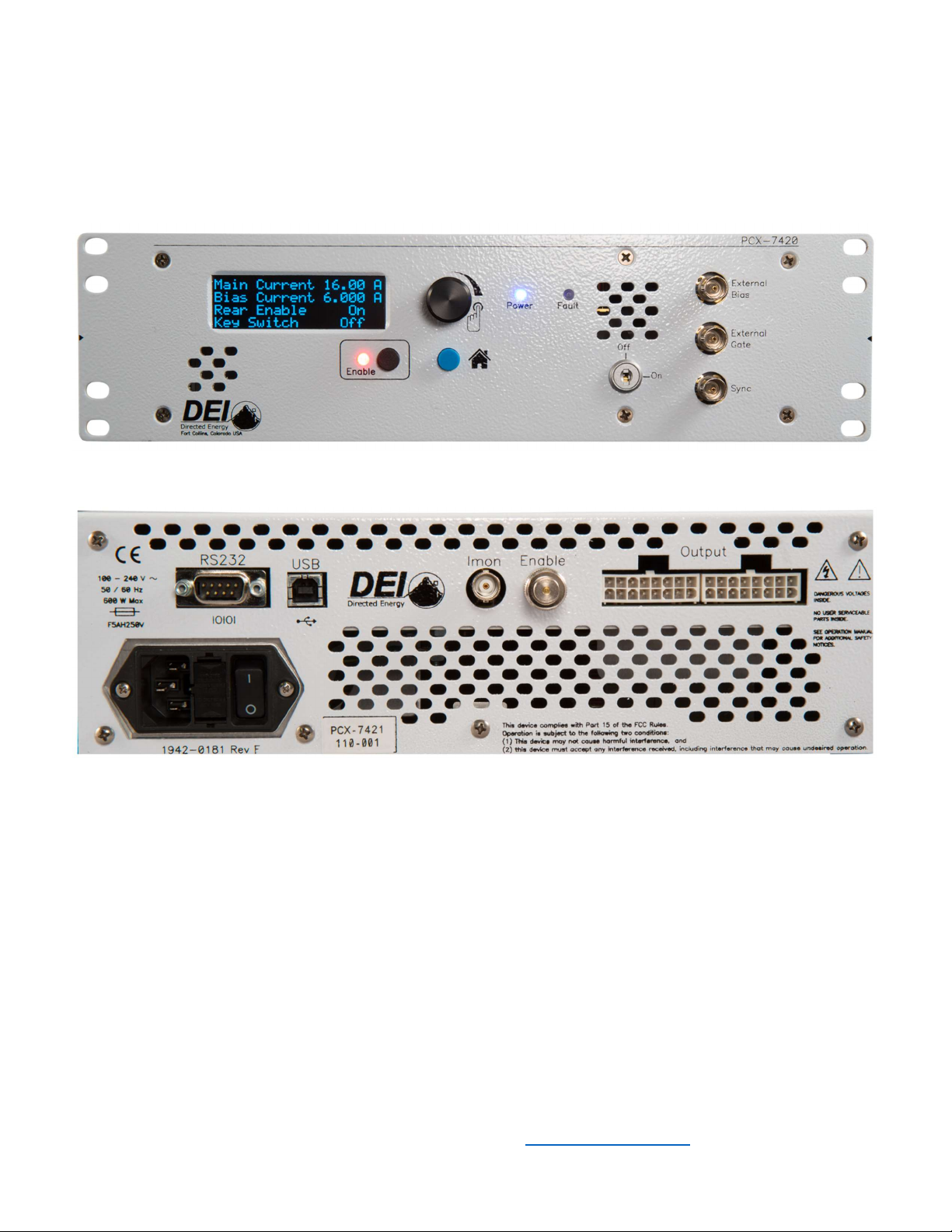
The PCX-7420 B is a pulsed current source designed to drive laser diodes, bars,
and arrays. It delivers current pulses from 3 A to 21.5 A with up to 250 W of total
output power. An internal trigger source provides pulse repetition frequencies from
40 Hz to 100 kHz. The external trigger function allows operation at frequencies
from single-shot to 1 MHz.
The bias current amplitude, main output current amplitude, bias pulse width, main
pulse width, trigger source, and trigger frequency are adjustable from the front
panel OLED screen or by computer control via RS-232 or USB interface.
The bias feature allows the PCX-7420 B to deliver a current pulse in two steps.
The first step—the bias pulse—starts before the intended trigger time. Current is
set just below the lasing point, minimizing the diode’s response time to the main
pulse. The bias pulse current is adjustable from 0 A to 5.8 A and the pulse width
is adjustable from 0 ms to 25 ms.
The main pulse current adds to the bias current and energizes the diode at the
intended time. The main pulse current is adjustable from 3 A to 15.7 A and the
pulse width is adjustable from 50 ns to 5 ms.
Note: The total current output pulse is always the sum of the bias pulse current
and the main pulse current, even if the bias pulse width is set to zero. Consider
both the bias output current and the main output current when planning the total
output current.
The PCX-7420 B can be triggered internally or externally. The input termination
impedance for both the external gate and the external bias gate is selectable for
either 50 Ω or 10000 Ω. The Sync output signal on the front panel allows the PCX-
7420 B to be synchronized with other devices. The Sync signal logic levels are 0
V and +5 V, and its rising edge corresponds to the rising edge of the main output
current pulse. The delay between the Sync output signal and the main output
current pulse is 5 ns to 15 ns.

Page 6 of 28
Document #7650-0037 Rev A2. © Copyright 2019 Directed Energy, Inc. All rights reserved.
Panel Layout
All features of the front and rear panel are labeled. Their functions are covered in
the next section.

Page 7 of 28
Document #7650-0037 Rev A2. © Copyright 2019 Directed Energy, Inc. All rights reserved.
Front Panel Features
HOME Button
Returns the PCX-7420 B front-panel display to the HOME screen. (The HOME screen
contains the Main Current, Bias Current, Rear Enable status, and Key Switch status.)
ENABLE Button
Toggles the PCX-7420 B between enabled and disabled. The button illuminates green
when the unit is enabled and red when disabled.
OLED Screen
Provides a user interface to the PCX-7420 B.
Encoder Knob
Changes screens on the front panel and changes the values of parameters. Rotate to
change a value; push to cycle through the resolutions (increments of value change).
When finished changing the parameter, press HOME to exit the parameter screen.
Keyswitch
Allows the PCX-7420 B to be enabled when ON. Disables the PCX-7420 B and
prevents the system from being enabled when OFF.
External Bias Input
Accepts bias trigger pulses from an external source via a BNC connector.
External Gate Input
Accepts trigger pulses from an external source via a BNC connector.
Note: The impedance of the External Bias input and the External Gate input are
selectable to either 50 Ω or 10 kΩ simultaneously.
Sync Output
Provides synchronizing output pulses to an external device via a BNC connector. The
sync pulse is coincident with the leading edge of the output current pulse.

Page 8 of 28
Document #7650-0037 Rev A2. © Copyright 2019 Directed Energy, Inc. All rights reserved.
Rear Panel Features
Output
Accepts the factory-supplied output cable and provides the generated current pulses.
DO NOT TOUCH any part of this cable while the PCX-7420 B is powered up. Please
review the Safety section above.
Rear Enable
Accepts either an external dry-contact closure or the factory-supplied shorting BNC
plug. Closing the contacts, or installing the shorting plug, enables the output. Opening
the contacts, or removing the shorting plug, disables the output and creates a rear
enable fault.
IMON Output
Provides a voltage signal to an oscilloscope via a BNC connector that is proportional
to the output current. Scaling is 36 mV / 1 A into 50 Ω.
NOTE: NEVER connect an oscilloscope directly to the output of the system.
USB Cable Connector
Provides communication with an external computer via USB.
RS-232 Cable Connector
Provides communication with an external computer via an RS-232 null cable.
Power Cable Connector
Accepts a standard grounding equipment power cable.
Fuse Holder
Houses two AC power fuses.
On-Off Switch
Powers the PCX-7420 B ON and OFF.

Page 9 of 28
Document #7650-0037 Rev A2. © Copyright 2019 Directed Energy, Inc. All rights reserved.
Accessories Included
AC Power Cable
Factory-supplied standard computer-style power cord with NEMA C14 and NEMA 5-
15R connectors.
Shorting BNC Plug
Attaches to the Rear Enable BNC connector. Enables the output when a closed-
contact system is not used.
Keyswitch Keys
Keys for the front-panel keyswitch that allows the output to be enabled.
Output Cable
Two (2) factory-supplied cables that provide high current pulses to the external device.
Output Cable Pinout Information
The two male Amp connectors interface with the instrument and have the following
pinout on each connector:
Pins 1 through 8: negative (‒) output
Pins 9 through 16: positive (+) output
Rear view of Amp 770583-1 connector showing pinout

Page 10 of 28
Document #7650-0037 Rev A2. © Copyright 2019 Directed Energy, Inc. All rights reserved.
Laser Output PCBA
A factory-supplied laser output circuit board that provide a simple method to interface
a laser or other external device.

Page 11 of 28
Document #7650-0037 Rev A2. © Copyright 2019 Directed Energy, Inc. All rights reserved.
Operation
Setup
1.
Make sure the PCX-7420 B has been OFF for at least ten minutes.
2.
Make sure the polarity of the diode connection is correct. If necessary,
review the
output cable pinout in the Specifications section.
3.
Connect the output cable from the PCX-7420 B to the output device.
4.
Make the other connections (not required): External Trigger, External Bias, Sync,
IMON, and a connection to the computer.
5.
Connect the Rear Enable BNC and power cable.
Power Up
1.
Turn the power switch ON (I).
The unit displays the system
information, serial number and
firmware revisions as the unit
initializes.
The Home screen displays Main
Current, Bias Current, Rear
Enable, and Key Switch when the
system has finished initializing.
2.
Turn the keyswitch ON when ready to
turn on the output pulse.
Set the Main Output Current
MAIN:CURRENT:SETPOINT?
MAIN:CURRENT:SETPOINT n
1.
Rotate the encoder knob until Main
Current is displayed on the screen.
2.
Press the encoder knob to update the
main output current.
PCX
-
7420 B
--------
Serial # 110-001
Firmware D03-P05
Main Current 11.23 A
Bias Current 1.234 A
Rear Enable On
Key Switch Off
Main Current
------------
11.234 A
Press KNOB to update

Page 12 of 28
Document #7650-0037 Rev A2. © Copyright 2019 Directed Energy, Inc. All rights reserved.
3.
Rotate the encoder knob to change the value. The range is 3 A to 15.7 A.
4.
Press the encoder knob to change the multiplier to x0.001, x0.010, x0.100,
x1.000, or x10.000 indicated by the
asterisk (*).
5.
When the correct value is displayed,
press the Home button.
Set the Bias Output
Current
BIAS:CURRENT:SETPOINT?
BIAS:CURRENT:SETPOINT n
1.
Rotate the encoder knob until Bias
Current is displayed on the screen.
2.
Press the encoder knob to update the
bias current.
3.
Rotate the encoder knob to change
the value. The range is 0 A to 5.8 A.
4.
Press the encoder knob to change the
multiplier value to x0.001, x0.010,
x0.100, or x1.000 indicated by the
asterisk (*).
5.
When the correct value is displayed,
press the Home button.
Set the Main Pulsewidth
TRIG:INT:MAIN:PULSEWIDTH?
TRIG:INT:MAIN:PULSEWIDTH n
1.
Rotate the encoder knob to the Main Pulsewidth screen.
2.
Press the encoder knob to update the
pulse width.
3.
Rotate the encoder knob to change
the value. The range is 0.100 µs to
5000 µs.
4.
Press the encoder knob to change the
multiplier value to x25 ns, x100 ns,
x1.000 µs, x10.000 µs, or x100.000
µs.
5.
When the correct value is displayed,
press the Home button to return to
the Home screen.
Main Current
------------
11.234 A
*
Bias Current
------------
1.234 A
Press KNOB to update
Bias Current
------------
1.234 A
*
Main Pulsewidth
---------------
0.009,500 ms
Press KNOB to update
Main Pulsewidth
---------------
0.009,500 ms
x100.000 us

Page 13 of 28
Document #7650-0037 Rev A2. © Copyright 2019 Directed Energy, Inc. All rights reserved.
Pulse width resolution, internal 40 Hz to 300 Hz: 6400 ns
300 Hz to 5000 Hz: 1600 ns
5 kHz to 100 kHz: 100 ns
For external settings:
1.
Set the Pulse Width on the external signal generator.
Set the Bias Width
TRIG:INT:BIAS:PULSEWIDTH?
TRIG:INT:BIAS:PULSEWIDTH n
1.
Rotate the encoder knob to the Bias
Pulse Width screen.
2.
Press the encoder knob to update the
bias pulse width.
3.
Rotate the encoder knob to change
the value. The range is 0 µs to 25000
µs.
4.
Press the encoder knob to change
the multiplier value to x25 ns, x100 ns,
x1.000 µs, x10.000 µs, or x100.000 µs.
5.
When the correct value is displayed, press the Home button to return to the
Home screen.
Pulse width resolution, internal 40 Hz to 300 Hz: 6400 ns
300 Hz to 5000 Hz: 1600 ns
5 kHz to 100 kHz: 100 ns
For external settings:
1.
Set the Bias Pulse Width on the external signal generator.
Set the Trigger Type
Set the Source
TRIG:INTERNAL
TRIG:EXTERNAL
When the trigger source is set to
Internal, the second screen from Home
will display the frequency and pulse
width values. When the trigger source
is set to External Gate, the second
screen will only display the External
Bias Pulsewidth
---------------
0.000,500 ms
Press KNOB to update
Bias Pulsewidth
---------------
4.009,500 ms
x10.000 us
Trigger External
Bias & Gate
Termination 50 ohm
Trigger Internal
Frequency 100 kHz
Main Pulse 9.500 us
Bias Pulse 0.500 us

Page 14 of 28
Document #7650-0037 Rev A2. © Copyright 2019 Directed Energy, Inc. All rights reserved.
Gate information. It is recommended to
disable the system prior to switching
between internal and external
triggering.
1.
Rotate the encoder knob to the
Trigger Type screen.
2.
Press the encoder knob to select the
Trigger Type.
3.
Rotate the encoder knob between
Internal and External Gate.
4.
When the correct Trigger Type has
been selected, press the Home button
to return to the Home screen.
Set the Termination
TRIG:EXT:TERM?
TRIG:EXT:TERM n
1.
If you selected External Trigger, the
correct termination must be set.
2.
Rotate the encoder knob to the Trigger
Termination screen.
3.
Press the encoder knob to select the
termination value.
4.
Rotate the encoder knob between 50
Ω and 10 kΩ.
5.
Press the Home button to return to the
Home screen.
Trigger Type
------------
Internal
Press KNOB to update
Trigger Type
------------
** Internal **
External Gate
Termination
-----------
50 ohm
Press KNOB to update
Termination
-----------
** 50 ohm **
10k ohm

Page 15 of 28
Document #7650-0037 Rev A2. © Copyright 2019 Directed Energy, Inc. All rights reserved.
Set the Frequency
TRIG:INT:FREQ?
TRIG:INT:FREQ n
When changing the frequency, the PCX-7121 maintains the duty cycle. It is
recommended to change the frequency and then the pulse width.
For internal settings:
1.
Rotate the encoder knob to the
Frequency screen.
2.
Press the encoder knob to change the
frequency.
3.
Rotate the encoder knob to select a
value between 40 Hz and 100000 Hz.
4.
Press the encoder knob to change the
multiplier value to x1, x10 x100,
x1000, or x10000, indicated by the
asterisk (*).
5.
When the correct value is displayed,
press the Home button to return to the Home screen.
Pulse width resolution, internal 40 Hz to 300 Hz: 1 Hz
300 Hz to 5000 Hz: 100 Hz
5 kHz to 100 kHz: 1000 Hz
For external settings:
1.
Set the Frequency on the external signal generator.
View Information About the PCX-7420 B
*IDN?
1.
On the Home screen, rotate the
encoder knob counter-clockwise 1
screen.
2.
The About screen appears. View the
model number, serial number, and
firmware revision level.
3.
Press the Home button to return to the
Home screen.
Frequency
---------
100,000 Hz
Press KNOB to update
Frequency
---------
100,000 Hz
*
PCX-7420 B
--------
Serial # 110-001
Firmware D03-P05

Page 16 of 28
Document #7650-0037 Rev A2. © Copyright 2019 Directed Energy, Inc. All rights reserved.
Save Settings
*SAVE n
1.
Rotate the encoder knob to the Save
Settings screen.
2.
Press the encoder knob to enter the
save menu.
3.
Rotate the encoder knob to choose a
memory location from 1 to 5. During
power up, the system defaults to
memory location 1 parameters.
4.
Press the encoder knob to save the
values in the chosen memory location.
The screen will display “Saving to
location # n”, indicating the data is
being saved.
5.
After the parameters have been saved
to memory, press the Home button to return to the Home screen.
Recall Settings
*RECALL n
1.
Rotate the encoder knob to the Recall
Settings screen.
2.
Press the encoder knob to enter the
Recall Settings menu.
3.
Rotate the encoder knob to choose
the memory location, 1 to 5. During
power up the system defaults to
memory location 1 parameters.
4.
Press the encoder knob to restore the
values from the chosen memory
location. The screen will display
“Loading data from location # n”, indicating the data is being restored.
5.
When finished restoring the parameters from memory, press the Home button to
return to the Home screen.
Save Settings
-------------
Press KNOB to save
Save Settings
-------------
? 1 2 *3* 4 5
Press KNOB to save
Recall Settings
---------------
Press KNOB to recall
Recall Settings
---------------
? 1 2 *3* 4 5
Press KNOB to recall

Page 17 of 28
Document #7650-0037 Rev A2. © Copyright 2019 Directed Energy, Inc. All rights reserved.
Warnings and Faults
All faults disable the PCX-7420 B. To continue after clearing a fault, you must
send
an “OUTPUT:ENABLE” command from the computer or press the ENABLE button
on the front panel.
Keyswitch Status
STATUS:KEYSWITCH?
The keyswitch was OFF at power-
up, or it was turned OFF during
operation, which disables the
system.
Turn the keyswitch ON to
continue.
Rear Enable Status
STATUS:REAR:ENABLE?
The rear enable was disabled at
power-up, or it was disabled
during operation.
This fault is caused by open dry
contacts in the rear enable circuit or the removal of the shorting BNC plug.
Connect the dry contacts or install the shorted BNC plug on the rear of the
system.
Over Temperature Fault
TEMP:IN?
TEMP:EXHAUST?
1.
Allow cool, free air to flow from front to
rear.
2.
If there is a fault, either the ambient
temperature or the exhaust air
temperature exceeded the safe
temperature operating range.
3.
To view the temperature on the last
screen, turn the encoder knob fully clockwise.
4.
The first temperature is the intake and the second temperature is the exhaust.
********************
* KEYSWITCH FAULT *
* System Disabled *
********************
Factory Information
-------------------
23°C->25°C 27.808V
1000020000300000000
********************
* REAR ENABLE FAULT*
* System Disabled *
********************

Page 18 of 28
Document #7650-0037 Rev A2. © Copyright 2019 Directed Energy, Inc. All rights reserved.
View the Communication Settings
1.
Rotate the encoder knob until the RS-
232 / USB communication information
is displayed.
2.
RS-232 and USB use the same
settings. The parameters are 115200
baud, 8 data bits, no parity, 1 stop bit,
and no flow control. The end-of-data
packet character is the ASCII new line character (‘/n’).
3.
RS-232 is selected by default; there cannot be a USB cable connected to a
computer for RS-232 to be enabled.
4.
If the USB port is connected to a computer, RS-232 is disabled automatically.
5.
The USB driver can be found at https://directedenergy.com
6.
During computer communication to the PCX-7420 B, the screen will change and
report the Baud rate, the number of data bits and stop bits, and the parity.
Power Down
1.
Disable the unit by pressing the ENABLE BUTTON on the front panel or by
sending the computer command “OUTPUT:DISABLE”.
2.
Turn the keyswitch OFF.
3.
Turn the unit OFF at the power switch on the rear of the system.
WARNING
Risk of fatal electric shock. Wait at least 10 minutes after
powering down the PCX-7420 B before handling the output
cable or laser diode.
RS232 / USB
-----------
115200, 8, 1, N
End line = char 10

Page 19 of 28
Document #7650-0037 Rev A2. © Copyright 2019 Directed Energy, Inc. All rights reserved.
Command Set
A host PC can remotely control the configuration and operation of the PCX-7420 B
through its RS-232 or USB interfaces. This feature allows the user to create system-
level control software to run standardized test procedures for research, test, and
manufacturing validation environments.
Any external communication from the RS-232 or USB port automatically updates the
values on the Home screen of the front panel.
A cable connected from a computer to the USB port will disable the RS-232 port
automatically. The RS-232 port will be disabled until the USB cable is disconnected
from the PCX-7420 B.
The PCX-7420 B serial communication parameters are displayed when the user
rotates the encoder knob to the RS232/USB settings screen. The parameters are
115200 baud, 8 data bits, no parity, 1 stop bit, and no flow control. The end-of-data
packet character is the ASCII new line character (‘/n’). Upon seeing the termination
character, the unit assumes the entire data packet is received and processes the
command.
The command set is based upon the SCPI (Standard Commands for Programmable
Instruments) protocol. It has been optimized for use in DEI’s equipment for application
ease and device efficiency. Each command includes a string of words, and if
necessary, data or a keyword. Commands and queries must be in all capital letters.
Commands and queries that require data, denoted as n, must have a space between
the command and the data.
For every command sent to the PCX-7420 B, a response will be sent back to the user
from the PCX-7420 B. The user’s software must wait for a response before sending
another command to avoid an overflow of the PCX-7420 B receive buffer.
NOTE: Any change to a command adjustment typically requires less than 200 ms to
complete.
When changing the frequency, the duty cycle will be maintained. The system will
display the new pulse width on the second home screen. It is recommended to change
the frequency and then the pulse width, unless the duty cycle is a priority to the user.

Page 20 of 28
Document #7650-0037 Rev A2. © Copyright 2019 Directed Energy, Inc. All rights reserved.
The commands are in alphabetical order except *LIST?. In the examples, the
command or query is in black; the response is in blue italics.
*LIST?
Lists all commands and queries supported by the PCX-7420 B. Example:
*LIST?
*IDN?
*SAVE
*RECALL
OUTPUT?
OUTPUT:ENABLE
OUTPUT:DISABLE
TRIG?
TRIG:INTERNAL
TRIG:EXTERNAL
TRIG:EXT:TERM?
TRIG:EXT:TERM
TRIG:INT:FREQ?
TRIG:INT:FREQ
TRIG:INT:MAIN:PULSEWIDTH?
TRIG:INT:MAIN:PULSEWIDTH
TRIG:INT:BIAS:PULSEWIDTH?
TRIG:INT:BIAS:PULSEWIDTH
MAIN:CURRENT:SETPOINT?
MAIN:CURRENT:SETPOINT
BIAS:CURRENT:SETPOINT?
BIAS:CURRENT:SETPOINT
STATUS:KEYSWITCH?
STATUS:REAR:ENABLE?
TEMP:IN?
TEMP:EXHAUST?
Other manuals for PCX-7420
1
Table of contents
Other DEI Pulse Generator manuals
Popular Pulse Generator manuals by other brands

pico Technology
pico Technology PicoSource PG900 Series user guide

Honeywell
Honeywell IN-S Series instruction manual

HP
HP 8112A Operating, programming and servicing manual

Boston Scientific
Boston Scientific Spectra WaveWriter SC-1160 Directions for use

AVTECH ELECTROSYSTEMS LTD.
AVTECH ELECTROSYSTEMS LTD. AVR-GHV1-B instructions

Avtech
Avtech AVR-E3A-B instructions