7 REMOVING AND
INSERTING THE BOBBIN
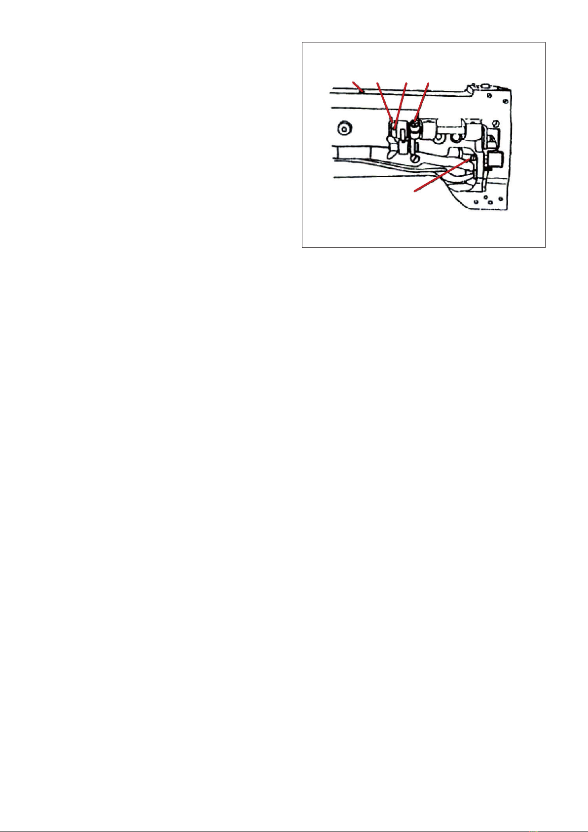
1 ) Turn the balance wheel to lift needle bar
1 to the upper end of its stroke. Place the
feed dog at this side in its travel turning the
balance wheel, and open the slide plate A.
(Fig 7)
2 ) Open on the drip pan, and then open the
hinged latch with left thumb and index finger. And pull bobbin case and bobbin from rotary
hook. While the latch is held open, the bobbin will be retained in the bobbin case. Release of
the latch and turning of the open side of the bobbin case downward will cause the bobbin to
drop out.
3 ) Hold the bobbin between the thumb and forefinger of your right hand and pull out a length
of about 5cm of thread. Holding the bobbin case in your left hand turn the open side up and
place the threaded bobbin into it. (Fig 7)
4 ) With the right hand guide the thread into the slot in the edge of the bobbin case. Then pull the
thread to the left, under tension spring 1 (Fig 7) and into the delivery eye. In order to keep the
bobbin from dropping out of the case when it is turned with the open side down, always keep
the hinged latch at the front of the bobbin case open.
5 ) Take the threaded bobbin case by the latch and place it on the center stud of the bobbin
case holder. Release latch and press bobbin case on to center stud until the latch catches the
undercut thereon with a click that can be heard. Permit about 5cm of bobbin thread to hand
down freely. Be sure to push the slide plate to the right before starting to sew.
8 THREADING (Fig 8)
1 ) Raise the needle bar to its highest point and
lead the thread from the thread stand the
following order. From the thread stand lead the
thread from back to front through the lower
guide hole in pin 1 on top of the machine arm,
then again from right to left through the upper
guide hole in this pin. Pass thread in weaving
fashion through the three holes in guide 2,
and from right to left over and between the
tension disc 3. Now pull thread downward and
from right to left beneath and around thread
controller 4, continue to pull thread upward
against the pressure of the wire spring into
the fork 5, in the thread controller. Guide upward through the point of controller discs 6, and
thread guide 7, and from right to left through the eye in take-up lever 8, down through thread
guide 7, again and then through 9, 10, 11 and from left to right through the eye of the needle 12.
2 ) After the above threading, hold the end of thread with your left hand, and turn the balance
wheel with your right hand so that bobbin thread may be picked up by needle thread. And put
their ends of thread back through under the presser foot for starting operation.
2
1
Fig 7
Fig 8
A
1
2
34
5
6
7
8
9
10
11 12