Highly Reliable SYSTEMS High-Rely Classic 5 Bay Mini-Tower User manual
Highly Reliable Systems
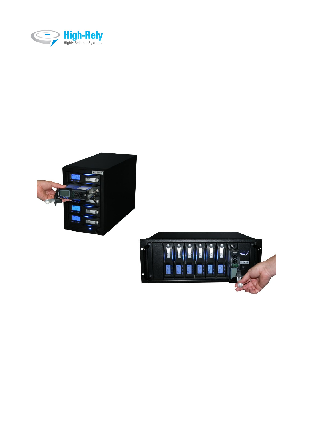
High-Rely Classic 5 Bay Mini-Tower and
5-10 Bay Rack Mount eSATA/ SB 3.0
Disk Based Backup Systems
Documentation V1.1
1 Copyright © 2011 by Highly Reliable Systems. All rights reserved.

READ THIS FIRST
Important Quick Start Information for your High-Rely drive
●YOUR MACH NE S SET TO OPERATE AT 115 VOLTS A/C. F THE OPERAT NG
VOLTAGE YOU NTEND TO USE T ON S H GHER SUCH AS 220/240 VOLTS A/C,
BE SURE TO MOVE THE VOLTAGE SELECTOR SW TCH ON THE BACK OF THE
UN T TO YOUR OPERAT NG VOLTAGE RANGE. FA LURE TO DO TH S COULD
RESULT N SER OUS DAMAGE TO YOUR UN T! Some units are “auto-switching”
which do not require this so there is no selector switch on the back of units with this feature.
●DO NOT ATTEMPT TO REMOVE High-Rely media from their drive bays without
“unlocking” the drive with the key first! Forced removal of the drive will void your
warranty. The key has a mechanical interlock that blocks the drive from being removed.
●High-Rely media will not “power up” until the key lock, on the front of the drive, is turned
to the locked and on position. This is by design and prevents accidental media removal.
●The latest Service Packs are important! Microsoft has continued to Debug removable drives
on the Windows 2000, XP, 2003, 2008, Vista, Win 7 product lines.
●Not all eSATA ports are created equal. For maximum compatibility, we recommend that
only controllers based on the Silicon mage chip sets be used. Other eSATA ports may only
recognize the first drive in a multi-drive system or may not function at all. Ports should
support Hot-Swap and “port multiplier” capabilities.
●f you are using multiple trays in the single bay of your High-Rely in PM/JBOD mode, you
may have a drive letter problem as you change your media. Windows will assign drive
letters randomly, which will cause your backup software to fail. ou can use the High-
Rely Drive Manager utility HRDM2.MSI to solve this problem. To do this, install
HRDM2 on the machine that the High-Rely system will be connected to. See
“Documentation SATAV2-2 ( the manual for the 1 Bay Slimline, 5 Bay, 7, 8 and 10 Bay
high-rely models)” available from our website, for more information.
●Particular photos in this manual may not be your exact unit.
The information in this manual primarily documents Windows 2000, 2003, 2008 or
X systems with some coverage of Vista. Although the High-Rely may work with
Windows NT, Linux, Mac OS X and other operating systems, at this time, our tech
support can assist with Windows platforms only.
2 Copyright © 2011 by Highly Reliable Systems. All rights reserved.

Table of Contents
1 ntroduction......................................................................................................................................4
2 Terminology......................................................................................................................................5
3 Front Panel controls and indicators..................................................................................................6
4 Back panel controls and indicators...................................................................................................7
5 nstallation - connecting to your computer.......................................................................................9
6 Operating Scenarios........................................................................................................................12
6.1 Mon-Fri/Sun (Auto Changer).................................................................................................12
6.2 Mon-Fri/Sun with full backups periodically...........................................................................12
6.3 Backing up Multiple Servers..................................................................................................12
7 Operation........................................................................................................................................14
7.1 Working with backup software..............................................................................................14
7.1.1 HRDM2.........................................................................................................................15
7.2 nserting/Removing Media....................................................................................................18
7.3 Reading/Setting Media Display.............................................................................................20
8 Troubleshooting..............................................................................................................................23
9 High-Rely product line, please visit our website at www.high-rely.com or see page 2 of HR
Documentation SATAV2-2 ( the manual for the 1 Bay Slimline, 5 Bay, 7, 8 and 10 Bay high-rely
models)...............................................................................................................................................24
10 Contact..........................................................................................................................................25
3 Copyright © 2011 by Highly Reliable Systems. All rights reserved.

1 Introduction.
As a successor to the long held territory of Tape backup systems, the economy and performance of
inexpensive hard drives as a backup medium can no longer be ignored. The High-Rely Classic 5
Bay Mini-Tower and 5-10 Bay Rackmount systems are the perfect tapeless solution for backup.
Their ability to hot-swap coupled with multiple drive capabilites allow for a functional replacement
of expensive robotic tape library systems. This is traditionally accomplished by assigning one bay
for each backup session in a repeating period. For example, Monday through Friday where each
day is designated a drive and thus an entire week's backup can occur without human intervention to
replace media.
The High-Rely Multi-bay Classic systems and helper software were designed to make configuring
your existing backup system software as easy as possible to start taking advantage of the speed,
reliability and cost saving of hard disk backup.
4 Copyright © 2011 by Highly Reliable Systems. All rights reserved.

2 Terminology.
The definition of some simple terms will help in understanding this manual:
•Hard Disk – The actual hard disk drive where data is stored.
•Tray – The removable cartridge which holds the hard disk.
•Media – The assembly of the hard disk in the tray.
•Receiver – Also referred to as the bay. The slot where the Media is inserted.
5 Copyright © 2011 by Highly Reliable Systems. All rights reserved.
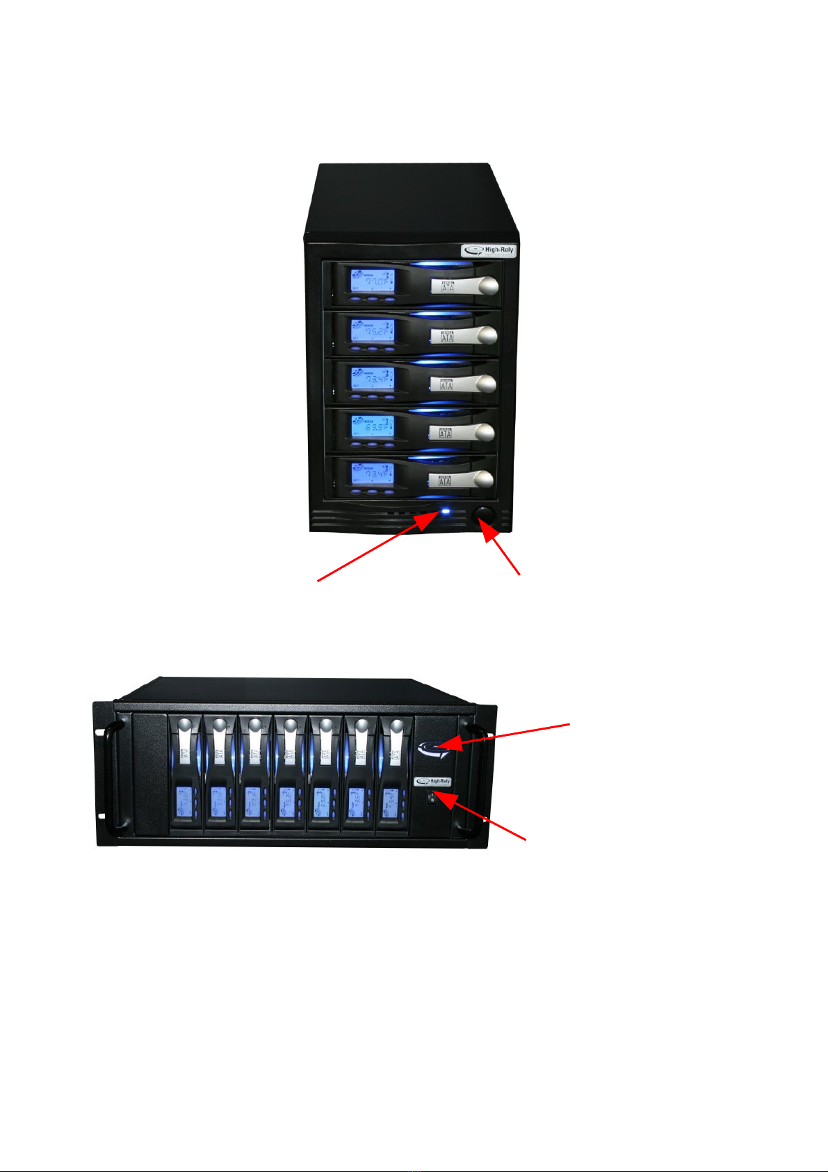
3 Front Panel controls and indicators
***Figure 1 – Front side of 5 Bay MT and 5-10 Bay RM.
6 Copyright © 2011 by Highly Reliable Systems. All rights reserved.
Power ndicator – Lit
when power is on.
Power switch – Push on/push
off type.
Power ndicator – Lit
when power is on.
*No front power
indicators on 10 bay.
Power switch – Rocker-Type.
*No front power switch on
10 Bay.

4 Back panel controls and indicators
***Figure 2 – Back side of 5 Bay MT.
7 Copyright © 2011 by Highly Reliable Systems. All rights reserved.
Auxiliary
Chassis Cooling
Fan
Power Supply
Cooling Fan
ESATA/USB 3.0
Back Panel
Power Supply
Voltage Selector
Standard
Business
Machine AC
Power Cord
Socket

***Figure 3 – Back side of 5-10 Bay RM.
8 Copyright © 2011 by Highly Reliable Systems. All rights reserved.
Auxiliary
Chassis Cooling
Fan
ESATA/USB 3.0
Back Panels
(only 1 if 5 bay
model)
Standard Business
Machine AC Power
Cord Socket
Power Supply
Voltage Selector
Power Supply
Main Power
Switch

Installation - connecting to your computer.
1. f using the Mini-Tower unit, be sure to locate the unit in an area where there is plenty of
ventilation. f using a Rack Mount (RM) unit, be aware that this unit is designed to mount
from the rack ears, no rack slide is provided or is necessary.
2. f you need to install a controller card in your host machine to connect your unit to, follow
the installation instructions for the controller card you're using. Not all USB 3.0 or eSATA
cards offer the same performance or comptilibilty. f you're intalling a controller in a PC -E
slot and can not see the device, under windows disk management (not explorer), then try
every available slot for the card.
3. NOTE: There are some slight operational differences if your unit is connected via USB
instead of eSATA. f your unit is connected via USB, it is advised to leave at least one
Media installed in the unit and running when swapping Media. This keeps the USB
connection to the host open. f at any point, all Media are powered down/removed such that
none remain on, it maybe necessary to power cycle the unit after Media is inserted in order
for the host to see the drives again. This is not an issue and this process is unnecessary if
your unit is connected via eSATA. Also, when connected via USB, whenever a Media is
inserted or removed, it is normal for the remaining devices to go offline momentarily then
return.
***Figure 4 – eSATA/USB 3.0 Back panel.
4. nstall your AC power cord to an 110VAC power source. F YOU'RE CONNECT NG TO A
220VAC POWER SOURCE, BE SURE TO CHANGE THE VOLTAGE SELECTOR ON
THE BACK OF YOUR UN T F RST!
5. Turn power on unit on.
6. nstall media and turn the keylock to the locked/on position (see section, nserting and
removing media).
7. Connect your patch cable (USB or eSATA) from the eSATA or USB 3.0/2.0 port of your
9 Copyright © 2011 by Highly Reliable Systems. All rights reserved.
USB 3.0
(SuperSpeed) to
host connection
ESATA to host
connection
RA D Mode
Setting Switches
Change RA D Mode
to Selection (use open
paper clip, hold for
20 seconds while
powering unit on)

host computer to the proper connector on the back of your unit. Note: f you have more than
5 bays in your unit (which the 5-10 bay RM unit permits), you will have two of these panels
on your unit. n the RM unit, if 5 bays, there is one panel which controls the 5 bays. f 7
Bays, one panel controls 4, the other controls 3. f 8 bays, each panel controls 4 bays. f 10
bays, each panel controls 5 bays. Each panel must be connected to the host or all the bays
will not show up. n Figure XXX above you will see the USB 3.0/2.0 'B' type connector and
the eSATA connector. Only one maybe plugged in at a time. f you switch from USB to
eSATA or vice-versa, you must wait at least 10 seconds after removing one cable before
plugging in the other. f after switching cables, no devices appear, try power cycling the
unit. f that fails, look back to the host controller for issues.
8. Look for new volumes to appear using Windows Drive Management. f the drive is not
formatted, it will not appear to explorer but will still show in Drive Management and will
need to be formatted. f you do not see the drive appear, try reseating your cables. Try
power cycling both the host and the High-Rely unit. Again, if this fails, consider controller
issues and compatibility.
10 Copyright © 2011 by Highly Reliable Systems. All rights reserved.

ADVANCED USERS
Your unit has the ability to perform various RAID operations. While the hardware will perform
these functions, they are not advised in these models by High-Rely and High-Rely Technical support
will not be able to assist you with these configurations. Nonetheless, if you chose to use them, we
recommend you test the operation thoroughly. Use these features at your own RISK!
WARNING! Changing the RAID Mode can cause all data to be lost!!! Pick and set the RAID
Mode prior to formatting and using the volume(s).
*=Default settings
Mute (Speaker) Off – Audible Alarm during degraded or
failed conditions.
On* – Audible alarm is muted.
EZ On – Auto rebuild to spare drive. Off* – Rebuild to fresh drive when
inserted.
RAID Type Description M2 M1 M0
JBOD ndividual Volumes. Off* Off* Off*
RA D 0 All installed volumes are Striped. On On On
RA D 1 or 10 Mirror. Mirror's installed drives. (2 drives for mirror, 4
drives for RA D 10)
On On Off
RA D 3 RA D 3 functionality. On Off Off
RA D 5 RA D 5 functionality for installed drives. Hot spares
are those installed after RA D 5 is created.
Off On Off
B G Concatenates all drives. On Off On
CLONE Clones drives (all drives get the same data). Off On On
***Figure 5 “Back Panel of Model B, Dip Switch Settings”
11 Copyright © 2011 by Highly Reliable Systems. All rights reserved.

6 Operating Scenarios.
6.1 Mon-Fri/Sun (Auto Changer)
n this scenario, the High-Rely unit is connected directly to a Windows server which is running
backup software on a daily basis. The user has multiples of their weekly backup sets in media. For
example, if they have a 5 bay to use for Monday through Friday, then they have (5 X) five times
however many weeks they wish to go back. f they are backing up Monday through Sunday then
they have (7X) 7 times. n this example we shall say the user has a 5 bay and has three weeks back
of media so he has 15 pieces of media.
Each of 5 pieces of media is given a different volume letter but those letters repeat for each set.
For example, there are three drives with the volume letter H:, three with :, three with J:, three with
K: and three with L:. The Hs are all Mondays, the s are all Tuesdays, the Js are all Wednesdays
and so forth. Thus, one weeks worth of media consists of 5 drives letters, H through L.
His backup software is programmed so that each night at 11:00pm it does a full backup. And on
Mondays, it does a full backup to H drives, Tuesdays are drives, Wednesdays are J drives, and so
forth. Every Monday morning, he pulls the entire week's worth of drives and installs another
week's set.
Additionally, because windows does not like to assign different volumes the same drive letter and
will confuse them, he has installed High-Rely's free utility, HRDM2, to make sure windows assigns
the proper drive letter to each drive.
Hence, this type of installation only requires that the media is touched once a week. f the user had
a 10 bay device, the media would only need to be touched once every two weeks.
6.2 Mon-Fri/Sun with full backups periodically.
n this scenario, the user is using backup software with a "incremental" feature which allows it to
backup only data that has changed in multiple sets. For this example, the user has a 5 bay unit and
has 15 pieces of media. The user is doing a complete backup every week and incrementals during
the week. He has the software set up to place the incrementals on the same drive as the full backup.
Thus he need only change the media once a month and has 3 months worth of storage. His full
backup is approximately 400GB and his daily incrementals are about 10GB so he can easily fit an
entire week on a single 1TB drive. As in the first example above, the user is using HRDM2 to
make sure that drive lettering is not confused.
6.3 Backing up Multiple Servers
n this example, the user has a 5 bay unit and is backing up 5 servers to the unit. Like the example
above, he is using backup software with an incremental feature. The server the High-Rely is
attached to is sharing one of the 5 drives with each of the servers. Thus, share H goes to server 1,
share goes to server 2, share J goes to server 3 and so forth. The backup software is loaded onto
each of the servers and is set to do a full backup once a week and incrementals for the rest of the
week. Again, HRDM2 is used as in the examples above to keep windows from confusing drive
letters. Also, the feature in HRDM2 to reactivate shares once a drive has changed is also enable.
Without this feature, each drive would have to be re-shared after it was changed.
The set of 5 media is changed once a week before the day of the full backups. Also, the backup
start time of each server are set to start well after the backup of the previous server has ended so that
12 Copyright © 2011 by Highly Reliable Systems. All rights reserved.

multiple servers are not trying to backup at the same time, otherwise, the network connection to the
machine the High-Rely is on can become swamped and the jobs may not complete or connection
problems could occur.
13 Copyright © 2011 by Highly Reliable Systems. All rights reserved.

7 Operation.
7.1 Working with backup software
The high-rely multibay devices are, in their simplest configuration, a set of external hard drives.
Any software which will work with external hard drives should work with the high-rely equipment.
But, there is a technical issue to consider depending on how you connect the devices.
f you connect them to your host via eSATA, everything works as you would expect – when you
install a media, a drive shows up on the host and dissappears when you remove it. But, on USB,
whenever a media is inserted or removed, all drives go off line and then return. Thus, if your
software is configured to use more than one drive at a time and that drive must stay attached, there
maybe issues when you swap media.
Also, if your software needs to use the multple drives witht he same drive letter, then you need to
read the section below on HRDM2.
14 Copyright © 2011 by Highly Reliable Systems. All rights reserved.
7.1.1 HRDM2
HRDM2 is free software from High-Rely which allows you configure multiple drives with the same
drive letter assignment. For example, if you have 3 weeks worth of media, then you may have 3
drive H's for Monday, three drive 's for tuesday and so forth. However, windows does not
gauarantee it will always assign the same letter for mutlpile drives which can make configuring
your backup software for such very frustrating or impossible. This section does not completely
cover the details of working with HRDM2 which are in the help files in the application. However,
it does cover basic installation.
nstallation
1. Run setup.exe from your installation disk or downloaded zip file.
2. Follow the installation wizard prompts.
Setup
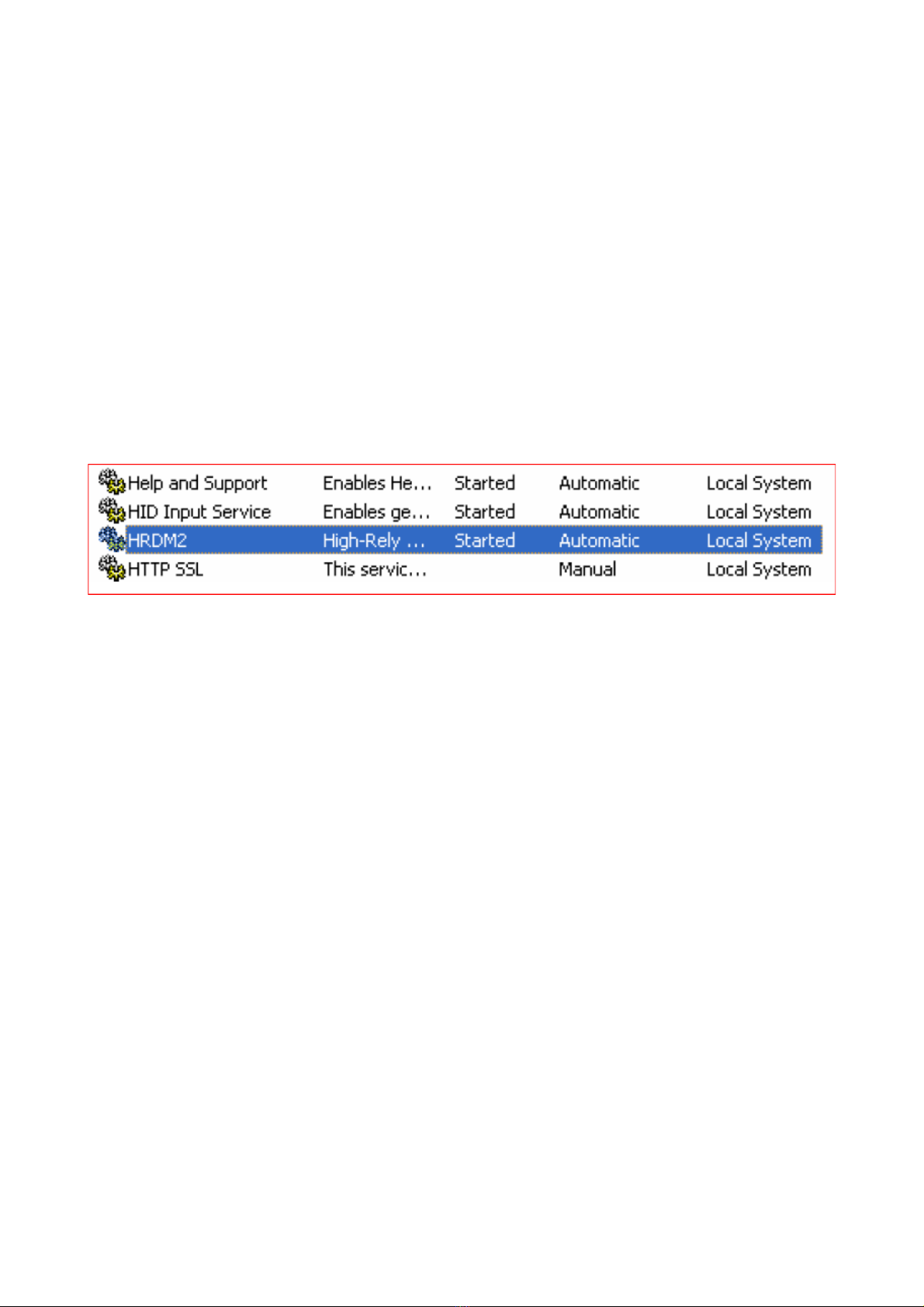
1. The drive manager service is configured to start automatically at boot time. t will appear in
your services window as shown:
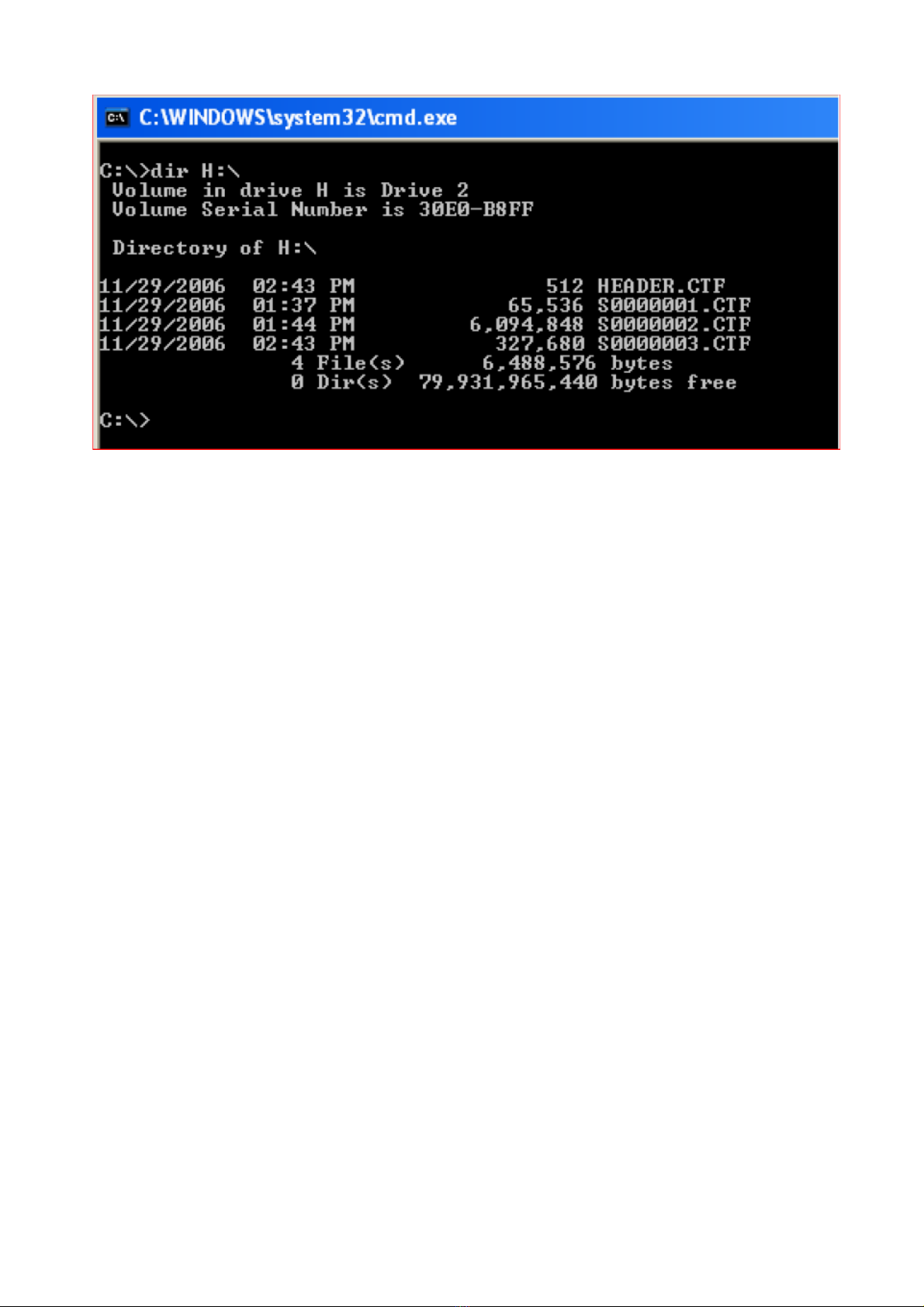
2. To assign letters to drives you must first acquire each drive’s Volume Serial Number. One way
to get this information is to open a Command Prompt, and use the ‘dir’ command, as show here:
15 Copyright © 2011 by Highly Reliable Systems. All rights reserved.
3. Once you have all of your Volume Serial Numbers, open the file called HRDM. N , which is
located in the same folder that you installed the program in using the nstall Wizard.
(Default location is: C:\Program Files\Highly Reliable Systems\HRDM2\HRDM2.ini)
16 Copyright © 2011 by Highly Reliable Systems. All rights reserved.
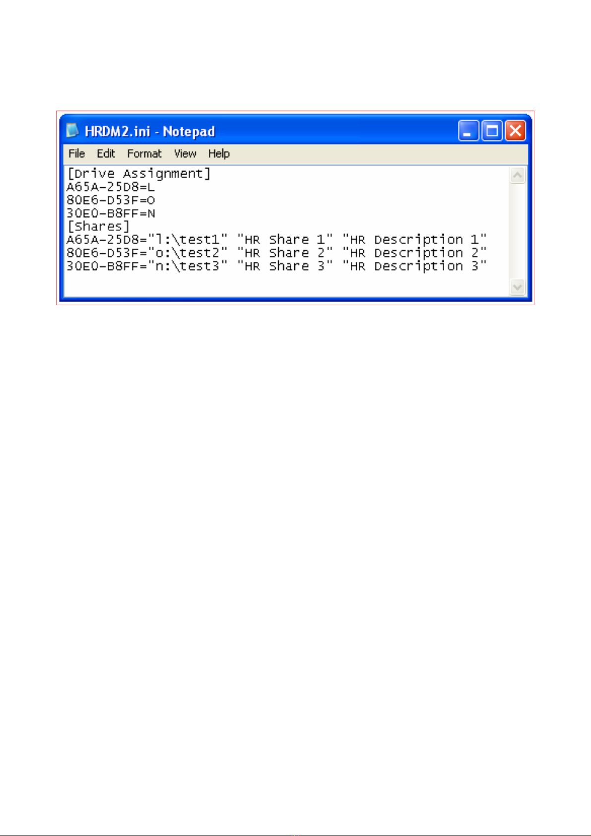
4. Enter each Volume Serial Number, then an equal sign, then the letter you want under the line
‘[Drive Assignment]’. Follow the same format under the line ‘[Shares]’ but provide the share
directory, share name and description within quotes. Enter one such entry per line as shown
here:
5. Save the file.
6. Any changes made to the HRDM2.ini file require newly configured media to be restarted before
changes will take effect. This means if a drive’s Volume Serial Number is added to the
HRDM2.ini file after the drive is turned to the on position then it needs to be restarted before the
new assignments will take effect.
17 Copyright © 2011 by Highly Reliable Systems. All rights reserved.
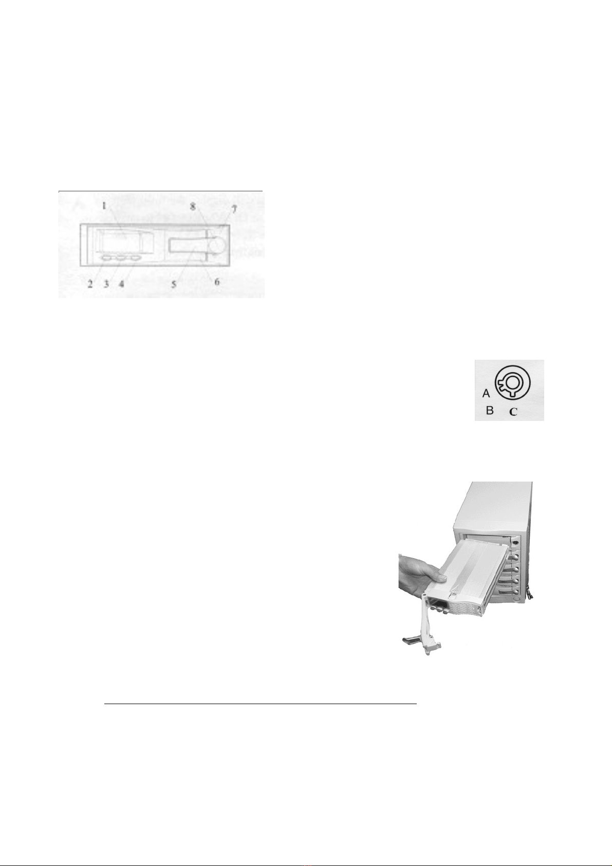
7.2 Inserting/Removing Media.
The following diagram identifies the front of the HR removable drive and gives the names of each
item. To remove the media properly you will need to understand the function of the release levers
and the key lock mechanism (items 5, 6, and 8).
1. LCD Display
2. Set Button
3. Up button
4. Down button
5. Lock cover lever (Small lever)
6. Release Lever (Large lever)
7. Front Bezel of HR Receiver Frame
8. Hidden Key Lock
The High-Rely backup system makes use of SATA hard drives.
Many SATA drives are specifically designed to support hot
swap. The High-Rely trays make it possible to also hot swap (or
warm swap) SATA drives because before a drive is removed it is
powered down safely by turning the key lock on the front of the
unit. This technique allows even SATA drives drives to be
removed and installed while computer power is on (Hot swapped).
To insert the media, first make sure the lock is in the unlocked
position (position C). Proper orientation of the removable drive is with the blue buttons to the left as
shown in the photo. Notice that the entire large lever, called the “release lever” is in the fully open
position. Do not attempt to insert the drive with the release lever closed.
Push the drive all the way in until you feel resistance. At this time move the small lever (the “lock
cover” lever) to its midway (position E).
18 Copyright © 2011 by Highly Reliable Systems. All rights reserved.

Move the larger “release lever” towards the closed position, using the lever action of the mechanism
to pull the drive in the last few centimeters. Close the release lever until it snaps. f it will not snap
shut check to ensure that you have the smaller lock cover lever in the partially closed position E.
Now insert the key and turn it clockwise to the “A” position to power up the drive as shown in the
photo. The B position of the lock is considered “off” and is not used in the High-Rely system.
At this point, if master power to the unit is on, you should see the LCD front panel of the drive light
up and possibly hear the hard drive spin up. f you do not, the drive is not seated properly. Remove
it and try re-seating it. Once you have successfully powered up the drive you should flip the lock
cover to the fully closed or D position.
Once the drives spin up, Windows should recognize the new drive and will dynamically assign a
drive letter to your new media. Removing the media is the exact same process but in reverse.
However, be sure the media is not being written to by the host before removing it or the data on the
drive could be incomplete or corrupted.
19 Copyright © 2011 by Highly Reliable Systems. All rights reserved.
In the final step the “Lock
Cover” should be moved to
position D
Lock Cover lever position E
is used to insure the larger
“release lever” will snap
shut

7.3 Reading/Setting Media Display
LCD Display on Media tray
1. Hard Drive activity symbol (simulates spinning disk when drive is in use)
2. Master/Slave Status display (Unused feature of the LCD display. Always displays as
slave)
3. Alert Symbol (Symbol is on when the unit is in alarm status)
4. Fan Status Display (Simulates a rotating fan to show that drive fan is spinning)
5. Thermometer Symbol (On when numeric display is showing temperature)
6. Digit display (Displays temperature normally)
7. Down arrow (positioned above down button)
8. Hour ndicator (On when numeric display is showing days/hours of operation)
9. Degrees Symbol (On when numeric display is showing temperature)
10. Decimal Point
11. Up arrow (positioned above up button)
12. Day ndicator (On when numeric display is showing days/hours of operation)
13. SET indicator (positioned above SET button)
14. Hard Drive Usage Time Symbol (On when display is showing days/hours of operation)
20 Copyright © 2011 by Highly Reliable Systems. All rights reserved.
This manual suits for next models
2
Table of contents
Other Highly Reliable SYSTEMS UPS manuals


