manuals.online logo
Brands
  1. Home
  2. •
  3. Brands
  4. •
  5. HP
  6. •
  7. UPS
  8. •
  9. HP R1500 Assembly instructions

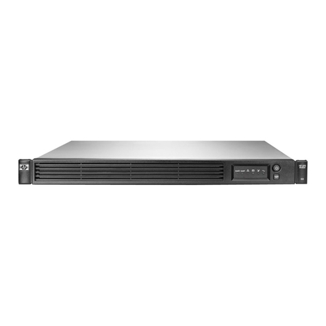
HP R1500 Assembly instructions

Product End-of-Life Disassembly Instructions
Product Category: Other Products
Marketing Name / Model
[List multiple models if applicable.]
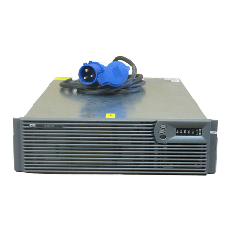
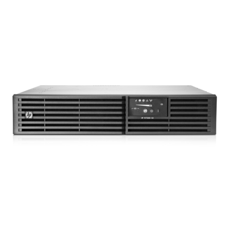
HP R1500 G4 NA UPS
HP R1500 G4 JP/TWN UPS
Purpose: The document is intended for use by end-of-life recyclers or treatment facilities. It provides the basic instructions
for the disassembly of HP products to remove components and materials requiring selective treatment, as defined by EU
directive 2002/96/EC, Waste Electrical and Electronic Equipment (WEEE).
1.0 Items Requiring Selective Treatment
1.1 Items listed below are classified as requiring selective treatment.
1.2 Enter the quantity of items contained within the product which require selective treatment in the right column, as
applicable.
Item Description Notes
Quantity
of items
included
in product
Printed Circuit Boards (PCB) or Printed Circuit
Assemblies (PCA)
With a surface greater than 10 sq cm
2
Batteries
All types including standard alkaline and lithium coin
or button style batteries Lead-acid battery
3
Mercury-containing components
For example, mercury in lamps, display backlights,
scanner lamps, switches, batteries
0
Liquid Crystal Displays (LCD) with a surface greater
than 100 sq cm
Includes background illuminated displays with gas
discharge lamps
0
Cathode Ray Tubes (CRT)
0
Capacitors / condensers (Containing PCB/PCT)
0
Electrolytic Capacitors / Condensers measuring
greater than 2.5 cm in diameter or height
Electrolytic Capacitors
3
External electrical cables and cords
2
Gas Discharge Lamps
0
Plastics containing Brominated Flame Retardants
weighing > 25 grams (not including PCBs or PCAs
already listed as a separate item above)
0
Components and parts containing toner and ink,
including liquids, semi-liquids (gel/paste) and toner
Include the cartridges, print heads, tubes, vent
chambers, and service stations.
0
Components and waste containing asbestos
0
Components, parts and materials containing
refractory ceramic fibers
0
EL-MF877-00 Page 1
Template Revision B
PSG instructions for this template are available at EL-MF877-01
Components, parts and materials containing
radioactive substances
0
2.0 Tools Required
List the type and size of the tools that would typically be used to disassemble the product to a point where components
and materials requiring selective treatment can be removed.
Tool Description
Tool Size (if
applicable)
Star Head Screw Driver
M3
Cross Head Screw Driver
M3,M4
Plastic Nipper
Normal
Nut Driver
M4
Electric Iron
Normal
3.0 Product Disassembly Process
3.1 List the basic steps that should typically be followed to remove components and materials requiring selective treatment:
1. Remove the middle bezel and left panel
2. Disconnect the battery connector, and press on/off button to discharge the rest electricity.
3. Loosen the screws fixing the battery door, remove the battery door, and pull out the battery.
4. Loosen the screws fixing the right panel ASSY, and remove the right panel ASSY.
5. Disconnect the LCD cable and PCBA.
6. Loosen the screws fixing the top cover, and remove the top cover.
7. Disconnect the cables connecting to Slot box, AVR, rear FAN, COM PCBA, and rear panel ASSY, and disassemble
the cable clips sticking on the mainframe, and loosen the screws fixing the main PCBA, then remove the main PCBA .
8. Cut off the cable tie, disconnect the cable connecting to COM PCBA, loosen the nuts fixing the AVR, and then remove
the AVR.
9. Lossen the screws fixing rear panel ASSY and then remove the rear panel ASSY.
10. Remove the RPO connector, loosen the screws fixing SLOT box, COM PCBA and rear FAN, loosen the nut fixing
ground cable and then remove the Slot Box, COM PCBA and rear FAN, outlet.
3.2 Optional Graphic. If the disassembly process is complex, insert a graphic illustration below to identify the items
contained in the product that require selective treatment (with descriptions and arrows identifying locations).
EL-MF877-00 Page 2
Template Revision B
PSG instructions for this template are available at EL-MF877-01
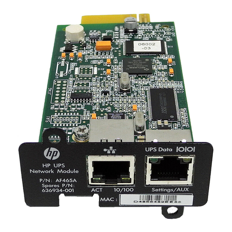
2. Disconnect the battery connector, and press on/off button to discharge the rest electricity.
1. Remove the middle bezel and left panel.
EL-MF877-00 Page 3
Template Revision B
PSG instructions for this template are available at EL-MF877-01
3. Loosen the screws fixing the battery door, remove the battery door, and pull out the battery.
Press on/off button to discharge rest electricity
M3 Cross
driver
EL-MF877-00 Page 4
Template Revision B
PSG instructions for this template are available at EL-MF877-01
4. Loosen the screws fixing the right panel ASSY, and remove the right panel ASSY.
M3 star
driver
EL-MF877-00 Page 5
Template Revision B
PSG instructions for this template are available at EL-MF877-01
5. Disconnect the LCD cable and PCBA.
M3 cross
driver
EL-MF877-00 Page 6
Template Revision B
PSG instructions for this template are available at EL-MF877-01
6. Loosen the screws fixing the top cover, and remove the top cover.
M3 Star
driver
EL-MF877-00 Page 7
Template Revision B
PSG instructions for this template are available at EL-MF877-01
7. Disconnect the cables connecting to Slot box, AVR, rear FAN, COM PCBA, and rear panel ASSY, and disassemble
the cable clips sticking on the mainframe, and loosen the screws fixing the main PCBA, then remove the main PCBA .
Disconnect all terminal
M4 Cross Screw driver
EL-MF877-00 Page 8
Template Revision B
PSG instructions for this template are available at EL-MF877-01
M3 Cross driver
EL-MF877-00 Page 9
Template Revision B
PSG instructions for this template are available at EL-MF877-01
8. Cut off the cable tie, disconnect the cable connecting to COM PCBA, loosen the nuts fixing the AVR, and then
remove the AVR.
9. Loosen the screws fixing rear panel ASSY, and then remove the rear panel ASSY.
Nut driver
Cut off the cable tie
EL-MF877-00 Page 10
Template Revision B
PSG instructions for this template are available at EL-MF877-01
10. Remove the RPO connector, loosen the screws fixing Slot box, COM PCBA, and rear FAN, loosen the nut fixing
ground cable and then remove the Slot box, COM PCBA, and rear FAN, outlet.
M3 Star driver
M4 Cross driver
M3 Star driver
Press these clip and push out
EL-MF877-00 Page 11
Template Revision B
PSG instructions for this template are available at EL-MF877-01
Nut driver
M3 Cross driver
EL-MF877-00 Page 12
Template Revision B
PSG instructions for this template are available at EL-MF877-01

Other manuals for R1500

10

Other HP UPS manuals

HP R1500 User manual

HP

HP R1500 User manual

HP R7000 INTL User manual

HP

HP R7000 INTL User manual

HP Pavilion G4T-1000 Installation instructions

HP

HP Pavilion G4T-1000 Installation instructions

HP Presario R3000 - Notebook PC User manual

HP

HP Presario R3000 - Notebook PC User manual

HP R1500 User manual

HP

HP R1500 User manual

HP HP StoreOnce G3 Operator's manual

HP

HP HP StoreOnce G3 Operator's manual

HP R1500 User manual

HP

HP R1500 User manual

HP R5000 User manual

HP

HP R5000 User manual

HP T750 G4 NA/JP User manual

HP

HP T750 G4 NA/JP User manual

HP Enterprise R1500 G4 UPS Assembly instructions

HP

HP Enterprise R1500 G4 UPS Assembly instructions

HP T1000 XR User manual

HP

HP T1000 XR User manual

HP UPS R5500 User manual

HP

HP UPS R5500 User manual

HP R12000 XR User manual

HP

HP R12000 XR User manual

HP R7000 INTL User manual

HP

HP R7000 INTL User manual

HP Pavilion t500 - Desktop PC User manual

HP

HP Pavilion t500 - Desktop PC User manual

HP R1500 User manual

HP

HP R1500 User manual

HP StoreEver 1U User manual

HP

HP StoreEver 1U User manual

HP J4367A - UPS R3000 XR User manual

HP

HP J4367A - UPS R3000 XR User manual

HP Enterprise R1500 G4 UPS User manual

HP

HP Enterprise R1500 G4 UPS User manual

HP HPE T750 G4 User manual

HP

HP HPE T750 G4 User manual

HP RDX USB 3.0 User manual

HP

HP RDX USB 3.0 User manual

HP R/T2200 User manual

HP

HP R/T2200 User manual

HP R2200 ERM User manual

HP

HP R2200 ERM User manual

HP R1500 G2 User instructions

HP

HP R1500 G2 User instructions

Popular UPS manuals by other brands

Eaton Powerware 9395 User and installation guide

Eaton

Eaton Powerware 9395 User and installation guide

CyberPower LX1100G-FC user manual

CyberPower

CyberPower LX1100G-FC user manual

Symantec NetBackup 5330 Hardware installation guide

Symantec

Symantec NetBackup 5330 Hardware installation guide

Wave RT9 Powershelf Installation & operation manual

Wave

Wave RT9 Powershelf Installation & operation manual

Eaton 9PX6KIRTN-L user guide

Eaton

Eaton 9PX6KIRTN-L user guide

Njoy Garun 30KL user manual

Njoy

Njoy Garun 30KL user manual

Atlantis LinePower 1151 manual

Atlantis

Atlantis LinePower 1151 manual

JALpower JP5530 Series user manual

JALpower

JALpower JP5530 Series user manual

GE GT6000 user manual

GE

GE GT6000 user manual

Eaton EX EXB 1000 installation manual

Eaton

Eaton EX EXB 1000 installation manual

CyberPower Paragon OL1000RMXL2U user manual

CyberPower

CyberPower Paragon OL1000RMXL2U user manual

Integra Xmart SUPRA 500 user manual

Integra

Integra Xmart SUPRA 500 user manual

INFOSEC M4T user manual

INFOSEC

INFOSEC M4T user manual

CyberPower CP750LCD user manual

CyberPower

CyberPower CP750LCD user manual

Legacy Legend SB500R user manual

Legacy

Legacy Legend SB500R user manual

Forza FDC-106K user manual

Forza

Forza FDC-106K user manual

ONEAC ON Series User instruction manual

ONEAC

ONEAC ON Series User instruction manual

Belkin F6H350-SER user manual

Belkin

Belkin F6H350-SER user manual

manuals.online logo
manuals.online logoBrands
  • About & Mission
  • Contact us
  • Privacy Policy
  • Terms and Conditions

Copyright 2025 Manuals.Online. All Rights Reserved.