manuals.online logo
Brands
  1. Home
  2. •
  3. Brands
  4. •
  5. HIK VISION
  6. •
  7. DVR
  8. •
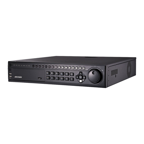
  9. HIK VISION DS-7608NI-E2/8P User manual

HIK VISION DS-7608NI-E2/8P User manual

NVR Quick Start Guide (QSG): DS-7604NI-E1/4P, DS-7608NI-E2/8P,
DS-7616NI-E2/16P, v3.4.3


 W H A T ’ S I N T H E B O X
Make sure the fo owing items are in your box:
NVR Mouse Remote 7604: Power Supp y HDD Screws
7608/7616: AC Cord
HDD HDD Cab es Ear Mounts QSG DVD-ROM
(7608/7616 on y)



M E N U T R E E
Use this menu tree to navigate the embedded menus.


 R O N T P A N E L
Figure 1, DS-76xxNI-Ex/xP Front Pane
1. Indicators
• Power: Green when system is running
• Status: B inks red when data is being read from or written to HDD
• Tx/Rx: B inks green when network connection is functioning proper y
2. USB Port Connects USB mouse or USB f ash memory devices


 R E A R P A N E L S
Figure 2, DS-7604NI-E1/4P Rear Pane
Figure 3, DS-7608NI-E2/8P Rear Pane
Figure 4, DS-7616NI-E2/16P
No.
Item
Description
1
Audio In
RCA
connector
2
Audio Out
RCA
connector
3
VGA
Out
DB
-
15 connector for VGA output
to d
isp ay oca video output and
menu
4
HDMI Out
HDMI video output
connector
5
A arm I/O
A
arm
input
/
output
connectors
6
LAN Interface
Connector for LAN (Loca Area Network)
7
USB
USB
port for additiona
devices
8
Grounding Screw
Ground (needs to be connected when NVR starts up)
9
Power Input
48 VDC power supp y (DS
-
7604
NI
-
E1/4P
)/
100 to 240 VAC
(DS
-
7608NI
-
E2/8P, DS
-
7616NI
-
E2/16P)
10
Power Switch
Switch for turning on/off the
device
11
Network Interfaces w/PoE
IP camera input
s
and PoE output
s
1 C O N N E C T D E V I C E S
1. Connect power supp y p ug (DS-7604NI-E1/4P) or AC cord (DS-7608NI-E2/8P) to the NVR.
2. Connect NVR to LAN using Cat 5e cab e.
3. Connect video monitor(s) to NVR using HDMI and/or VGA cab es, as appropriate.
4. Connect mouse to USB port (wire ess mouse can be used in ieu of inc uded mouse).
5. Connect to audio I/O using RCA connectors.
2 S T A R T T H E N V R
1. P ug power cord into 110 VAC out et (surge suppressor is recommended).
2. Turn power switch on. Power indicator LED wi turn green to indicate unit is starting.
3. After startup, power indicator LED wi remain green.
3 L O C A L A C T I V A T I O N
System access requires a secure, user-assigned password.

Set
Admin Password
1. First-time access requires user to create an
admin password.
2. Input the same password in the Create New
Password and Confirm New Password
text fie ds.
Strong Password REQUIRED
Password must contain 8 to 16 characters,
combining numbers, ower and upper case
etters, and specia characters. At east two
types of the above-mentioned characters
are required. A so, reset password
regu ar y.
3. C ick OK to save password and activate
device.
3
L O C A L A C T I V A T I O N ( c o n t i n u e d )
Password Strength Levels
STRENGTH
LEVEL
DESCRIPTION
Leve 0 (Risky)
DVRs
will not
accept password
Password is fewer than
8
characters, contains on y
1
type of
character, is the same as the user name, or is the mirror writing of the
user
name.
Leve 1
(Weak)
DVRs
will
accept
password
Password c
ontains
number + owercase ett
er or number + uppercase
etter
and is
at
east
8
characters.
Leve 2
(Medium/Fair)
DVRs
will
accept
password
Password contains
2
types of characters
(
neither
number + owercase
etter
nor
number + uppercase
etter)
and is
at
east
8
characters.
Leve 3
(Strong)
DVRs
will
accept
password
Password contains more
than three types of characters
and is
at
east
8
characters.
NOTE 1: The strength eve indicator co ors can vary by activation process, mode
number, and device type. Typica : Risky (no co or), Weak (pink), Fair
(ye ow), Strong (green).
NOTE 2: PASSWORD CHARACTERS ALLOWED (ASCII On y):
• Lowercase ASCII Letters
a b c d e f g h I j k m n o p q r s t u v w x y z
• Uppercase ASCII Letters
A B C D E F G H I J K L M N O P Q R S T U V W X Y Z
• Numera s
0 1 2 3 4 5 6 7 8 9
• Specia Characters
. - _ : / @ , ? ! ‘ ( ) $ & “ [ ] { } # % ^ * + = \ | < >

Set Unlock Pattern
Admin user wi be prompted to configure an
un ock pattern for ogin in p ace of a password.
1. Ho d down eft mouse button and draw a
pattern by connecting at east four dots on
the screen, with each dot connected on y
once). Re ease mouse button when done.
2. Draw the same pattern again to confirm it.
NOTE: If you forget your pattern, c ick on
“Forgot Password” to disp ay the
norma admin ogin dia og box.
 Log In (Unlock Pattern)
1. Draw the un ock pattern to un ock system.
3
L O C A L A C T I V A T I O N ( c o n t i n u e d )

Log In
(Dialog Box)
1. User Name fie d wi be prefi ed with
“admin.”
2. Input Password (account ocks for 30
minutes after 7 incorrect attempts).
3. C ick OK.
4 I N I T I A L I Z E T H E H A R D D R I V E ( I N E E D E D )
The system is set up to record upon power up and wi beep if the hard drives are not initia ized.
1. Go to MENU > SYSTEM CONFIGURATION > HDD.
2. Use the checkboxes to se ect the HDDs that need to be initia ized.
3. Press INIT.
NOTE: Factory insta ed HDDs come initia ized. Initia izing again wi erase any
record video (this does not affect settings).
q
qq
q
HDD LIST
w
ww
w TOTAL HDD SPACE
e
ee
e REE SPACE
q
w
e
5 S E T D A T E A N D T I M E
1. Go to MENU > SYSTEM CONFIGURATION > GENERAL.
6 S E T U P N E T W O R K A C C E S S
1. Set up access to cameras remote y: MENU > SYSTEM CONFIGURATION > NETWORK.
2. Enab e DHCP (check the checkbox).
3. Press Refresh button to update the IPv4 address, subnet mask, and IPv4 defau t gateway.
4. Disab e DHCP (uncheck the checkbox).
5. Change “Preferred DNS Server” va ue to 8.8.8.8 ( eave A ternate DNS Server b ank).
q
DATE/TIME
Date and time settings
w TIME ZONE
Time zone and day ight savings
time settings
e ENABLE NTP
Network Time Protoco settings
q
q q
q
GENERAL TAB
Se ect this tab
w
ww
w
NIC TYPE
Set LAN type
e
e e
e
ENABLE DHCP
Check box so that router wi
assign IP address
r
r r
r
RE RESH
Press to update va ues
t
t t
t
IP V4 ADDRESS
Defau t 192.0.0.64
y
y y
y
PRE ERRED DNS SERVER
Defau t is 8.8.8.8
u
u u
u
ALTERNATE DNS SERVER
Leave b ank
q
w
e
q
w
e
r
t
y
u
7 S E T C A M E R A P O R T S
After assigning the IP information, c ick the More Settings tab.
The More Settings tab contains the ports that need to be forwarded for remote access.
• SERVER PORT is responsib e for the mobi e app and c ient software og-in.
• HTTP PORT is responsib e for Web browser og-in.
• RTSP PORT is responsib e for video/audio streaming.
NOTE: The HTTP port, server port, and RTSP can be changed, if desired, to
avoid conf icts with the ISP or if mu tip e devices are insta ed at a sing e
ocation.
8 S E T U P P O R T O R W A R D I N G
Port forwarding redirects communication from one address/port number to another to make services on a
protected network avai ab e to hosts on an externa network.
1. Log into the router, and proceed with port forwarding. Port forwarding steps differ by router. For
port forwarding assistance, contact your Internet Service Provider (ISP) or router manufacturer. A so
refer to www.portforward.com for step-by-step instructions.
NOTE: Hikvision USA is not associated with www.portforward.com and is not
responsib e for any activity between the user and www.portforward.com.
P ease avoid accidenta y down oading any software from www.portforward.com.
2. Proceed to the Routers section on the website for step-by-step instructions.
9 S E T U P D D N S ( D y n a m i c D o m a i n N a m e S y s t e m )
DDNS a ows users with dynamic (changing) IP address to remote y access their unit.
1. C ick on the DDNS tab.
2. Check the DDNS checkbox.
3. DDNS Type: HiDDNS (defau t)
4. Continent/Country: Auto Detection (defau t)
5. Server Address: www.hik-on ine.com (U.S. defau t)
6. Create a Device Domain Name (cannot begin with a number, contain spaces, specia characters, or
upper case etters).
7. Create a User Name.
8. Password: System uses device seria number; cannot be changed.
9. After the changes have been made, press Apply to disp ay the Succeeded message. (If the Domain
Name does not meet acceptab e criteria, or is a ready registered, an error message wi appear.)
10 A D D I P C A M E R A S
1. Right c ick a window in Live View mode to disp ay the menu.
2. C ick Menu to disp ay Menu choices.
3. C ick Cameras Setup to disp ay the Add Cameras window.
4. Add camera(s) as fo ows:
• Hikvision Camera Connected to Unit’s PoE Port — Wi automatica y be added to an NVR
camera channe (D
x
) and wi be visib e on the camera ist in white within two minutes.
• Hikvision Camera Connected to the Network but Not Unit’s PoE Ports — Wi automatica y be
detected and disp ayed at bottom of the camera ist in ye ow. Must be added to an NVR camera
channe manua y:
1) C ick an unused camera channe ’s D
x
checkbox.
2) C ick the EDIT (Penci ) button to disp ay the Edit IP Camera window.
3) Use pu -down menu to change Adding Method from “P ug and P ay” to “Manua .”
4) Enter the camera’s IP address and other information as required.
5) Press the OK button to add the camera.
1 0
A D D I P C A M E R A S ( c o n t i n u e d )
•
••
• Hikvision Cameras Not Detected — Must be added manua y:
1) C ick an unused camera channe ’s D
x
checkbox.
2) C ick the EDIT (Penci ) button to disp ay the Edit IP Camera window.
3) Use pu -down menu to change Adding Method from “P ug and P ay” to “Manua .”
4) Enter the camera’s IP address and other information as required.
5) Press the OK button to add the camera.
•
••
• Third-Party Cameras — Must be added manua y:
1) C ick an unused camera channe ’s D
x
checkbox.
2) C ick the EDIT (Penci ) button to disp ay the Edit IP Camera window.
3) Use pu -down menu to change Adding Method from “P ug and P ay” to “Manua .”
4) Enter the camera’s IP address and other information as required.
5) Press the OK button to add the camera.
IP Camera Management Icons
Icon
Explanation
Icon
Explanation
Edit basic camera parameters
Upgrade the connected camera
Camera disconnected; c ick icon
to get camera’s exception
information
De ete the IP camera
P ay connected camera’s ive
video
Camera connected
q
q q
q
NVR CAMERA CHANNELS
Cameras connected to NVR
w
w w
w PLAY
P ay camera’s ive video
e
ee
e EDIT (Pencil)
Press to change IP address (must
be in LAN range)
r
rr
r
CAMERA LIST (White)
Added cameras
t
tt
t
LAN CAMERAS LIST (Yellow)
Detected cameras wi appear here
y
y y
y
CAMERA CONNECTED
Shows camera is connected
u
u u
u
CAMERA DISCONNECTED
Shows disconnected camera
NOTE: To change camera
name, go to OSD.
q
u
e
r
t
y
11 V I E W L I V E V I D E O
Live View disp ays rea -time video.
12 S E T U P R E C O R D I N G
 Recording Schedule
Defau t is to continuous y record video at 8 fps, or 15 fps when motion is detected, everyday. Do the
fo owing to change the recording schedu e:
1. Go to MENU > RECORDING CONFIGURATION > SCHEDULE.
2. Choose CONTINUOUS or EVENT/(MOTION DETECTION) under the Type pu -down menu.
3. Use cursor to se ect (days wi turn b ue [continuous] or ye ow [event/motion detect]) or dese ect
(days wi turn gray [off]) the ca endar days you wish to record.
4. App y time settings as desired.
5. Press APPLY.
Icons in the upper
-
rig
ht of screen show
each camera’s record and a arm status.
• Alarm (video oss, tampering, motion
detection, sensor a arm, or VCA
a arm)
• Record (manua record, continuous
record, motion detection, a arm, or
VCA triggered record)
• Event/Exception (event and
exception information appears at
ower- eft corner of screen)
q
qq
q
TYPE
Motion or Continuous (defau t)
w
ww
w COLOR
Shows Recording Schedu e days:
•
B ue=Continuous
• Ye ow=Event (motion/a arm)
• Grey=None
e
ee
e TIMES
Customize schedu e times (ignore for
“motion on y” recording)
r
rr
r ADD
Press to add time settings to
schedu e
t
t t
t ENABLE SCHEDULE
If not checked, camera wi not record
w
q
t
e
r
1 2
S E T U P R E C O R D I N G ( c o n t i n u e d )
 Motion Detection Areas
To define the image areas that Motion Detection wi monitor for each camera, do the fo owing:
1. Go to MENU > RECORDING CONFIGURATION > MOTION DETECT.
2. Use Camera pu -down menu to se ect camera to configure.
3. Check the Enable Motion Detection checkbox to enab e motion detection.
4. Use the Sensitivity boxes to se ect how responsive the detection shou d be (the more green
boxes it, the greater the sensitivity).
5. Drag a grid(s) over the area(s) on the image that wi be sensitive to motion.
6. C ick the Settings Set button to configure Arming Schedule (when detection is enab ed) and
Linkage Actions (what action(s) to take when motion is detected).
 Record Quality
• Main Stream
1. Go to RECORDING CONFIGURATION > RECORD QUALITY > MAIN STREAM and set
the fo owing items:
- Stream Type enab es/disab es audio streaming from the cameras (if the camera does
not have audio capabi ities, Stream Type wi have on y Video option).
- Resolution sets recording reso ution.
- Bitrate Type saves HDD space when set to Variable. Choices: Variable and
Constant.
q
qq
q
CAMERA
Se ect camera
w
ww
w
ENABLE MOTION DETECTION
C ick to enab e/disab e
e
ee
e
MOTION GRID
Draw grid area that wi detect
motion
r
r r
r
SENSITIVITY
Se ect
number of green squares to
set sensitivity (in examp e,
sensitivity is set to 3)
t
t t
t SETTINGS/SET
Configure arming schedu e and
inkage actions
y
y y
y
APPLY
C ick to app y settings
q
w
e
r
t
y
1 2
S E T U P R E C O R D I N G ( c o n t i n u e d )
- Video Quality adjusts picture c arity (high setting = four green squares is defau t).
Consider highest if hard drive space a ows.
- rame Rate sets recording frame rate (8 fps on continuous and 15 fps on motion by
defau t). Higher frame rates require more storage, but a ows better s ow motion
p ayback.
- Max Bitrate Mode chooses between pre-set bitrate va ues and customized va ues
(General setting is defau t).
- Max Bitrate (KBPS) is the chosen bitrate for streaming the video. Max Bitrate shou d
be adjusted to meet or exceed the rate recommended by the system for the chosen
parameters.
- Max Bitrate Recommended is impacted by reso ution, qua ity, and framerate.
- Record Audio turns on audio recording. Requires connection of externa microphone or
camera with bui t in mic.
- Video Stream determines which stream is recorded. Leave at defau t (Main Stream).
• Substream
1. Go to RECORDING CONFIGURATION > RECORD QUALITY > SUBSTREAM to set up
the Sub Stream to stream to mobi e devices and disp ay mu tip e cameras oca y.
NOTE: If the up oad speed is not sufficient, ower the frame rate, bitrate,
and or reso ution for more f uent mobi e viewing.
q
qq
q
MAIN
STREAM
Se ect tab
w
ww
w CAMERA
Se ect camera
e
ee
e EVENT
For event recording on y (motion
or a arm)
r
rr
r
CONTINUOUS
For ive view image and
continuous recording
t
tt
t
VIDEO QUALITY
Se ect
number of green squares
to set qua ity (in examp e,
sensitivity is set to 4)
q
w
e
r
t
1 2
S E T U P R E C O R D I N G ( c o n t i n u e d )
13 P L A Y B A C K R E C O R D E D V I D E O
1. Go to MENU > PLAYBACK.
2. Se ect the desired camera(s) from the menu on the right of the screen.
3. Se ect the desired date (days that contain recordings wi be b ue if recording was continuous on y or
ye ow if a or part of the day was event recording).
4. Press PLAY.
5. C ick within the time ine to jump to desired time.
q
qq
q
SMART SEARCH/
PLAYBACK
Search for specific defined
activities
w
ww
w
ULL SCREEN
Goes to fu screen for mu tip e
channe p ayback
e
ee
e
PLAY/STOP
Begin p ayback (togg es between
P ay and Stop)
r
rr
r
CAMERA LIST
Se ect camera(s) to p ay back
t
tt
t
CALENDAR
Se ect date to p ay back
y
yy
y
TIMELINE
C ick on time ine to jump to
desired p ayback time
q
w
e
r
t
y
q
w
e
r
t
q
qq
q
SUBSTREAM TAB
Se ect
w
w w
w CAMERA
Se ect camera
e
e e
e STREAM TYPE
Se ect choice
r
r r
r RESOLUTION
Can go up on y to 4CIF
t
t t
t VIDEO QUALITY
Se ect number of green squares
to set qua ity (in examp e,
sensitivity is set to 3)
1 3
P L A Y B A C K R E C O R D E D V I D E O ( c o n t i n u e d )
 Play Back Record iles
1. Go to MENU > LIVE VIEW.
2. Left c ick a Live View window to bring up a shortcut too bar and c ick on the icon for instant
p ayback.
 Playback Controls
1. Right c ick a Live Image to disp ay a Quick menu and c ick on icon for instant p ayback.
14 B A C K U P V I D E O R E C O R D I N G S A N D C L I P S
Back up recorded video c ips to ensure important video is not ost or destroyed.
 Choose Recorded Video Clips To Back Up
1. Connect a USB f ash drive, HDD, or DVD writer to an avai ab e USB port (this step is mandatory).
2. Go to MENU > PLAYBACK.
3. Se ect cameras for p ayback.
4. Se ect the date and beginning time of the incident.
5. C ick START CLIPPING button.
6. Se ect the ending time of the incident.
7. C ick END CLIPPING button (same button as START CLIPPING). C ip wi be marked.
8. Repeat steps 1-6 as many times as required.
9. C ick ILE MANAGEMENT button to disp ay a new window containing a marked c ips.
10. Se ect the desired c ips.
11. C ick EXPORT to save fi es to the inserted USB device.
1 4
B A C K U P V I D E O R E C O R D I N G S A N D C L I P S ( c o n t i n u e d )
 Lock Video Clips
1. C ick on the images of the c ips you want to ock.
2. Press the LOCK button to prevent the fi e from being erased.
 Back Up Video Clips
3. Connect a USB f ash drive, HDD, or DVD writer to an avai ab e USB port.
4. C ick on the Fi e Management button to disp ay the Fi e Management window.
5. In the Fi e Management window, choose video c ip(s) to back up and c ick Export button.
6. Choose backup device (USB f ash drive, USB HDD, or DVD writer).
7. C ick Export (to check backup, choose recorded fi e in Export interface and c ick button).
q
qq
q
CAMERA LIST
Se ect cameras to view
w
ww
w
CALENDAR
Se ect dates to view
e
e e
e
PLAY/STOP
Togg es between P ay and Stop
r
r r
r
START/STOP CLIPPING
Togg es between Start C ipping
and Stop C ipping
t
t t
t
LOCK
Locks se ected video c ips to
prevent them from being de eted
y
y y
y
ILE MANAGEMENT
Disp ays ist of saved c ips, export
c ips from this window
q
qq
q
VIDEO CLIPS LIST
Se ect desired c ips to export
w
ww
w
EXPORT BUTTON
Save c ips to USB device
q
w
e
r
q
w
t
y
Hikvision USA Inc., 18639 Rai road St., City of Industry, CA 91748, USA
Hikvision Canada, 4485 Dobrin, St-Laurent, Quebec, Canada, H4R 2L8
Te ephone: +1-909-895-0400 • To Free in USA: +1-866-200-6690
E-Mai : sa es.usa@hikvision.com • www.hikvision.com
© 2016 Hikvision USA Inc. A Rights Reserved • Specifications subject to change without notice. QSG091416NA

This manual suits for next models

2

Other HIK VISION DVR manuals

HIK VISION DS-8000HMFI Series User manual

HIK VISION

HIK VISION DS-8000HMFI Series User manual

HIK VISION DS-7100HGHI-F1 User manual

HIK VISION

HIK VISION DS-7100HGHI-F1 User manual

HIK VISION DS-7204HGHI-SH User manual

HIK VISION

HIK VISION DS-7204HGHI-SH User manual

HIK VISION UD13435B User manual

HIK VISION

HIK VISION UD13435B User manual

HIK VISION DS-7200-SH User manual

HIK VISION

HIK VISION DS-7200-SH User manual

HIK VISION DS-9104HFI-ST series User guide

HIK VISION

HIK VISION DS-9104HFI-ST series User guide

HIK VISION DS-72xxHGHI-SH User manual

HIK VISION

HIK VISION DS-72xxHGHI-SH User manual

HIK VISION DS-7608NI-ST Series User guide

HIK VISION

HIK VISION DS-7608NI-ST Series User guide

HIK VISION DS-76 NI-I2/P Series User manual

HIK VISION

HIK VISION DS-76 NI-I2/P Series User manual

HIK VISION DS-6102HL User manual

HIK VISION

HIK VISION DS-6102HL User manual

HIK VISION HiWatch HWD-6104MH-G4 User manual

HIK VISION

HIK VISION HiWatch HWD-6104MH-G4 User manual

HIK VISION VC-SYS-4H101A Series User manual

HIK VISION

HIK VISION VC-SYS-4H101A Series User manual

HIK VISION DS-7200HVI-ST Series User manual

HIK VISION

HIK VISION DS-7200HVI-ST Series User manual

HIK VISION DS-7604NI-S Series User manual

HIK VISION

HIK VISION DS-7604NI-S Series User manual

HIK VISION DS-9000 Series User manual

HIK VISION

HIK VISION DS-9000 Series User manual

HIK VISION DS-9500NI-S series User manual

HIK VISION

HIK VISION DS-9500NI-S series User manual

HIK VISION DS-7300 Series User manual

HIK VISION

HIK VISION DS-7300 Series User manual

HIK VISION DS-6102HLI-T User manual

HIK VISION

HIK VISION DS-6102HLI-T User manual

HIK VISION Digital Video Recorder User manual

HIK VISION

HIK VISION Digital Video Recorder User manual

HIK VISION DS-7300HI-S Series User manual

HIK VISION

HIK VISION DS-7300HI-S Series User manual
HIK VISION DS-9204HWI-ST User manual

HIK VISION

HIK VISION DS-9204HWI-ST User manual

HIK VISION DS-7604 Series User manual

HIK VISION

HIK VISION DS-7604 Series User manual

HIK VISION DS-73HUHI-F4/N Series User manual

HIK VISION

HIK VISION DS-73HUHI-F4/N Series User manual

HIK VISION DS-9100HFI-SH Series User manual

HIK VISION

HIK VISION DS-9100HFI-SH Series User manual

Popular DVR manuals by other brands

Tenex dvr530 manual

Tenex

Tenex dvr530 manual

Eneo HDR-4004AM quick guide

Eneo

Eneo HDR-4004AM quick guide

Navitel R600 user manual

Navitel

Navitel R600 user manual

Inaxsys LEGEND quick guide

Inaxsys

Inaxsys LEGEND quick guide

APEC AP-5004 user manual

APEC

APEC AP-5004 user manual

Security Camera King PENDVR-EL16M4K manual

Security Camera King

Security Camera King PENDVR-EL16M4K manual

Grundig GV9000 Service manual

Grundig

Grundig GV9000 Service manual

ACTi GNR-330 Quick installation guide

ACTi

ACTi GNR-330 Quick installation guide

Navitel R1000 user manual

Navitel

Navitel R1000 user manual

LG LV4947 user guide

LG

LG LV4947 user guide

Samsung SHR-1040K user manual

Samsung

Samsung SHR-1040K user manual

Navig8r Navcam-HD user manual

Navig8r

Navig8r Navcam-HD user manual

Neoline Wide S45 user manual

Neoline

Neoline Wide S45 user manual

smartvue S9N1 Product guide specification

smartvue

smartvue S9N1 Product guide specification

Jovision JVS-D7216 user manual

Jovision

Jovision JVS-D7216 user manual

Swann DVR8/16-8500AI Easy setup guide

Swann

Swann DVR8/16-8500AI Easy setup guide

Vipro MVR-315A user manual

Vipro

Vipro MVR-315A user manual

Platinum CCTV DVR-2649S user manual

Platinum CCTV

Platinum CCTV DVR-2649S user manual

manuals.online logo
manuals.online logoBrands
  • About & Mission
  • Contact us
  • Privacy Policy
  • Terms and Conditions

Copyright 2025 Manuals.Online. All Rights Reserved.