PAGE 7
USER MANUAL - IMA202 INSTALLATION MIXER | AMPLIFIER
4
9
10
7
8
6
11
5
12
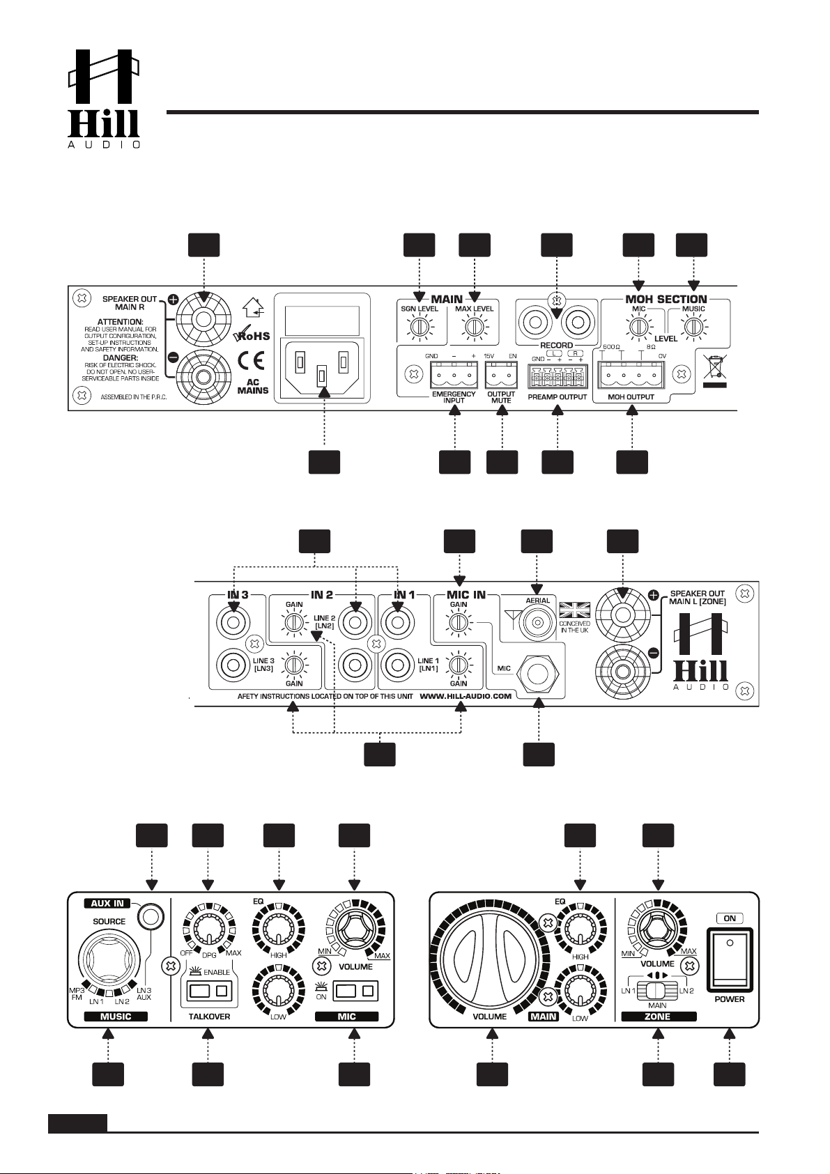
Output Mute connector. This is a terminal block input which allows to remotely mute all output
signals (Speakers, PreAmp) by simply shortening the contacts.
Emergency input. This is an auto-sensing, balanced terminal block input which allows the
connection to an emergency evacuation system. Once a signal is present on this input, all
output signals (Main, Zone) will be muted and the emergency message/signal from this input
will become audible instead. Please note that the internal microphone (14) is included in this
muting process and can not bet used while an emergency message is broadcasted.
Emergency volume control. This control allows to set the level with which the signal fed into the
emergency input (5) will be replayed on the speakers (2L&2R) and the Preamp output (7).
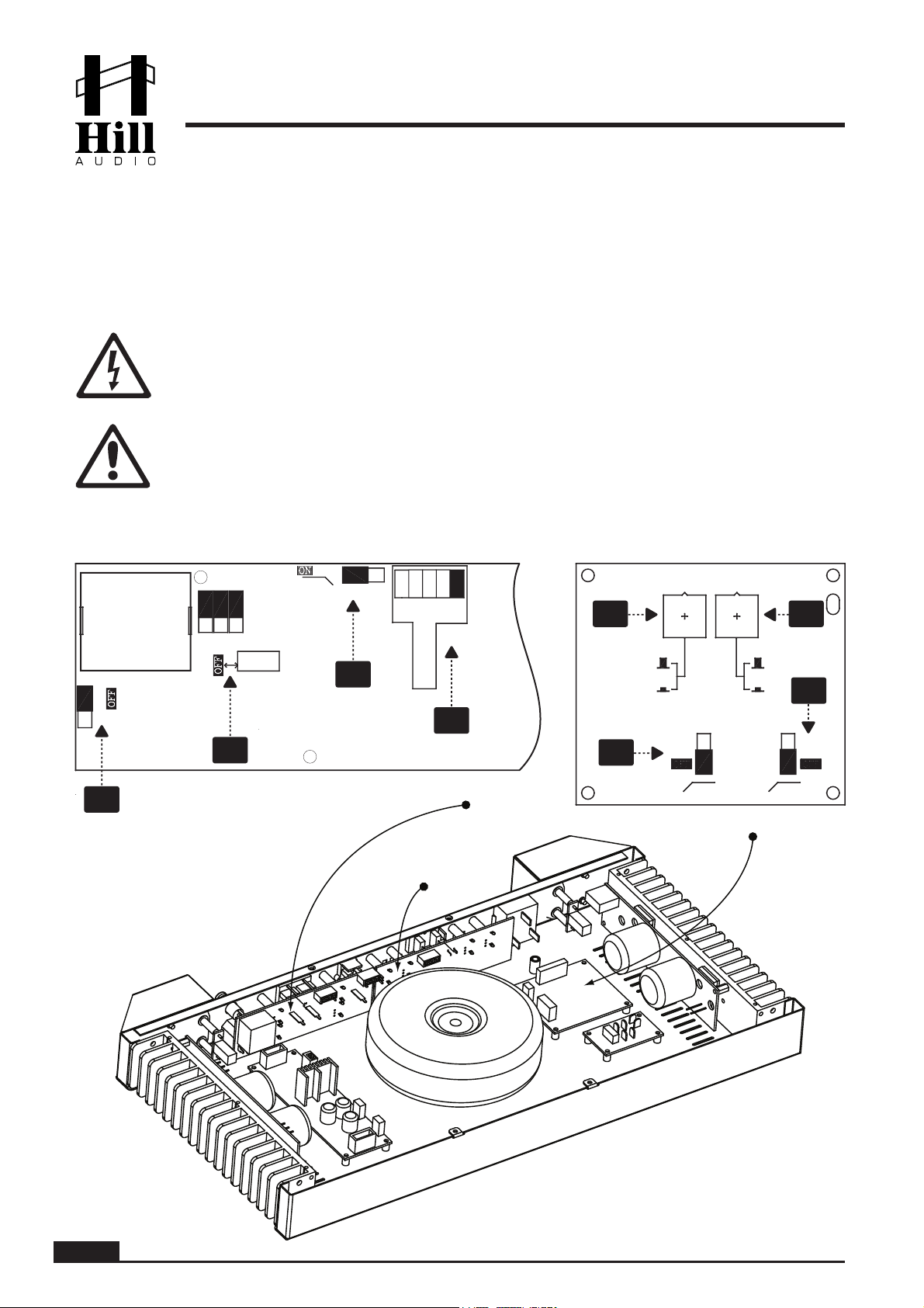
Preamp Output. This is terminal block which carries a balanced line level signal. The actual
signal depends on the internal setting on the AmpProcessing PCB (see chapter “setup infor-
mation”, switches A3 and A4). It may be the ZONE signal in stereo, controlled by the ZONE
volume control (26); it may be the MAIN signal in stereo, controlled by the MAIN volume
control (24), or it may be the ZONE signal in mono on one channel and the MAIN signal in
mono on the other channel, each controlled by their respective volume controls (24 | 26).
Record output. This is an unbalanced stereo output carrying the same signal as the main
output, but not influenced by the main volume control (24). This is normally used for recording
the output to an external tape, CD or memory device.
MOH Signal output. This output is designed to feed the music-on-hold (MOH) input of a
telephone system, which requires the built-in transformer isolation. The output can however
also be used as a monitor speaker output, providing 1W of output power into an 8 Ohm load
(do not use loads with lower impedance or higher power requirements). Both of these connec-
tion options are consolidated into one 4-pin terminal block connector. For connecting the MOH
input of a telephone system, use the two contacts labeled “600 Ohms”, which indicate the
transformer isolated output (nominal level 0dBu, with attenuated low frequency response). For
connecting to a monitor speaker, use the two contacts labeled “8 Ohm” and “0V”. The signal
present at the MOH output can be mixed by the two rear-side controls (10 & 11) from one
internally selectable music source and the microphone (for pure MOH purposes, the mic
volume shall be set to zero). The music source selection is expedited by internal jumpers (see
chapter “setup information”, jumper P4). Note that the front-panel controls of the unit have no
influence on the MOH signal, and that the Emergency and Music Mute functions are not affect-
ing the MOH output as well.
MOH Mic level control. Adjusts the microphone level contribution to the MOH signal (9). Turn
this control to zero for pure MOH applications.
MOH Music level control. Adjusts the music level contribution to the MOH signal (9). The music
signal source is selected by internal jumper P4 (see chapter “setup information”).
Line inputs. These RCA connectors provide inputs for line-level signals.
GAIN control for input channels. This allows the sensitivity (input gain) for every line input to be
adjusted, so that sources of different output level can be played at properly balanced levels.
Microphone input. This is a balanced ¼” TRS connector, which can be internally set to either
carry phantom power (+12V DC) or not, thus this input can be used both with condenser and
dynamic microphones (see chapter “setup information, jumper P1).
GAIN control for microphone input. This allows the sensitivity (input gain) for the input to be
adjusted to the microphone in use.
13
14
15