PAGE 8
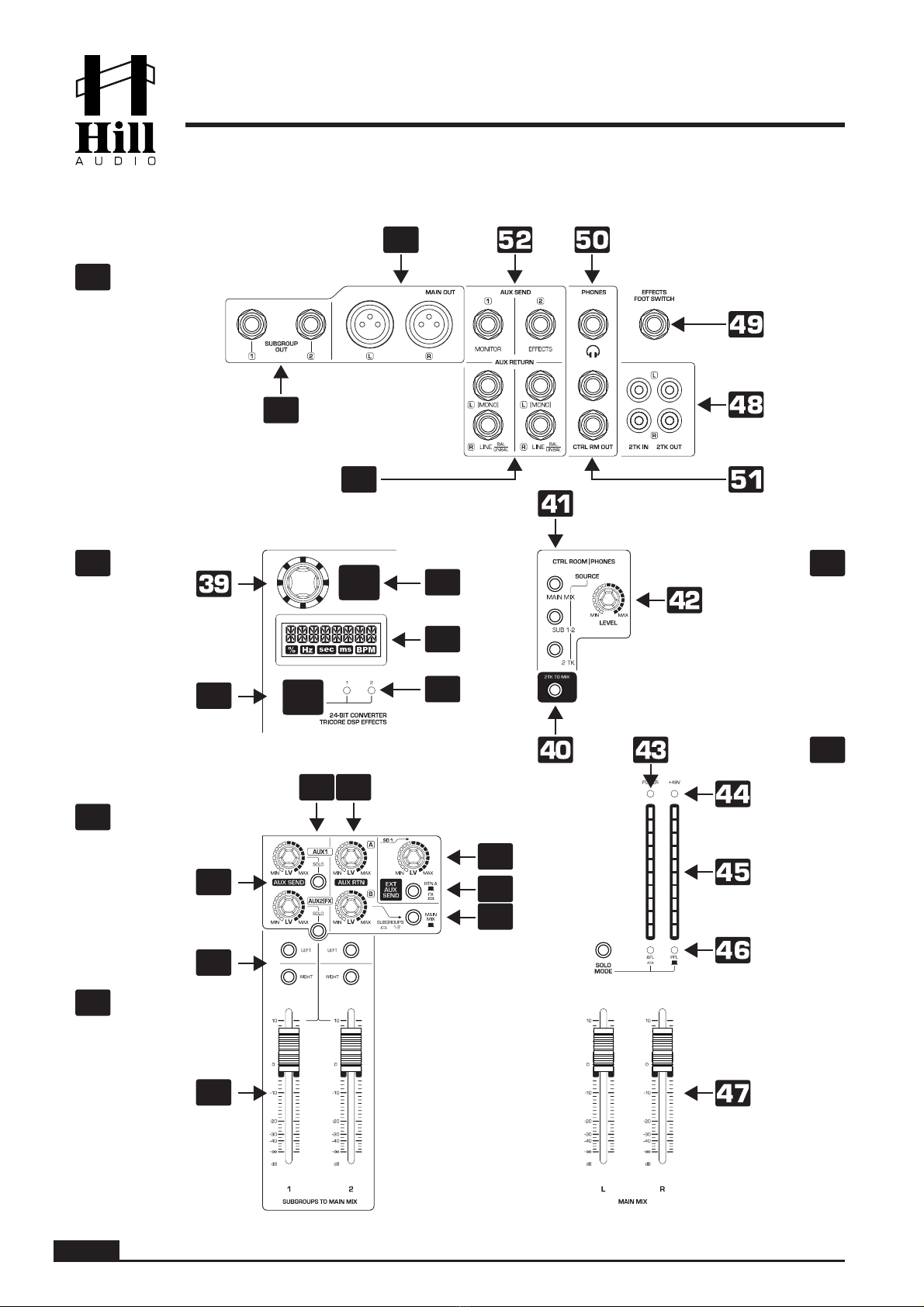
AUX SEND (1-2). These controls determine the overall output level of the AUX bus, with ratios
of the different channel contributions set by the channel AUX controls (12&14). The AUX bus
signal is then sent to either the external AUX SEND connectors (for AUX1) on the top panel
(section I) or to both the external AUX SEND connector on the top panel (section I) and the
internal effects processor (AUX 2).
AUX Send SOLO. Pressing any of these buttons will put the relative AUX Send into SOLO mode,
allowing to mute all sources on which SOLO is not selected, in one go. This helps to “isolate”
a specific source to make adjustments to the level or other settings.
AUX RETURN. This sets the level for the signals coming in through the top-panel RETURN
inputs (section I). Note these signals can both be mono or stereo, depending on the connected
sources in section I. If no source is connected to the AUX-RTN-B input on the top panel, then
RTN-B carries the output of the internal effects processor. Note that these inputs are inde-
pendent from the AUX SEND signal and might receive any signal, also others than what has
been sent through the relative AUX SEND. For RTN-A, it can also be fed back into SEND-1
respectively with the volume set by the control (31), if the selection switch (30) is not pressed.
EXTERNAL AUX SEND selector switch. This switch determines which signal is fed back into the
AUX-1 bus via the level control (31). Either the RTN-A or the internal effects can be chosen.
This allows to feedback either an externally or internally generated effect into the AUX-1 bus,
which due to its pre-fader routing primarily serves for monitoring purposes.
EXTERNAL AUX SEND volume control. Determines which level of the signal set by the selector
switch (30) is fed into the AUX-1 bus.
AUX-RETURN routing switches. While RTN-A goes straight to the main output, the routing for
RTN-B is more flexible. Aux Return B can be routed to the main mix or control room, and is
automatically routed to the output of the internal effects processor as well.
SUBGROUP ASSIGN switches. These switches assign any of the subgroups to either the left
or the right side of the master signal (or both). Please note that for the use of the PAN (15)
and BALANCE (26) controls in the input channels, it is assumed that subgroup 1 is routed to
the left side of the master, while subgroups 2 is routed to the right side of the master. If you
happen to set this switch (33) in a different manner, the left-right stereo imaging of a channel
may reverse.
SUBGROUP FADER. Determines the total level of the respective subgroup signal, both in the
main mix as well as at the subgroup outputs on the rear panel (section I).
EFFECTS PARAMETER button. The choice of the parameter to be edited can be made here,
the current parameter under editing is shown by the parameter indicators (36).
PARAMETER INDICATORS. Show which of the available parameters is chosen for editing via
the switch (35).
Effects processor display. Indicates all important information about the effects status.
EFFECTS TAP TEMPO button. This allows to tap along with the music to set a time-relevant
parameter (if available) in the chosen effect algorithm. For effects where no time-base param-
eter is available, this button is used to set a 3rd effects parameter. For all effects with a
tap-settable time base, the rear illumination of this button will flash with the speed of the set
timebase. See below algorithm table for more information.
28
30
29
27
33
31
32
34
35
36
37
38
USER MANUAL - LMR1204FX-C-(U) Rackmixer