PARK AUDIO DF -series User manual

Owner’s Manual
DF series
PROFESSIONAL FOUR CHANNEL
CLASS D POWER AMPLIFIER
DF2804MKII
R

ACCESSORIES
1. Power Cord 1pc.
2. Owner’s Manual 1pc.
3. Warranty 1pc.

CAUTION
RISK OF ELECTRIC SHOCK
DO NOT OPEN
AVIS
RISQUE DE CHOC ELECTRIQUE
NE PAS OUVRIR
CAUTION! The amplifier runs on 230V AC voltage. Removing the cover will expose
you to a potentially dangerous voltage! Do not use the unit if the electrical power cord is
frayed or broken.
Power is supplied from 230V AC single-phase grounded 50/60 Hz source!
CAUTION! The amplifier can yield dangerous output voltage! Do not touch the non-
insulated cable parts, connected to the unit in operation!
CAUTION! The high sound pressure level of speaker systems generated by high
output power, delivered by the amplifier, may be hazardous to your hearing. Please,
take adequate safety precautions.
WARNING! The amplifier yields high output power. The manufacturer shall not be held
responsible for any damage to the speakers caused by excessive power from the unit.
WARNING SIGNS:
Important information!
Intended to warn the user about any important applicable information
contained in this Owner’s Manual.
Hazardous voltage inside!
Intended to warn the user about electric shock hazard due to high voltage
inside the product.

GENERAL
The DF2804MkII professional class D four-channel amplifier is designed for high
fidelity amplification of sound signals within a professional sound reproduction system.
The amplifier can be operated in a four-channel mode, three-channel mode (one pair of
channels bridged) or two-channel mode (both pairs of channels bridged).
To ensure the most advantageous and faultless operation of the amplifier, please,
read this Manual before use.
UNPACKING
The manufacturer’s quality control system provides for careful examination of
each product before it leaves the factory to ensure its flawless appearance. After
unpacking, please, check the unit for any physical damage. In case of damage, please,
contact your local dealer. Keep the shipping carton and all packing material as you may
need them for reshipment of the unit.
2

3
DESIGN FEATURES
Physical Design
The amplifier is enclosed in a metal (steel) case of 88 mm (2U) height. The
amplifier is designed to be standard rack-mounted (RACK 19").
Power Supply Unit
All four channel of the amplifier share the same pulse power supply unit.
Cooling System
The amplifier features a forced cooling system which is common for all four
channels. The amplifier and the power supply unit are cooled with a single fan blowing
front to rear. The cooling system provides for a double-step intensity-cooling rate
switching. At a normal temperature, the fan runs at a low speed, thus generating the
least noise possible. When the amplifier is set to deliver a high output power or when
the ambient temperature is higher than normal, the cooling system may switch the fan
to the other (higher) cooling rate.
Output Stage
The output stage of this power amplifier is designed according to Class D
technology to deliver high efficiency and least heat. The high switching rate ensures the
high sound quality comparable with the best analogue amplifiers.
Balanced Inputs
The use of balanced inputs provides for an essential reduction of the environment-
induced hum and noise interference with long input connecting cables.
Line Outputs
The amplifier line outputs are parallel to the inputs (each along the respective
channel) and provide for parallel connection of several amplifiers with standard signal
cables using XLR connectors.
Mode switch
3-position slide switch for each pair of channels.
Operating modes available:
– STEREO – two channels drive two separate loads from two separate signal sources;
– MONO – two channels drive two separate loads from a single input signal source;
– BRIDGE – two channels drive a common load from a single signal source.
Mode switches are located on the rear panel.
Input Filter
To improve the performance of loudspeakers, the amplifier incorporates a switch-
selectable high-pass 4-th order filter with 24dB per octave slope rate. This is the filter
recommended by all major loudspeakers manufacturers. This filter cuts off any signals
below 45Hz, which generally cannot be reproduced by most of the professional
loudspeakers.
The filter significantly reduces the travel of the LF speaker cone below the
loudspeaker frequency cut-off point (which is especially good for phase-inversion
loudspeakers) thus making it possible to increase the power applied to the LF speaker
without any danger of its overheating. The power of the amplifier is not wasted for cone
flapping and allows the loudspeaker to achieve higher sound pressure.

When it is necessary to achieve a linear frequency response to drive full-range
loudspeakers, generally used in studios or in cinema theatres, the input filter can be
disabled (bypassed for each channel individually) with the slide switches located on the
amplifier rear panel.
Below see the enabled and disabled filter low frequency response diagrams.
20Hz 50Hz 100Hz 200Hz 900Hz
-10
-5
0
5
10
ON (45Hz)
20Hz 50Hz 100Hz 200Hz 900Hz
-10
-5
0
5
10
OFF
Built-in Two-Way Crossover
This feature is to save your money and effort when driving two-way loudspeakers.
The frequency range (high, low, full range signal) is selected individually for each
channel with a slide switch. The crossover frequency point is factory preset (generally
to 125Hz). However, it can be changed by replacing the crossover PCB.
Input Level Attenuators
These allow setting the amplifier to the required sensitivity (each channel
individually) which is very helpful when several amplifiers are used to drive different
types of loudspeakers or are used within multi-speaker sound reinforcement systems.
The attenuators are located on the front panel.
Optoelectronic Clip-Limiter
The Clip-limiter is to reduce the input signal level as soon as any emergency or
overload occurs to prevent any sound distortion.
Detachable Power Cord
This feature is provided for convenience of transportation and rack mounting.
4

5
FUNCTIONAL FEATURES
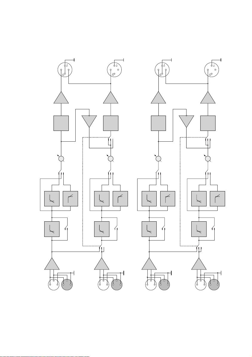
Overload and Short-Circuit Protection
Individual per each channel. This protective system becomes active in case of
short-circuited output or overload, caused by reduced load impedance. It disables the
output signal of the respective channel for 0.5 second and then the amplifier gradually
resumes its delivery.
DC Output Protection
The amplifier schematics precludes any clicks or noise occurring during the
power-on/off transition processes without utilizing any relay, commonly used for
connecting the output signal to a loudspeaker. To prevent any DC damage to
loudspeakers, the amplifier incorporates the triak protection system for each channel,
which short-circuits the amplifier output in case of DC voltage or powerful LF
fluctuations.
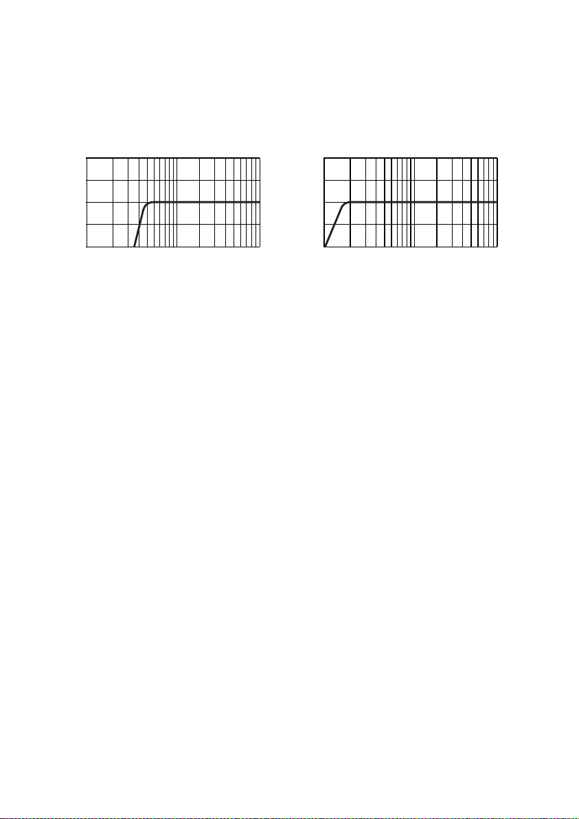
High Frequency Protection
Should any powerful high frequency fluctuations occur on the output either as a
result of poor contact in the input cable connectors, or being send to the amplifier’s input
by any other device (such as a crossover or mixing console), the protection system
activates the built-in optoelectronic Clip-limiter to reduce the input signal level. Thus the
protection system effectively prevents any damage to tweeters as might be caused by
non-musical signals of powerful high frequency spectrum.
Thermal Protection
The continuous-operation-support protection system is common for four
channels. When the heat sink becomes heated over 50°С, the fan goes into its
maximum speed mode (normally, the fan runs at its minimum at a low speed). If the
temperature of the heat sink rises further to 65°С, the next stage of the thermal
protection system goes active. It is a built-in Clip-limiter, which reduces the input signal
level (for all channels at a time) without distorting the amplified signal. In this case the
thermal protection LED becomes slightly lit (dim). The higher the temperature, the
lower signal level, the brighter is the LED. Such an algorithm ensures faultless and
continuous functioning of the amplifier even in case of overheating.
The amplifier may stop functioning only in case of the fan breakdown or blocked
air flow. In this case upon reaching 85°С, the independent protection system disables
the respective channel of the amplifier. The CLIP LED goes on and the SIGNAL LED of
the affected channel goes off. The amplifier resumes its operation in the reverse order.
As soon as the amplifier cools down, the affected channels gradually regain their
amplification level up to the set value.
Soft Signal Start
During the power-on process, this feature ensures smooth gain from zero to the
maximum level to provide for a smooth rise of the sound level, emitted from the
loudspeakers.

BLOCK DIAGRAM
6
1+
HF
LF TOP
THRU
SUB
CROSSOVER
CH 1
INPUT
ON
OFF
HI PASS FILTER
(45 Hz)
45Hz
150Hz
150Hz
HF
LF
CH 2
ON
OFF
HI PASS FILTER
(45 Hz) 150Hz
150Hz
MONO
STEREO
BRIDGE
MODE
Power
amplifier
Limiter
Power
amplifier
Limiter
45Hz
1+
2+
2+
SPEAKER
OUTPUT
THRU
INPUT
THRU
TOP
THRU
SUB
CROSSOVER
LEVEL
LEVEL
1+
HF
LF TOP
THRU
SUB
CROSSOVER
CH 3
INPUT
ON
OFF
HI PASS FILTER
(45 Hz)
45Hz
150Hz
150Hz
HF
LF
CH 4
ON
OFF
HI PASS FILTER
(45 Hz) 150Hz
150Hz
MONO
STEREO
BRIDGE
MODE
Power
amplifier
Limiter
Power
amplifier
Limiter
45Hz
1+
2+
2+
THRU
INPUT
THRU
TOP
THRU
SUB
CROSSOVER
LEVEL
LEVEL
Ch1, Ch2,
Bridge Ch1-Ch2
SPEAKER
OUTPUT
Ch2
SPEAKER
OUTPUT
Ch3, Ch4,
Bridge Ch3-Ch4
SPEAKER
OUTPUT
Ch4

FRONT PANEL
THERMAL – overheating alarm LED.
Brightness depends on the temperature of the heat sink (See: Thermal
Protection).
POWER LED.
LED goes off when the DC output protection system activated.
CLIP – clip LEDs for Channels 1, 2, 3 and 4, respectively.
They indicate:
– overload condition causing distortion;
– activation of thermal protection system which disables the respective
channel (the SIGNAL LED goes off). (See: Thermal Protection).
SIGNAL LEDs, indicating output signal on Channels 1, 2, 3 and 4,
respectively.
LEVEL – input (sensitivity) level attenuators for Channels 4, 3, 2 and 1,
respectively.
POWER switch.
3
4
11
5
6
12
7
8
13
1
2
9
10
14
15
7
1112131415
135
42 6 8 10
79
DF2 804
P RO F ES SI ON A L P O WE R A MP LI FI ER

REAR PANEL
THRU – line outputs for сhannels 4, 3, 2, 1, respectively (XLR male).
Are used to deliver input signal along the respective channel to the input of
another amplifier.
THRU connectors are parallel to INPUT connectors of respective channels.
INPUT – balanced inputs (XLR female) channels 4, 3, 2, 1, respectively.
Inputs for сhannels 1, 3 are also used to supply the input signal for channels
1, 2 and channels 3, 4 functioning in the MONO and BRIDGE mode.
MODE switch for channel 3 and 4:
– MONO – channels 3, 4 drive two loads from a single input signal source;
– STEREO – channels 3, 4 drive two loads from two separate input signal
sources;
– BRIDGE – channels 3, 4 drive a common load from a single input signal
source.
MODE switch for channels 1 and 2:
– MONO – channels 1, 2 drive two loads from a single input signal source;
– STEREO – channels 1, 2 drive two loads from two separate input signal
sources;
– BRIDGE – channels 1, 2 drive a common load from a single input signal
source.
MAINS IN – power cord socket for 230V AC 50/60Hz grounded mains.
CROSSOVER switches for channels 4, 3, 2 and 1, respectively, to select the
required frequency band:
– TOP – higher frequency signal component;
– SUB – lower frequency signal component;
– THRU (Full Range).
Switches for channels 1, 3 are also used to select the required frequency
band for channels 1, 2 and channels 3, 4 functioning in the BRIDGE mode.
2 4 7 9
11
12
17
18
23
1 5 6
10
3
8
8
TO REDUCE THE RISK OF FIRE OR ELECTRIC SHOCK
DO NOT EXPOSE THIS EQUIPMENTTO RAIN OR MOISTURE.
DO NOT REMOVE COVER.
NO USER SERVICEABLE PARTS INSIDE.
REFER SERVICING TO QUALIFIED SERVICE PERSONNEL.
WARNING
INPUT INPUT
PUSH PUSH
MODE
CH3
CH 3-4
CH4
THRU
MONO
STEREO
BRIDGE
THRU
OFF
CROSSOVER
THRU
CH 4
CH 3
OUTPUT
4 min
BRIDGE
8 min
ON OFF ON CROSSOVER
THRU
1
2
1
2
1
2
4 min
Use INPUT CH3
for MONO
& BRIDGE MODE
CH 4
4 min
1
1
INPUT INPUT
PUSH PUSH
MODE
CH1
CH 1-2
CH2
THRU
MONO
STEREO
BRIDGE
THRU
OFF
CROSSOVER
THRU
CH 2
CH1
OUTPUT
4 min
BRIDGE
8 min
ON OFF ON CROSSOVER
THRU
1
2
1
2
1
2
4 min
Use INPUT CH3
for MONO
& BRIDGE MODE
CH 2
4 min
1
1
MAINS IN
RISK OF ELECTRIC SHOCK
CAUTION
DO NOT OPEN
5671 2 3 4
21
2223
11
20
19 18
15
1617
14
13 12
10
8 9
PROFESSIONAL POWER AMPLIFIER
model DF2804 MkII
230V 50/60Hz 1100VA
Serial No
Park Audio II, Ltd M ade i n U kraine

9
OUTPUT – SpeakON output connectors for channels 1, 2, 3, 4, respectively,
used to link up to loudspeakers.
To link up loudspeakers to channels 1, 2 and 3, 4 functioning in the BRIDGE
mode, use outputs for channels 1 and 3, respectively.
In addition, channel 1 output connector is interlinked with channel 2 output,
while channel 3 output connector with channel 4 output, thus making it
possible to use a single NL4FC connector (wired accordingly) to connect
channel 1 and 2 loudspeakers to channel 1 output connector and channel 3
and 4 loudspeakers to channel 3 output connector.
HI PASS FILTER switches for channels 1, 2, 3, 4, respectively, used to
enable/disable (bypass) the input filter for each channel individually.
12
16
19
22
14
15
20
21

CABLE REQUIREMENTS
Input Cables
Make sure to use only shielded cables whether balanced or unbalanced.
Shielding, when properly grounded, protects a signal against external electrical
interference.
As a rule, unbalanced lines over 3 meters long are not acceptable. Greater
distances require a balanced cable. Avoid placing input cables close to power cords or
power transformers.
Output Cables
The amplifier is capable of delivering high level output current; therefore, the wire
gauge used for speaker cables is particularly important. Inadequate wire gauge adds
significant resistance to the speaker’s own impedance, reducing the power, which is
actually delivered to the speaker. It will also result in a decreased damping factor and
possible fire hazard.
Since the power, applied to the loudspeaker, is of primary concern in system
design, we have included the table below to allow you determine the appropriate wire
gauge for your application.
Power Loss in a 10-meter Cable
The table shows the percentage of the power loss in a 10-meter copper multiple-
core cable. This table reflects the power loss as a percentage of the output power of the
amplifier applied to the load. Use this table to determine the power loss to the load at
other cable lengths. For example, if you plan to deliver 100 Watts to 8-Ohm load
2
through 20-m cable of 0.75-mm gauge, the power loss in the cable would be 5.8% x
2=11.6% of 100W or 11.6W lost in the cable.
2
0.50mm
2
0.75mm
2
1.00mm
2
1.50mm
2
2.00mm
2
2.50mm
2
4.00mm
0.72 Ohm
0.49 Ohm
0.36 Ohm
0.24 Ohm
0.18 Ohm
0,15 Ohm
0.09 Ohm
15.4 %
10.9 %
8.3 %
5.7 %
4.3 %
3.6 %
2.3 %
8.3 %
5.8 %
4.3 %
2.9 %
2.2 %
1.8 %
1.1 %
Wire Gauge Cable
Resistance Cable Power Loss
4 Ohm Load 8 Ohm Load
10

INPUT AND OUTPUT CONNECTORS
Input Connectors
Use XLR (male) connectors to connect to the amplifier inputs and XLR (female)
connectors to line outputs.
See the wiring on the figures below.
Output Connectors
Use SpeakON NL2FC or NL4FC connectors to connect loudspeakers to the
amplifier individual channel outputs. For bridged connection or connection of two
channels via a single cable, use SpeakON NL4FC.
See the wiring on the figures below.
CAUTION! Never attempt to jumper or otherwise link up any pins of output
connectors.
21
3
2 1
3
-
1
1+
-
1
2+
1+
-
2
-
1
2+
1+
-
2
-
1
2+
1+
-
2
XLR (male) XLR (female)
Cold « – »
Shield (Ground)
Hot « + »
Cold « – »
Hot « + »
Shield (Ground)
NL2FC for individual channel mode
Output (+)
Output (–)
NL4FC or bridge mode
(only for Channels 1 & 3 connectors)
Output (+)
Output (–)
NL4FC for individual channel mode
Output (+)
Output (–)
NL4FC for linking up two channels
with a single connector
(only for Channels 1 & 3 connectors)
Channel 1 (3)
Output (+)
Channel 1 (3)
Output (–)
Channel 2 (4)
Output (–)
Channel 2 (4)
Output (+)
11

RACK-MOUNTING REQUIREMENTS
The amplifier is designed to fit a standard 19” rack. While mounting, make sure to
provide unhindered air access to the front and rear sides of the rack. Fan direction is
from front to back. It is not necessary to leave empty space above or below the
amplifier.
For stationary use, it will be enough to fix securely only the front panel of the
amplifier to the rack. However, never attempt to transport the unit unless its rear end is
properly supported and/or securely fixed, as it may be fraught with danger of damage.
AC POWER REQUIREMENTS
The amplifier is supplied with a three-conductor grounded AC power cord, and
should be plugged into a standard 3-wire grounded electrical outlet, which supplies
230VAC 50/60Hz. In the event of line voltage sag, the unit will continue to operate
normally, albeit with less power. The mains lower voltage limit for the amplifier to retain
its operability is 160V.
The amplifier is connected to the mains via cable, supplied with the amplifier.
When connecting to mains, make sure that no other devices with high power
consumption are connected to it, as the normal operation of several such devices may
be impossible.
The actual AC current consumption depends on the audio signal level and the load
impedance. For typical audio program material the amplifier, driving all channels at
nominal impedance (4Ohms), just peaking at the clipping level, has the average power
consumption is 4.8A*, which must be noted for system design purposes.
In order to reduce the AC hum, please, plug all sound equipment, interconnected
with signal cables, into the same power mains outlet.
12

OPERATING MODES
Four-Channel Mode for Four Individual Signal Sources
STEREO mode is used for both pairs of the channels.
13
Link up an input signal to each individual channel.
Connect a loudspeaker to each channel output with a SpeakON NL2FC or
NL4FC connector.*
Set the MODE switches for Channels 1 & 2 and Channels 3 & 4 to STEREO.
Adjust the input signal level for each channel individually with the LEVEL
attenuators on the front panel.
Set the CROSSOVER switch of each individual channel to the required position.
Generally, it is recommended to set the input HI PASS FILTER switches to 45Hz.
However, when it is necessary to obtain a linear frequency response to drive full-range
systems used in studios or cinema theatres, set them to OFF. See: Input Filter.
Note.
* The loudspeaker rated impedance should be at least 4Ohm.
Never attempt to jumper or otherwise link up any pins of SpeakON output connectors.
TO REDUCE THE RISK OF FIRE OR ELECTRIC SHOCK
DO NOT EXPOSE THIS EQUIPMENT TO RAIN OR MOISTURE.
DO NOT REMOVE COVER.
NO USER SERVICEABLE PARTS INSIDE.
REFER SERVICING TOQUALIFIED SERVICE PERSONNEL.
WARNING
INPUT INPUT
PUSH PUSH
MODE
CH3
CH 3-4
CH4
THROUGH
MONO
STEREO
BRIDGE
THROUGH
OFF
CROSSOVER
THRU
CH 4
CH 3
OUTPUT
4 min
BRIDGE
8 min
ON OFF ON CROSSOVER
THRU
1
2
1
2
1
2
4 min
Use INPUT CH3
for MONO
& BRIDGE MODE
CH 4
4 min
1
1
INPUT INPUT
PUSH PUSH
MODE
CH1
CH 1-2
CH2
THROUGH
MONO
STEREO
BRIDGE
THROUGH
OFF
CROSSOVER
THRU
CH 2
CH1
OUTPUT
4 min
BRIDGE
8 min
ON OFF ON CROSSOVER
THRU
1
2
1
2
1
2
4 min
Use INPUT CH3
for MONO
& BRIDGE MODE
CH 2
4 min
1
1
MAINS IN
RISK OF ELECTRIC SHOCK
CAUTION
DO NOT OPEN
1-
1+
To Input Signal Sources
To Loudspeakers
MODE CH 3-4
switch is set to
STEREO
MODE CH 1-2
switch is set to
STEREO
PROFESSIONAL POWER AMPLIFIER
model DF2804 MkII
230V 50/60Hz 1100VA
Serial No
Park Audio II, Ltd M ade i n U kraine

Four-Channel Mode for Two Signal Sources
MONO mode is used for both pairs of the channels.
Apply an input signal to the inputs of Channels 1 and 3.
Connect a loudspeaker to each channel output with a SpeakON NL2FC or
NL4FC connector.*
Set the MODE switches for Channels 1 & 2 and Channels 3 & 4 to MONO.
Adjust the input signal level for each channel individually with the LEVEL
attenuators on the front panel.
Set the CROSSOVER switch of each individual channel to the required position.
Generally, it is recommended to set the input HI PASS FILTER switches to 45Hz.
However, when it is necessary to obtain a linear frequency response to drive full-range
systems used in studios or cinema theatres, set them to OFF. See: Input Filter.
Note.
* The loudspeaker rated impedance should be at least 4Ohm.
Never attempt to jumper or otherwise link up any pins of SpeakON output connectors.
14
TO REDUCE THE RISK OF FIRE OR ELECTRIC SHOCK
DO NOT EXPOSE THIS EQUIPMENTTO RAIN OR MOISTURE.
DO NOT REMOVE COVER.
NO USER SERVICEABLE PARTS INSIDE.
REFER SERVICING TO QUALIFIED SERVICE PERSONNEL.
WARNING
INPUT INPUT
PUSH PUSH
MODE
CH3
CH 3-4
CH4
THROUGH
MONO
STEREO
BRIDGE
THROUGH
OFF
CROSSOVER
THRU
CH 4
CH 3
OUTPUT
4 min
BRIDGE
8 min
ON OFF ON CROSSOVER
THRU
1
2
1
2
1
2
4 min
Use INPUT CH3
for MONO
& BRIDGE MODE
CH 4
4 min
1
1
INPUT INPUT
PUSH PUSH
MODE
CH1
CH 1-2
CH2
THROUGH
MONO
STEREO
BRIDGE
THROUGH
OFF
CROSSOVER
THRU
CH 2
CH1
OUTPUT
4 min
BRIDGE
8 min
ON OFF ON CROSSOVER
THRU
1
2
1
2
1
2
4 min
Use INPUT CH3
for MONO
& BRIDGE MODE
CH 2
4 min
1
1
MAINS IN
RISK OF ELECTRIC SHOCK
CAUTION
DO NOT OPEN
1-
1+
To Input Signal Sources
To Loudspeakers
MODE CH 3-4
switch is set to
MONO
MODE CH 1-2
switch is set to
MONO
PROFESSIONAL POWER AMPLIFIER
model DF2804 MkII
230V 50/60Hz 1100VA
Serial No
Park Audio II, Ltd M ade i n U kraine

15
Two-Channel Mode
Both pairs of channels are bridged.
Apply an input signal to the inputs of Channels 1and 3.
Connect a loudspeaker to the output of Channels 1 and 3 with a SpeakON
NL4FC connector wired for bridge connection.*
Set the MODE switches for Channels 1 & 2 and Channels 3 & 4 to BRIDGE.
Adjust the input signal level with the LEVEL attenuators for Channels 1 and 3.
Set the CROSSOVER switches of Channels 1 and 3 to the position required for
each pair of channels (the crossover switches of Channels 2 and 4 may be in any
position).
Generally, it is recommended to set the input HI PASS FILTER switches to 45Hz
(in this case only switches for Channels 1 and 3 are involved). However, when it is
necessary to obtain a linear frequency response to drive full-range systems used in
studios or cinema theatres, set them to OFF. See: Input Filter.
Note.
* The loudspeaker rated impedance should be at least 8Ohm.
Never attempt to jumper or otherwise link up any pins of SpeakON output connectors.
TO REDUCE THE RISK OF FIRE OR ELECTRIC SHOCK
DO NOT EXPOSE THIS EQUIPMENTTO RAIN OR MOISTURE.
DO NOT REMOVE COVER.
NO USER SERVICEABLE PARTS INSIDE.
REFER SERVICING TO QUALIFIED SERVICE PERSONNEL.
WARNING
INPUT INPUT
PUSH PUSH
MODE
CH3
CH 3-4
CH4
THROUGH
MONO
STEREO
BRIDGE
THROUGH
OFF
CROSSOVER
THRU
CH 4
CH 3
OUTPUT
4 min
BRIDGE
8 min
ON OFF ON CROSSOVER
THRU
1
2
1
2
1
2
4 min
Use INPUT CH3
for MONO
& BRIDGE MODE
CH 4
4 min
1
1
INPUT INPUT
PUSH PUSH
MODE
CH1
CH 1-2
CH2
THROUGH
MONO
STEREO
BRIDGE
THROUGH
OFF
CROSSOVER
THRU
CH 2
CH1
OUTPUT
4 min
BRIDGE
8 min
ON OFF ON CROSSOVER
THRU
1
2
1
2
1
2
4 min
Use INPUT CH3
for MONO
& BRIDGE MODE
CH 2
4 min
1
1
MAINS IN
RISK OF ELECTRIC SHOCK
CAUTION
DO NOT OPEN
To Input Signal Sources
To Loudspeakers
MODE CH 3-4
switch is set to
BRIDGE
MODE CH 1-2
switch is set to
BRIDGE
2+
1+
PROFESSIONAL POWER AMPLIFIER
model DF2804 MkII
230V 50/60Hz 1100VA
Serial No
Park Audio II, Ltd M ade i n U kraine

Three-Channel Mode (Option 1)
Using the bridge mode for one pair of channels and the individual mode for the
other.*
Apply an input signal to the inputs of Channels 1, 3 and 4.
Connect loudspeakers to the output of Channel 1 with a SpeakON NL4FC
connector wired for bridge connection and to the outputs of Channel 3 and 4 with
SpeakON NL2FC or NL4FC connectors wired individual-channel mode. **
Set the MODE switches for Channels 1 & 2 to BRIDGE and for Channels 3 & 4 to
STEREO.
Adjust the input signal level with the LEVEL attenuators for Channels 1, 3 and 4.
Set the CROSSOVER switches of Channel 1, 3 and 4 to the required position (the
crossover switch of Channel 2 may be in any position).
Generally, it is recommended to set the input HI PASS FILTER switches to 45Hz
(in this case only switches for Channel 1, 3 and 4 are involved). However, when it is
necessary to obtain a linear frequency response to drive full-range systems used in
studios or cinema theatres, set them to OFF. See: Input Filter.
Note.
* Any pair of channels (1 & 2 or 3 & 4) can be operated in the bridge mode or individual mode if
properly connected and set up.
** The loudspeaker rated impedance should be at least 4Ohm for individual connection and 8Ohm
for bridge connection.
16
TO REDUCE THE RISK OF FIRE OR ELECTRIC SHOCK
DO NOT EXPOSE THIS EQUIPMENT TO RAIN OR MOISTURE.
DO NOT REMOVE COVER.
NO USER SERVICEABLE PARTS INSIDE.
REFER SERVICING TO QUALIFIED SERVICE PERSONNEL.
WARNING
INPUT INPUT
PUSH PUSH
MODE
CH3
CH 3-4
CH4
THROUGH
MONO
STEREO
BRIDGE
THROUGH
OFF
CROSSOVER
THRU
CH 4
CH 3
OUTPUT
4 min
BRIDGE
8 min
ON OFF ON CROSSOVER
THRU
1
2
1
2
1
2
4 min
Use INPUT CH3
for MONO
& BRIDGE MODE
CH 4
4 min
1
1
INPUT INPUT
PUSH PUSH
MODE
CH1
CH 1-2
CH2
THROUGH
MONO
STEREO
BRIDGE
THROUGH
OFF
CROSSOVER
THRU
CH 2
CH1
OUTPUT
4 min
BRIDGE
8 min
ON OFF ON CROSSOVER
THRU
1
2
1
2
1
2
4 min
Use INPUT CH3
for MONO
& BRIDGE MODE
CH 2
4 min
1
1
MAINS IN
RISK OF ELECTRIC SHOCK
CAUTION
DO NOT OPEN
1-
1+
To Input Signal Sources
To Loudspeakers
MODE CH 3-4
switch is set to
STEREO
MODE CH 1-2
switch is set to
BRIDGE
2+
1+
PROFESSIONAL POWER AMPLIFIER
model DF2804 MkII
230V 50/60Hz 1100VA
Serial No
Park Audio II, Ltd M ade i n U kraine

17
Three-Channel Mode (Option 2)
Using the bridge mode for one pair of channels and the individual mode for the
other.*
Apply an input signal to the inputs of Channel 1 and 3.
Connect loudspeakers to the output of Channel 1 with a SpeakON NL4FC
connector wired for bridge connection and to the outputs of Channel 3 and 4 with
SpeakON NL2FC or NL4FC connectors wired individual-channel mode. **
Set the MODE switches for Channels 1 & 2 to BRIDGE while for Channels 3 & 4 to
MONO.
Adjust the input signal level with the LEVEL attenuators for Channels 1, 3 and 4.
Set the CROSSOVER switches of Channel 1, 3 and 4 to the required position (the
crossover switch of Channel 2 may be in any position).
Generally, it is recommended to set the input HI PASS FILTER switches to 45Hz
(in this case only switches for Channel 1, 3 and 4 are involved). However, when it is
necessary to obtain a linear frequency response to drive full-range systems used in
studios or cinema theatres, set them to OFF. See: Input Filter.
Note.
* Any pair of channels (1 & 2 or 3 & 4) can be operated in the bridge mode or individual mode if
properly connected and set up.
** The loudspeaker rated impedance should be at least 4Ohm for individual connection and 8Ohm
for bridge connection.
TO REDUCE THE RISK OF FIRE OR ELECTRIC SHOCK
DO NOT EXPOSE THIS EQUIPMENTTO RAIN OR MOISTURE.
DO NOT REMOVE COVER.
NO USER SERVICEABLE PARTS INSIDE.
REFER SERVICING TO QUALIFIED SERVICE PERSONNEL.
WARNING
INPUT INPUT
PUSH PUSH
MODE
CH3
CH 3-4
CH4
THROUGH
MONO
STEREO
BRIDGE
THROUGH
OFF
CROSSOVER
THRU
CH 4
CH 3
OUTPUT
4 min
BRIDGE
8 min
ON OFF ON CROSSOVER
THRU
1
2
1
2
1
2
4 min
Use INPUT CH3
for MONO
& BRIDGE MODE
CH 4
4 min
1
1
INPUT INPUT
PUSH PUSH
MODE
CH1
CH 1-2
CH2
THROUGH
MONO
STEREO
BRIDGE
THROUGH
OFF
CROSSOVER
THRU
CH 2
CH1
OUTPUT
4 min
BRIDGE
8 min
ON OFF ON CROSSOVER
THRU
1
2
1
2
1
2
4 min
Use INPUT CH3
for MONO
& BRIDGE MODE
CH 2
4 min
1
1
MAINS IN
RISK OF ELECTRIC SHOCK
CAUTION
DO NOT OPEN
1-
1+
To Input Signal Sources
To Loudspeakers
MODE CH 3-4
switch is set to
MONO
MODE CH 1-2
switch is set to
BRIDGE
2+
1+
PROFESSIONAL POWER AMPLIFIER
model DF2804 MkII
230V 50/60Hz 1100VA
Serial No
Park Audio II, Ltd M ade i n U kraine

TROUBLESHOOTING
No Sound Signal on the Amplifier’s Output
POWER LED is OFF:
– damaged power cable;
– no power;
– DC protection mode.
But for POWER LED all other LEDs are OFF:
– no input signal;
– input level attenuators are set to minimum position.
SIGNAL and CLIP LEDs are occasionally blinking:
– output cable is short-circuited;
– load impedance is too low.
THERMAL LED and one or several CLIP LEDs are ON while SIGNAL LEDs of
these same channels are OFF:
– the respective channels are in the overheating protection mode (the heat
sink temperature is over 85°С).
Reduced Output Signal Level
THERMAL LED is slightly lit:
– the unit is protected against overheating (heat sink temperature has exceeded
65°С thus activating the thermal protection system).
Sound Distortion
Only SIGNAL LED is ON:
– applied input signal is distorted before it gets to the amplifier;
– loudspeakers are damaged.
If input level attenuators are set close to their minimum position, distortion
may occur as a result of input stage overload with high input signal.
Both SIGNAL and CLIP LEDs are ON:
– overload caused by low load impedance or too high input signal level.
Hum and Interference
Make sure to have the power cord 3-wire plug properly connected to a grounded
outlet. Disconnecting the ground contact usually does not eliminate hum and
interference but may pose a risk of electric shock.
To reduce hum and noise, use balanced connections.
Interference can also be caused by lighting intensity controls (dimmers), as well
as by neon or luminescent tubes.
18
This manual suits for next models
1
Table of contents
Other PARK AUDIO Power Amplifier manuals