Newhank D4000 User manual

Model: D4000
ON/ OFF
POWER
-inf 0
-inf 0
-inf 0
-inf 0
-inf 0
-inf 0
-inf 0
-inf 0
D4000D4000

Page 9
CAUTION
RISK OF ELECTRIC SHOCK
DO NOT OPEN
!
Important Safety Instructions
1. Read these instructions.
2. Keep these instructions.
3. Heed all warnings.
4. Follow all instructions.
5. Do not usethis apparatus near water.
6. Clean only witha dry cloth.
7. Do not blockany ventilation opening. Installin accordance with the
manufacturer`s instructions.
8. Do not installnear any heat source such as radiator ,heatregister,
stove, or other apparatus(includingamplifier )that produce heat.
9. Do not defeatthe safety purpose ofthe polarized or grounding-type
plug. A polarized plughas two blades withone wider than theother.
A grounding-type plug hastwo blades and athird grounding prong.
The wide blade orthe third prong isprovided for your safety. If the
provided plug does notft into your socket,consult an electrician for
replacement of the correctsocket.
10.Protect the power cordfrom being walled onpinched, particularly
at the plug, conveniencereceptacle ,and the pointwhere they exit
from the apparatus.
11.Only use attachments/accessories specifiedby the manufacturer.
12.Use only with acart, stand, tripod, bracket,or table
specified by the manufacturer, or sold withthe apparatus.
When a cart isused, use caution whenmoving the cart/
apparatus combination to avoidinjury from tip-over.
13.Unplug this apparatus duringlightning storms or whenunused for
long periods of time.
14.Refer all servicing toqualifed service personnel. Servicingis required
when the apparatus hasbeen damaged in anyway, such aspower-
supply cord or plugis damaged ,liquid hasbeen spilled or objects
have fallen into theapparatus, the apparatus hasbeen exposed to rain
or moisture, does notoperate normally, orhas been dropped.
15.Use the mains plugto disconnect the apparatusfrom the mains.
16.WARNING: TO REDUCE THERISK OF FIRE ORELECTRIC SHOCK, DO
NOT EXPOSE THIS APPARATUS TO RAINOR MOISTURE.
17.WARING:THIS APPLIANCE SHALL BECONNECTED TO A MAINS
SOCKET OUTLET WITH APROTECTIVE EARTHING CONNECTION.
18.DO NOT EXPOSE THISEQUIPMENT TO DRPPING OR
SPLASHING AND ENSURE THAT NO OBJECTS FILLED
WITH LIQUIDS,SUCH AS VASES, ARE PLACED ONTHE
EQUIPMENT.
19.THE MAINS PLUG OFTHE POWER SUPPLYCORD SHALL REMAIN
READILY OPERABLE.
TO PREVENT ELECTRIC SHOCKDO NOT REMOVE TOP
OR BOTTOM COVERS. NO USERSERVICEABLE PARTS
INSIDE. REFER SERVICING TOQUALIFIED SERVICE
PERSONNEL.
TO COMPLETELY DISCONNECT THISEQUIPMENT
FROM THE AC MAINS, DISCONNECTTHE POWER
SUPPLY CORD PLUG FROMTHE AC RECEPTACLE. THE
MAINS PLUG OF THE POWERSUPPLY CORD SHALL
REMAIN READILY OPERABLE.
WARNING: PAY ATTENTIONTO A PROCEDURE,PRACTICE, CONDI-
TION OR THE LIKE,IFNOT CORRECTLY PERFORMEDOR ADHERED
TO, COULD RESULTIN PERSONAL INJURY OR DEATH.
CAUTION! Do not locate sensitive high-gain equipment such as
preamplifers or tape decks directly above or belo-w the unit. be
cause this amplifer has a high power density,it has a strong mag
netic feld which can induce hum into unshielded devices that are
located nearby. the feld is strongest just above and below the unit.
If an equipment rack is used,we recommend locating the
amplifer(s) in the bottom of the rack and the rack and the preamplifer
or other sensitive equipment at the top.
MAGNETIC FIELD
IMPORTANT
XLi series amplifers requireclass 2 output wiring.
The device is designedand evaluated under thecondi
tion of non-tropical climate;and,it canbe only used
in locations in non-tropicalclimate areas. Using the
device in tropical climateareas would result inhigh
safety risk.
This device is designed andevaluated under the con
dition of 2000 meterstall above sea lever;and,itcan
be only used inlocations below 2000 meterstall above
sea level. Using thedevice above 2000 metersaltitude
would result in highsafety risk.
The exclamation point triangleis used to alertthe
user to important operatingor maintenance instruc
tions.
The lightning bolt triangleis used to alertthe user to
the risk of electricshock.
WATCHFOR THESE SYMBOLS:
CAUTION: PAY ATTENTION TO PROCEDURE,PRACTICE,
CONDITION OR THE LIKE,IFNOT CORRECTLY PERFORMEDOR
ADHERED TO, COULD RESULTIN DAMAGE OR DESTRUCTION TO
PART OR ALL OFTHE COMPONENT.
2000m
SSS
Page 2
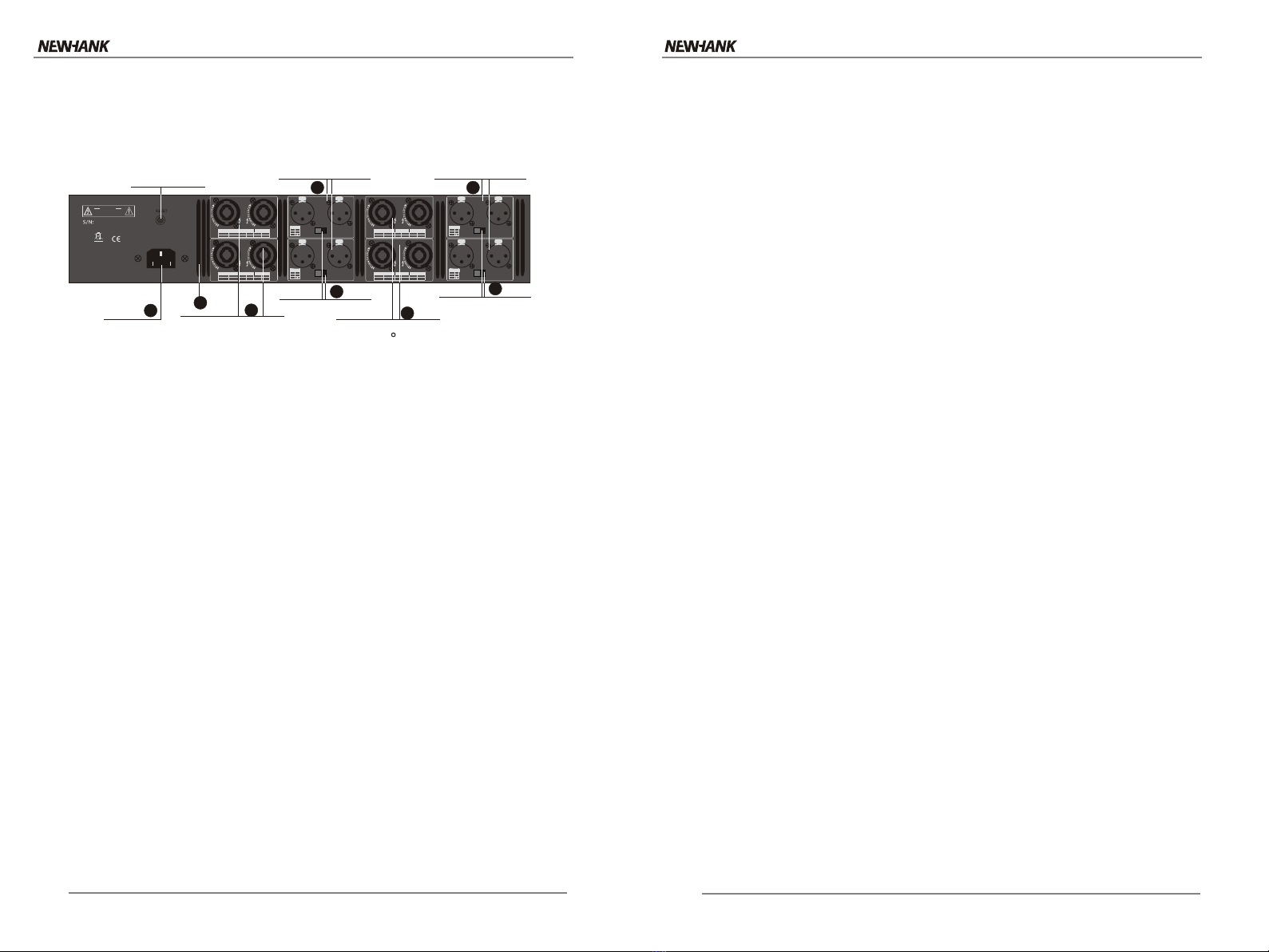
Bridge-Mono Wiring Using the Speakon Connectors
Bridge-mono mode doubles the output power of the amplifer.
1. See thefollowing figure. Onthe back panel,set the Output Mode switch toBRIDGE.
2. Wire the speaker to the speakon connector as shown.
3. Only theChannel 1 Gain Control works inBridge-mono mode.
Bridge Wiring D4000
2-
2+
1-
1+
+
-
Page 10
+
-
+
-
CH1CH2 CH2 CH1
220-240V~50/60Hz
CH3CH4
OUTPUTS 3&4
1+
2+ 1-
POS NEG
INPUTS 3&4
BRIDGE MONO
STEREO
P2
P3
P1
1+ 1-
POS NEG POS NEG
CH4 CH3
+
-
1+
BRIDGE CH1 CH2 CH1
XLR
WARNING - TO REDUCETHE
RISK OF FIREOR ELECTRICAL SHOCK.
TO RAIN ORMOISTURE
AVIS-RISQUE DE CHOC
ELECTRIOUE-NE PAS OUVRIR.
AVERTISSEMENT- ENERGIE
ELECTRIOUE DANGEREUSE`VOIRLE
CAHIERD`INSTRUCTIONS
CAUTION
RISK OF ELECTRIC SHOCK
DO NOT OPEN
INPUTS 1&2
BRIDGE MONO
STEREO
P2
P3
P1
CH2 CH1
+
-
XLR
CH1CH2
OUTPUTS 1&2
1+
2+ 1-
POS NEG
1+ 1-
POS NEG POS NEG
1+
BRIDGE CH1 CH2 CH1
INPUTS 7&8
BRIDGE MONO
STEREO
P2
P3
P1
CH8 CH7
+
-
XLR
INPUTS 5&6
BRIDGE MONO
STEREO
P2
P3
P1
CH6 CH5
+
-
XLR
CH71CH8
1+
2+ 1-
POS NEG
1+ 1-
POS NEG POS NEG
1+
BRIDGE CH1 CH2 CH1
OUTPUTS 5&6
1+
2+ 1-
POS NEG
1+ 1-
POS NEG POS NEG
1+
BRIDGE CH1 CH2 CH1
BRIDGE MONO
STEREO
+
-
+
-
OUTPUTS 7&8
BRIDGE MONO
STEREO
BRIDGE MONO
STEREO
BRIDGE MONO
STEREO
2+
3-
1
www.newhank.com www.newhank.com
D series PowerAmplifiers D series PowerAmplifiers
R

Rear Panel Introduction
1. Input connection
It is abalanced 3 core XLR female socket.
2. Status selectionswitch
Push the switch to the position wanted. It is MONOmode at the left, STEREO in the
middle and BRIDGEat the right.
A ) STEREO mode
STEREO is themost commonly used mode. Each channel will keep independent
when it isat stereo mode. The volume control in frontpanel will work for relevant
channel.
B) MONO mode
It is onlythe signal from CH 1 will be used underthe MONO mode. The signals from
all the outputends are the same and the volume control knobswill control the
volume from relevantchannels.
C) BRIDGE mode
It is onlythe signal from CH 1 will be used underthis mode. The signals from the
output ends willbe the same and the phase will be contrast. All the output of the
amplifier will begathered to a output end. Since the amplifier is used asa mono
equipment under theBRIDGE mode, the volume will be controlled byknob CH 1.
The knob atCH 2 does not work at this mode.
Please note, any end ofthe output cord can not be grounded under the BRIDGE
mode because twoends of the cord are output. It is allowed the minimum
impedance to betwice of the one under the normal stereo or mono mode.
3. Cool AirVent
It is thevent for cool air to flow into the amplifier. Pls do not block itwith any stuff or
place any thingin the front of the vent when the amplifieris at working status.
4. Alternating Inputsocket
To be connected with suitablealternating electric power via the powercord.
Protection Functions
Digital power amplifier D series have full protection function against
short circuit, direction current, over-load, over-heat and lower voltage.
The protection will help to prevent possible damage to the equipment
under the extreme situation.
1. Protection against short circuit
The protection circuit of the amplifier will monitor the current output
situation at any time in operation. When short circuit happens or
when the amplifier connects to the load with lower impedance, this
protection function will start to work. The output of the amplifier will
close and the protection circuit will detect the situation every few
seconds automatically. When the short circuit or over-current
disappear, the amplifier will resume to normal work situation.
The protection to very channel will work independently. When the
amplifier is under STEREO mode or MONO mode, if short circuit
happens at any one of the channels, this channel will be in
protected situation, but the other channels will still work normally.
When the amplifier is under BRIDGE mode, every two channels
of the amplifier will be connected to be one channel. So only one
channel of two channel will be found output short circuit (including
grounded short circuit) or over-current. Two channel will be in short-
circuit protection status.
NOTE :
This amplifier is with full short-circuit protection. But long lasting
short-circuit should beavoided by effort because long time
short-circuit may causeover-heat to inside components of the
amplifier and affect the using life of the amplifier.
2. Protection against direction current and secondary audio
When the amplifier is detected to find direct voltage or large range
of secondary audio( lower than 20Hz) signals at the output end, the
amplifier will be in the protection status. It will prevent damage
to the speaker systems. At the same time, the STATUS indicator in
front of the panel will turn from green to orange.
Page 7 Page4
CH1CH2 CH2 CH1
220-240V~50/60Hz
CH3CH4
OUTPUTS 3&4
1+
2+ 1-
POS NEG
INPUTS 3&4
BRIDGE MONO
STEREO
P2
P3
P1
1+ 1-
POS NEG POS NEG
CH4 CH3
+
-
1+
BRIDGE CH1 CH2 CH1
XLR
WARNING - TO REDUCE THE
RISK OF FIRE OR ELECTRICAL SHOCK.
TO RAIN OR MOISTURE
AVIS-RISQUE DE CHOC
ELECTRIOUE-NE PAS OUVRIR.
AVERTISSEMENT- ENERGIE
ELECTRIOUE DANGEREUSE`VOIRLE
CAHIERD`INSTRUCTIONS
CAUTION
RISK OF ELECTRIC SHOCK
DO NOT OPEN
INPUTS 1&2
BRIDGE MONO
STEREO
P2
P3
P1
CH2 CH1
+
-
XLR
CH1CH2
OUTPUTS 1&2
1+
2+ 1-
POS NEG
1+ 1-
POS NEG POS NEG
1+
BRIDGE CH1 CH2 CH1
INPUTS 7&8
BRIDGE MONO
STEREO
P2
P3
P1
CH8 CH7
+
-
XLR
INPUTS 5&6
BRIDGE MONO
STEREO
P2
P3
P1
CH6 CH5
+
-
XLR
CH71CH8
1+
2+ 1-
POS NEG
1+ 1-
POS NEG POS NEG
1+
BRIDGE CH1 CH2 CH1
OUTPUTS 5&6
1+
2+ 1-
POS NEG
1+ 1-
POS NEG POS NEG
1+
BRIDGE CH1 CH2 CH1
OUTPUTS 7&8
Circuit breaker
Provides overload
protection.
Output Connectors
One Speakon and one
Binding Post per channel
connect to loudspeakers.
5Mode switch
stereo(dual),p arallel or bridge.
2
Output Connectors
One Speakon and one
Binding Post per channel
connect to loudspeakers.
R
5
Ac power
Connector 4Mode switch
stereo(dual),p arallel or bridge.
2
Input connectors
One balanced XLR and one
unbalanced RCA per channel.
1
Input connectors
One balanced XLR and one
unbalanced RCA per channel.
1
3
www.newhank.com www.newhank.com
D series PowerAmplifiers D series PowerAmplifiers

Content Index
1. Manual Cover-------------------------------------- cover page
2.Content Index -------------------------------------- page 1
3. Important Safety Instructions-------------------- page 2
4. Product Features ---------------------------------- page 3
5. Protection Features of D Series ----------------- page 4-5
6. Front Panel Introduction ------------------------- page 6
7. Rear Panel Introduction ------------------------- page 7
8. Wiring Instructions --------------------------------- page 8-9
9. Specifications of D Series ------------------------ page10
Page 1 Page 10
Specifications
Guaranteed Minimum Power
1KHz(EIA) with 0.5 THD
4 STEREO (per channel)
8 STEREO (per channel)
8 bridge mono
Performance
Frequency Response (at 1 Watt)
Total harmonic Distortion (THD)
Voltage Gain
Damping Factor
S/N Ratio (20Hz-20Khz,4 Ohms)
Crosstalk
Input sensitivity
Input impedance(nominal)
Balanced
Unbalanced
Connectors,Controls and Indicators
Input Connectors
Output connectors
Front Panel Controls
Rear Panel Controls
LED Indicators
Protection
Ventilation
Dimensions (WxHxD)
Net Weight
Shipping Weight
Construction
Flow-through ventilation from front to back
Three LED lights for every channel. Clip/-10dB,
signal and Mono/bridge/Status lights in front panel.
Output mode switch for mono, stereo or bridge selection
Power on/off switch and Volume Control
SPEAKON
XLR socket ( female)
10K ohms
20K ohms
0.775V
100dB
300 (8 ),10Hz-400Hz
220-240V~50/60Hz
Class D
0.2%
20Hz-20KHz,+0/-1dB
Power voltage
Protection against shortcircuit, directoutput current,
over load, lowvoltage and over-heat
Power Connector Standard IEC connector
Output Grade (Technology Type)
Cooling system Cooling fans with variable speed
483x88x357mm
12.6kg
15.3kg
Channel 8 channel
Accessories Operation manual 1pc,power cord plug 1pc
40dB
-65dB
8x300W
8x500W
4x1000W
D4000D4000
www.newhank.com www.newhank.com
D series PowerAmplifiersD series PowerAmplifiers
Power Consumption 2700W

Page 3 Page 8
PRODUCT FEATURES
Unique and elegant enclosure and front panel design.
Carefully selected high quality components.
Compact structure with only 1 unit height.
Very light weight. Easy to move and install.
Class D toplogy integrated with switch power supply design.
Powerful output and high efficiency
Low electricity consumption
Accurate gain control, switch on/off, signal, clipping and
protection LED light in front panel
Fully automatic protection circuit at every channel, including
protection against direct current , over-heat, over-load
and amplitude limit.
Nice and high efficient cooling system.
XLR balance input and professional SPEAKON output
Momo, Stereo or bridge mode selection pull switch is set on
back panel.
D series are the Class-D digital power amplifiers that are
entirely designed by the manufacturer specially for up-rising
demand to thin and light amplifier from the users. D series will
bring you both satisfied sound effect and long-lasting
performance.
The main features are as the following:
Stereo (Dual) Wiring D4000
1. See thefollowing figure. On the back panel, set the Output Mode Switch to STEREO.
2. Wire thespeakers to the Speakon connectors as shown.
2+
3-
1
2-
2+
1-
1+
+
-
+
-
+
-
+
-
+
-
CH1CH2 CH2 CH1
220-240V~50/60Hz
CH3CH4
OUTPUTS 3&4
1+
2+ 1-
POS NEG
INPUTS 3&4
BRIDGE MONO
STEREO
P2
P3
P1
1+ 1-
POS NEG POS NEG
CH4 CH3
+
-
1+
BRIDGE CH1 CH2 CH1
XLR
WARNING - TO REDUCETHE
RISK OF FIREOR ELECTRICAL SHOCK.
TO RAIN ORMOISTURE
AVIS-RISQUE DE CHOC
ELECTRIOUE-NE PAS OUVRIR.
AVERTISSEMENT- ENERGIE
ELECTRIOUE DANGEREUSE`VOIRLE
CAHIERD`INSTRUCTIONS
CAUTION
RISK OF ELECTRIC SHOCK
DO NOT OPEN
INPUTS 1&2
BRIDGE MONO
STEREO
P2
P3
P1
CH2 CH1
+
-
XLR
CH1CH2
OUTPUTS 1&2
1+
2+ 1-
POS NEG
1+ 1-
POS NEG POS NEG
1+
BRIDGE CH1 CH2 CH1
INPUTS 7&8
BRIDGE MONO
STEREO
P2
P3
P1
CH8 CH7
+
-
XLR
INPUTS 5&6
BRIDGE MONO
STEREO
P2
P3
P1
CH6 CH5
+
-
XLR
CH71CH8
1+
2+ 1-
POS NEG
1+ 1-
POS NEG POS NEG
1+
BRIDGE CH1 CH2 CH1
OUTPUTS 5&6
1+
2+ 1-
POS NEG
1+ 1-
POS NEG POS NEG
1+
BRIDGE CH1 CH2 CH1
BRIDGE MONO
STEREO
+
-
+
-
+
-
+
-
OUTPUTS 7&8
BRIDGE MONO
STEREO
BRIDGE MONO
STEREO
BRIDGE MONO
STEREO
Parallel Wiring Using the Speakon Connectors
with this wiring, a signal sent to one of the inputconnectors is paralleled to both
channels so thatit is reproduced by both speakers.
1. See thefollowing figure. On the back panel, set the Output Mode Switch to MONO.
2. Wire thespeakers to the Speakon connectors as shown.
R
R
Mono Wiring D4000
+
-
+
-
+
-
+
-
CH1CH2 CH2 CH1
220-240V~50/60Hz
CH3CH4
OUTPUTS 3&4
1+
2+ 1-
POS NEG
INPUTS 3&4
BRIDGE MONO
STEREO
P2
P3
P1
1+ 1-
POS NEG POS NEG
CH4 CH3
+
-
1+
BRIDGE CH1 CH2 CH1
XLR
WARNING - TO REDUCETHE
RISK OF FIREOR ELECTRICAL SHOCK.
TO RAIN ORMOISTURE
AVIS-RISQUE DE CHOC
ELECTRIOUE-NE PAS OUVRIR.
AVERTISSEMENT- ENERGIE
ELECTRIOUE DANGEREUSE`VOIRLE
CAHIERD`INSTRUCTIONS
CAUTION
RISK OF ELECTRIC SHOCK
DO NOT OPEN
INPUTS 1&2
BRIDGE MONO
STEREO
P2
P3
P1
CH2 CH1
+
-
XLR
CH1CH2
OUTPUTS 1&2
1+
2+ 1-
POS NEG
1+ 1-
POS NEG POS NEG
1+
BRIDGE CH1 CH2 CH1
INPUTS 7&8
BRIDGE MONO
STEREO
P2
P3
P1
CH8 CH7
+
-
XLR
INPUTS 5&6
BRIDGE MONO
STEREO
P2
P3
P1
CH6 CH5
+
-
XLR
CH71CH8
1+
2+ 1-
POS NEG
1+ 1-
POS NEG POS NEG
1+
BRIDGE CH1 CH2 CH1
OUTPUTS 5&6
1+
2+ 1-
POS NEG
1+ 1-
POS NEG POS NEG
1+
BRIDGE CH1 CH2 CH1
BRIDGE MONO
STEREO
+
-
+
-
+
-
+
-
OUTPUTS 7&8
BRIDGE MONO
STEREO
BRIDGE MONO
STEREO
BRIDGE MONO
STEREO
www.newhank.com www.newhank.com
D series PowerAmplifiers D series PowerAmplifiers

Front Panel Introduction
1. Power On/Off Switch
PLS push downON to turn on the powerof the amplifier, push down OFF to turn off.
2. Air Vent
It is thevent for the heated air toflow through from inside of theamplifier. Pls do not
put any stuffinside or in the front ofthe vent to block the airflow.
LED Indicators
The user canknow the working status of every channelwith these LED indication lights.
The LED lightsincludes three kinds of indicator asthe following:
3. Working mode indicators MONO and BRIDGE
When the modeselection switch in the rear panelis turned to BRIDGE or MONO,
the relevant LEDlight in front panel will belighten up at the same time. When it is at
default working modeSTEREO, these indicator lights will not shine.
4. Signal indicators SIGNAL , CLIP and -10dB
Even very small outputcan make SIGNAL to lighten up, it shows relevant channel is
at work. When the light -10dB lightens up, it shows the output levelis -10dB under
the rated value. When CLIP lightens up, it shows theoutput level is higher
than the ratedvalue and the amplifier is at protection status.
5. VolumeControl
The VolumeControl knob is used to adjust the volume. When it isturned at
clockwise direction, the volume will be increased. Wen it is turned at
anti-clockwise direction, the volume will be decrease.
As to the2 channel amplifier, when itis at STEREO mode or MONOmode, turn
the volume controlknobs at CH 1 and CH 2 to reach the wanted volumelevel.
But when itis at BRIDGE mode, turn only the knobsat Ch1 to get the volume
wanted. The knob at CH 2 does not work under BRIDGEmode.
3. Starting delay and mute
There is a soft start procedure inside the amplifier after turn the
power switch to ON position. During this time, the amplifier will
be in protection status. The STATUS light will turn to orange color.
The amplifier will turn to normal work status after about 4 seconds
and the STATUS light will turn from orange to green. All the other
indicator lights will lighten up to show the live mode.
When turn the power switch to OFF position, the amplifier will be
in shut off status. The light STATUS will turn from green to orange
and turn off finally.
4. Protection against over-heat
When the temperature of the main cooling system of the
amplifier is under 50 centi-degree, the cooling fan will run at
very low speed. When it is between 50 and 70 centidegree,the
cooling fan will run from slow speed via stepless speed change
to full speed. When the temperature of the main cooling system
reaches 90 centi-degree, the STATUS light will start to flash green
and orange alternatively, which warns the user high temperature
of the cooling system and to lower down the output intensity. .
NOTE
When the protection status happens at starting of the
amplifier, it shows there maybe serious damage
inside the amplifier. Pls shut off the power and take
off the power cord . Then send the amplifier to the
professional expert for maintenance.
Page 5 Page 6
-inf 0-inf 0-inf 0-inf 0-inf 0-inf 0-inf 0-inf 0
ON/ OFF
POWER
Rack-Mount Hole
(one of four)
SIGNAL/ CLIP led
RED LED,one per
channel,ashes when
signal is audibly distorting
4
Gain control
Sets output level of
each channel.
5
Grill
Allows ow-through
ventilation from front to back.
2
Power switch
Push-on,push-off.
1
3
D4000D4000
www.newhank.com www.newhank.com
D series PowerAmplifiersD series PowerAmplifiers
Other Newhank Power Amplifier manuals