Newhank PRO4600 User manual

Specifications
1KHz(EIA) with 0.5Ј THD
2ohms STEREO 2600Wx2
Performance
Total harmonic Distortion (THD)
Damping Factor
S/N Ratio (20Hz-20Khz,4 Ohms)
Crosstalk Ј1KHz, 4ohm)
Input sensitivity
Input impedance(nominal)
Connectors,Controls and Indicators
Input Connectors
Output connectors
Front Panel Controls
Rear Panel Controls
LED Indicators
Protections
Ventilation
Dimensions (WxHxD)
Net Weight
Shipping Weight
Construction
Flow-through ventilation from front to back
Three LED lights for every channel. Clip/-10dB,
signal and Mono/bridge/Status lights in front panel.
Output mode switch for mono, stereo or bridge selection
Power on/off switch and Volume Control
SPEAKON
XLR socket ( female)
Balance 10K ohms, unbalanced 20K ohms
0.775V,0dB
>106dB
>600 (10Hz-400Hz, 8 ohm)
~90-265V
Class D
<0.05%(@ 8ohms, 1KHz, 1/6 rated power
10Hz-20KHz,+/-1dB
Page 11
Power voltage
Protection against RF, on/off switching, short circuit,
direct current, over load, low voltage &over-heat
Power Connector Standard IEC connector
Output Grade (Technology Type)
Cooling system
Cooling fans with variable speed
6.60kg
7.50kg
8ohms bridge mono 4600W
Accessories Operation manual 1pc,power cord plug 1pc
>40dB
4ohms STEREO 2300Wx2
8ohms STEREO 1400Wx2
Frequency Response (at 1 Watt)
Voltage Gain 42.7/40.5/32
Inter-modulation Distortion (IMD) <0.15%(@ 8ohms, 1KHz, 1/8 rated power
483x44x230mm
Power Delay 4 seconds
Slew Rate
>20v/ S
0dB 0 dB
-Ў
PROT ECT
CLIP
-3dB
-6dB
-12d B
-24d B
SIGN AL
ON
PROT ECT
CLIP
-3dB
-6dB
-12dB
-24dB
SIGN AL
ON
CH A CH B
DIG ITAL PROF ESSIO NAL POWE R AMPLIF IER
-Ў
PRO4600 Manual
Guaranteed Minimum Power PRO4600
www.newhank.com
PRO4600 Power Amplifier

Page 9
2+
3-
1
2-
2+
1-
1+
2+
2-
1-
1+
+
-
+
-
+
-
+
-
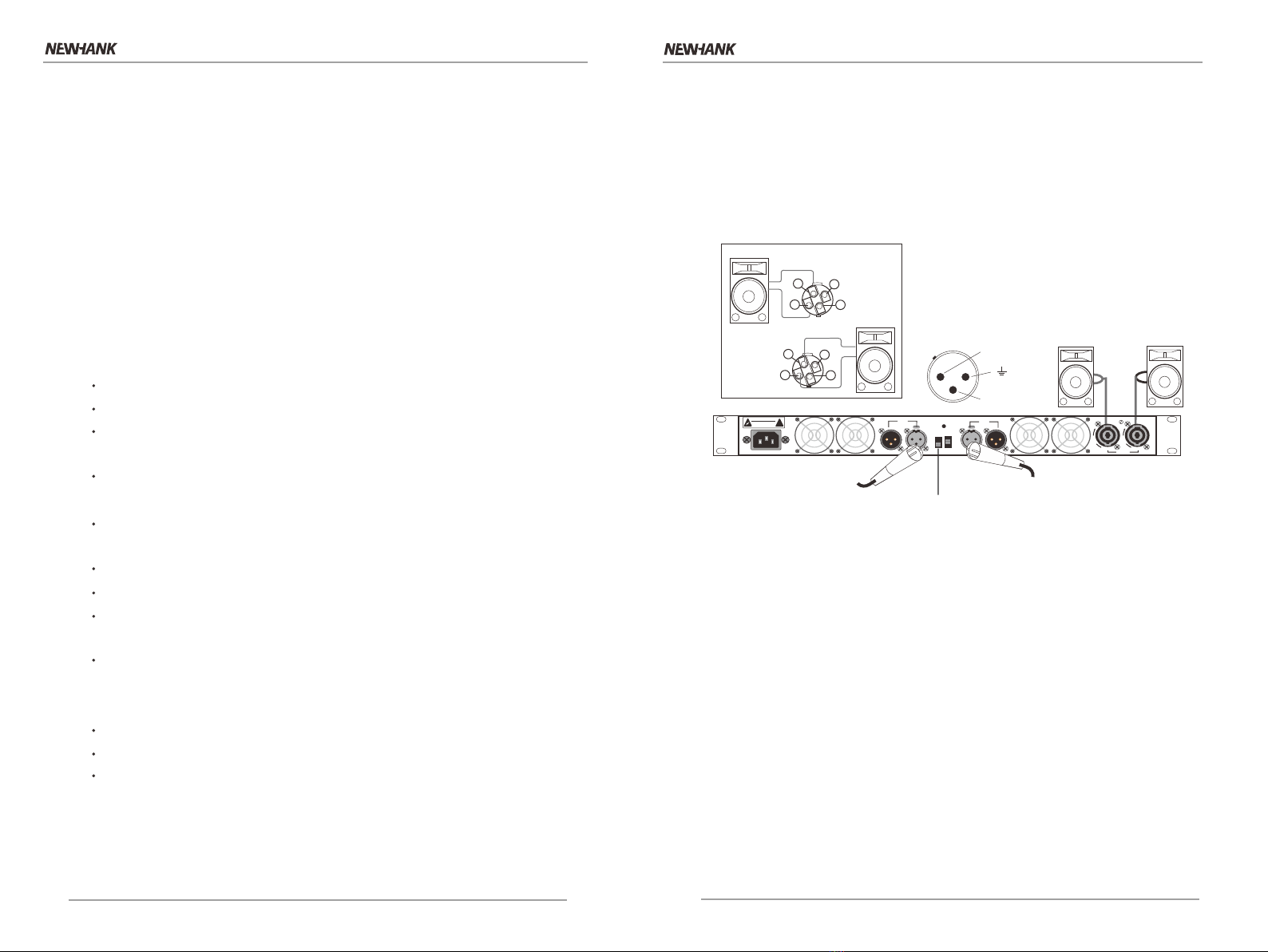
Parallel Wiring Using the Speakon Connectors
with this wiring, a signal sent to one of the input connectors is parallelled to both
channels so that it is reproduced by both speakers.
1. See the following. On the back panel, set the Output Mode Switch to MONO.
2. Wire the speakers to the Speakon connectors as shown.
R
Mono/Parallel Wiring
BRG
PAR
ST
Mode selection Switch
Move the switch to PAR position
CAU TION :
DO NOT O PEN
!
RISK O F ELECT RIC SHO CK
PUSH PU SH
90V~260 V/50-60 Hz LI NK INP UT
BRG
PAR
ST
0.77 5V
1.0V
32dB
INP UT LI NK
CHA
CHA CHB
CHA= AЎ CHB= 1Ў
BRG= CHA+, 2-
BRG= 2¦
CHB 2Ў=N/A
OUT PUTS
L
O
C
K
L
O
C
K
CAUTION
RISK O F ELECTRIC SHOCK
DO NOT OPEN
!
Important Safety Instructions
1. Read these instructions.
2. Keep these instructions.
3. Heed all warnings.
4. Follow all instructions.
5. Do not use this apparatus near water.
6. Clean only with a dry cloth.
7. Do not block any ventilation opening. Install in accordance with the
manufacturer`s instructions.
8. Do not install near any heat source such as radiator ,heat register,
stove, or other apparatus(including amplifier )that produce heat.
9. Do not defeat the safety purpose of the polarized or grounding-type
plug. A polarized plug has two blades with one wider than the other.
A grounding-type plug has two blades and a third grounding prong.
The wide blade or the third prong is provided for your safety. If the
provided plug does not ft into your socket ,consult an electrician for
replacement of the correct socket.
10.Protect the power cord from being walled on pinched, particularly
at the plug, convenience receptacle ,and the point where they exit
from the apparatus.
11.Only use attachments/accessories specified by the manufacturer.
12.Use only with a cart, stand, tripod, bracket, or table
specified by the manufacturer, or sold with the apparatus.
When a cart is used, use caution when moving the cart/
apparatus combination to avoid injury from tip-over.
13.Unplug this apparatus during lightning storms or when unused for
long periods of time.
14.Refer all servicing to qualifed service personnel. Servicing is required
when the apparatus has been damaged in any way, such as power-
supply cord or plug is damaged ,liquid has been spilled or objects
have fallen into the apparatus, the apparatus has been exposed to rain
or moisture, does not operate normally, or has been dropped.
15.Use the mains plug to disconnect the apparatus from the mains.
16.WARNING: TO REDUCE THE RISK OF FIRE OR ELECTRIC SHOCK, DO
NOT EXPOSE THIS APPARATUS TO RAIN OR MOISTURE.
17.WARING:THIS APPLIANCE SHALL BE CONNECTED TO A MAINS
SOCKET OUTLET WITH A PROTECTIVE EARTHING CONNECTION.
18.DO NOT EXPOSE THIS EQUIPMENT TO DRPPING OR
SPLASHING AND ENSURE THAT NO OBJECTS FILLED
WITH LIQUIDS,SUCH AS VASES, ARE PLACED ON THE
EQUIPMENT.
19.THE MAINS PLUG OF THE POWER SUPPLY CORD SHALL REMAIN
READILY OPERABLE.
TO PREVENT ELECTRIC SHOCK DO NOT REMOVE TOP
OR BOTTOM COVERS. NO USER SERVICEABLE PARTS
INSIDE. REFER SERVICING TO QUALIFIED SERVICE
PERSONNEL.
TO COMPLETELY DISCONNECT THIS EQUIPMENT
FROM THE AC MAINS, DISCONNECT THE POWER
SUPPLY CORD PLUG FROM THE AC RECEPTACLE. THE
MAINS PLUG OF THE POWER SUPPLY CORD SHALL
REMAIN READILY OPERABLE.
WARNING: PAY ATTENTION TO A PROCEDURE,PRACTICE, CONDI-
TION OR THE LIKE,IF NOT CORRECTLY PERFORMED OR ADHERED
TO, COULD RESULT IN PERSONAL INJURY OR DEATH.
CAUTION! Do not locate sensitive high-
gain equipment such as preamplifiers or
tape decks directly above or belo-w the unit.
be cause this amplifier has a high power
density, it has a strong magnetic field which
can induce hum into unshielded devices that
are located nearby. the field is strongest just
above and below the unit.
If an equipment rack is used, we recommend
locating the amplifier(s) in the bottom of the
rack and the rack and the preamplifieror other
sensitive equipment at the top.
MAGNETIC FIELD
IMPORTANT
XLi series amplifers require class 2 output wiring.
The device is designed and evaluated under the condi
tion of non-tropical climate;and,it can be only used
in locations in non-tropical climate areas. Using the
device in tropical climate areas would result in high
safety risk.
This device is designed and evaluated under the con
dition of 2000 meters tall above sea lever;and,it can
be only used in locations below 2000 meters tall above
sea level. Using the device above 2000 meters altitude
would result in high safety risk.
The exclamation point triangle is used to alert the
user to important operating or maintenance instruc
tions.
The lightning bolt triangle is used to alert the user to
the risk of electric shock.
WATCH FOR THESE SYMBOLS:
CAUTION: PAY ATTENTION TO PROCEDURE,PRACTICE,
CONDITION OR THE LIKE,IF NOT CORRECTLY PERFORMED OR
ADHERED TO, COULD RESULT IN DAMAGE OR DESTRUCTION TO
PART OR ALL OF THE COMPONENT.
2000m
SSS
Page 2
www.newhank.com
www.newhank.com
PRO4600 Power Amplifier PRO4600 Power Amplifier

Rear Panel Introduction
1. Input connectors
It is balanced 3 core XLR female sockets.
2. Mode selection switch
Push the switch to the position wanted. It is MONO mode at the middle,
STEREO in the under and BRIDGE at the upper.
A ) STEREO mode
STEREO is the most commonly used mode. Each channel will keep
independent when it is at stereo mode. The volume control in front panel
will work for relevant channel.
B) MONO mode
It is only the signal from CH 1 will be used under the MONO mode. The
signals from all the output ends are the same and the volume control knobs
will control the volume from relevant channels.
C) BRIDGE mode
It is only the signal from CH 1 will be used under this mode. The signals from
the output ends will be the same and the phase will be contrast. All the output
of the amplifier will be gathered to a output end. Since the amplifier is used as
a mono equipment under the BRIDGE mode, the volume will be controlled by
knob CH 1. The knob at CH 2 does not work at this mode.
Please note, any end of the output cord can not be grounded under BRIDGE
mode because two ends of the cord are output. It is allowed the minimum
impedance to be twice of the one under the normal stereo or mono mode.
3. Cooling Air Vent
It is the vent for cool air to flow into amplifier. Pls do not block with any stuff
or place any thing in the front of the vent when the amplifier is at working.
4. Alternating Power Input socket (AC Power Connector)
To be connected with suitable alternating electric power via the power cord.
Mode Selection Switch
Stereo(dual),p arallel or bridge.
Output Connectors
One Speakon and one
Binding Post per channel
connected to loudspeakers.
R
Input connectors
One balanced XLR and one
unbalanced RCA per channel.
Ac power
Connector
Protection Functions
Digital power amplifier of PRO4600 have full protection function
against short circuit, direction current, over-load, over-heat and
lower voltage. The protection will help to prevent possible damage
to the equipment under the extreme situation.
1. Protection against short circuit
The protection circuit of the amplifier will monitor the current output
situation at any time in operation. When short circuit happens or
when the amplifier connects to the load with lower impedance, this
protection function will start to work. The output of the amplifier will
close and the protection circuit will detect the situation every few
seconds automatically. When the short circuit or over-current
disappear, the amplifier will resume to normal work situation.
The protection to very channel will work independently. When the
amplifier is under STEREO mode or MONO mode, if short circuit
happens at any one of the channels, this channel will be in
protected situation, but the other channels will still work normally.
When the amplifier is under BRIDGE mode, every two channels
of the amplifier will be connected to be one channel. So only one
channel of two channel will be found output short circuit (including
grounded short circuit) or over-current. Two channel will be in short-
circuit protection status.
NOTE :
This amplifier is with full short-circuit protection. But long lasting
short-circuit should be avoided by effort because long time
short-circuit may cause over-heat to inside components of the
amplifier and affect the using life of the amplifier.
2. Protection against direction current and secondary audio
When the amplifier is detected to find direct voltage or large range
of secondary audio( lower than 20Hz) signals at the output end, the
amplifier will be in the protection status. It will prevent damage
to the speaker systems. At the same time, the STATUS indicator in
front of the panel will turn from green to orange.
Page 7 Page4
4
2
1
5
CHA
3
3
Cooling Air Vent
Cooling Air Vent
5.Output Connectors
Each channel to be connected with suitable Speakon connector then
connectted to loudspeakers..
CAU TION:
DO NOT O PEN
!
RISK OF E LECTR IC SHOC K
PUSH PU SH
90V~2 60V/5 0-60H z LIN K INP UT
BRG
PAR
ST
0.77 5V
1.0V
32dB
INP UT LIN K
CHA
CHA CHB
CHA= AЎ CHB= 1Ў
BRG= CHA+, 2-
BRG= 2¦
CHB 2Ў= N/A
OUT PUTS
L
O
C
K
L
O
C
K
www.newhank.com
www.newhank.com
PRO4600 Power Amplifier PRO4600 Power Amplifier

Bridge-Mono Wiring Using the Speakon Connectors
Bridge-mono mode doubles the output power of the amplifer.
1. See the following. On the back panel, set the Output Mode
switch to BRIDGE.
2. Wire the speaker to the speakon connector as shown.
3. Only the Channel 1 Gain Control works in Bridge-mono mode.
2+
3-
1
2-
2+
1-
1+ +
-
+
-
R
Content Index
1. Manual Cover-------------------------------------- cover page
2.Content Index -------------------------------------- page 1
3. Important Safety Instructions------------------- page 2
4. Product Features -------------------------------- page 3
5. Protection Features ------------------------------ page 4-5
6. Front Panel Introduction ------------------------- page 6
7. Rear Panel Introduction ------------------------- page 7
8. Wiring Instructions -------------------------------- page 8-10
9. Specifications -------------- ----------------------- page11
Page 1 Page 10
Bridge Wiring
Mode Selection Switch
Move the switch to BRG position
CAU TION:
DO NOT O PEN
!
RISK OF E LECTR IC SHOC K
PUSH PU SH
90V~2 60V/5 0-60H z LIN K INP UT
BRG
PAR
ST
0.77 5V
1.0V
32dB
INP UT LIN K
CHA
CHA CHB
CHA= AЎ CHB= 1Ў
BRG= CHA+, 2-
BRG= 2¦
CHB 2Ў=N/A
OUT PUTS
L
O
C
K
L
O
C
K
www.newhank.com
www.newhank.com
PRO4600 Power Amplifier PRO4600 Power Amplifier

Page 3 Page 8
2+
3-
1+
-
+
-
+
-
+2-
2+
1-
1+
-
PRODUCT FEATURES
Unique and elegant enclosure and front panel design.
Carefully selected high quality components.
PFC built-in, enable the products workable at wide voltage
range ~90-265V.
Compact structure with only 1 unit height and 9" depth and
light weight, easy to move and install.
Soft resonant switching power supply LLC module and fixed
switch frequency Class-D PCB module...
Powerful output and high efficiency
Low electricity consumption
Accurate gain control, switch on/off, signal, clipping and
protection LED light in front panel
Fully automatic protection circuit at every channel, including
protection against direct current , over-heat, over-load and
amplitude limit.
Nice and high efficient cooling system.
XLR balance input and professional SPEAKON output
Momo, Stereo or bridge mode selection pull switch is set on
back panel.
PRO4600 is the Class-D digital power amplifier that is entirely
designed by the manufacturer specially for up-rising demand
to wider voltage range, stable 2 ohm,thin and light amplifier
from the users. PRO4600 will bring you both satisfied sound
effect and long-lasting performance.
The main features are as the following:
Stereo(Dual) Wiring
1. See the following figure. On the back panel, set the Output Mode
Switch to STEREO.
2. Wire the speakers to the Speakon connectors as shown.
2-
2+
1-
1+
Mode Selection Switch
Move the switch to ST position
CAU TION:
DO NOT O PEN
!
RISK OF E LECTR IC SHOC K
PUSH PU SH
90V~2 60V/5 0-60H z LIN K INP UT
BRG
PAR
ST
0.77 5V
1.0V
32dB
INP UT LIN K
CHA
CHA CHB
CHA= AЎ CHB= 1Ў
BRG= CHA+, 2-
BRG= 2¦
CHB 2Ў= N/A
OUT PUTS
L
O
C
K
L
O
C
K
www.newhank.com
www.newhank.com
PRO4600 Power Amplifier PRO4600 Power Amplifier

Front Panel Introduction
1. Power On/Off Switch
Push ON to turn on the power of the amplifier, push OFF to turn off.
2. Air Vent
It is the vent for the heated air to flow through from inside of the amplifier.
Pls do not put any stuff inside or in the front of the vent to block the air flow.
3.LED Indicators
The user can know the working status of every channel with these LED indication
lights. The LED lights includes three kinds of indicator as the following:
Working mode indicators MONO and BRIDGE
When the mode selection switch in the rear panel is turned to BRIDGE or MONO,
the relevant LED light in front panel will be lighten up at the same time. When
it is at default working mode STEREO, these indicator lights will not shine.
4. Working status indicator STATUS
When the power to the amplifier is turned on, the light ON will be lighten up.
When the amplifier is at normal working status, the LED light ON will be lighten
up in green color. When the amplifier is under protection and mute status, it will
flash in RED color.
5. Signal indicators SIGNAL , CLIP and -10dB
Even very small output can make SIGNAL to lighten up, it shows relevant
channel is at work. When the light -10dB lightens up, it shows the output level
is -10dB under the rated value. When CLIP lightens up, it shows the output level
is higher than the rated value and the amplifier is at protection status.
6. Volume Control
The Volume Control knob is used to adjust the volume. When it is turned at
clockwise direction, the volume will be increased. Wen it is turned at anti-
clockwise direction, the volume will be decrease. As to the 2 channel amplifier,
when it is at STEREO mode or MONO mode, turn the volume control knobs at
CH 1 and CH 2 to reach the wanted volume level. But when it is at BRIDGE
mode, turn only the knobs at Ch1 to get the volume wanted. The knob at CH 2
does not work under BRIDGE mode.
Grill
Allows o w-through
ventil ation from front to back.
Rack-Mount Hole
(one of four)
Gain control
Sets out put level of
each cha nnel.
SIGNAL/ CLIP led
RED LED, one per
channe l,fashes when
signal i s audibly distorting
Power switch(covered by the handle)
Push-o n,push-off.
3. Starting delay and mute
There is a soft start procedure inside the amplifier after turn the
power switch to ON position. During this time, the amplifier will
be in protection status. The STATUS light will turn to orange color.
The amplifier will turn to normal work status after about 4 seconds
and the STATUS light will turn from orange to green. All the other
indicator lights will lighten up to show the live mode.
When turn the power switch to OFF position, the amplifier will be
in shut off status. The light STATUS will turn from green to orange
and turn off finally.
4. Protection against over-heat
When the temperature of the main cooling system of the amplifier is
under 50 centi-degree, the cooling fan will run at very low speed.
When it is between 50 and 70 centidegree,the cooling fan will run
from slow speed via stepless speed change to full speed. When the
temperature of the main cooling system reaches 90 centi-degree, the
STATUS light will start to flash green and orange alternatively, which
warns the user high temperature of the cooling system and to lower
down the output intensity.
NOTE
When the protection status happens at starting of the amplifier,
it shows there maybe serious damage inside the amplifier. Pls shut
off the power and take off the power cord . Then send the amplifier
to the professional expert for maintenance.
Page 5 Page 6
1
6
2
5
43
3
0dB 0 dB
-Ў
PRO TECT
CLI P
-3d B
-6d B
-12dB
-24dB
SIG NAL
ON
PRO TECT
CLI P
-3d B
-6d B
-12dB
-24dB
SIG NAL
ON
CH A CH B
DIG ITAL PROF ESSIO NAL POWE R AM PLIFI ER
-Ў
Grill
Allows o w-through
ventil ation from front to back.
2
www.newhank.com
www.newhank.com
PRO4600 Power Amplifier PRO4600 Power Amplifier
Other Newhank Power Amplifier manuals