HILL PUMPS EC-3000 Operator's manual
EC3000 PORTABLE AIR COMPRESSOR
USER INSTRUCTION MANUAL
Rev 4.03
March 2020
Contents
3
4-5
5-8
9
9
9
9
Parts Included
Set Up
Operating Instructions
Troubleshooting
Closedown
Storage
Maintenance
THIS PRODUCT IS DESIGNED TO FILL PRE-CHARGED PCP AIR GUNS AND PAINTBALL GUNS
DIRECTLY. IT CAN ALSO BE USED TO TOP UP SMALL TANKS, BUDDY BOTTLES, AND CYLINDERS
UP TO 4 LITRES. LARGE CYLINDERS AND TANKS ABOVE 4 LITRES SHOULD ONLY BE FILLED BY
COMPETENT OR QUALIFIED PEOPLE
NOT FOLLOWING THE INSTRUCTIONS OR MISUSE OF THE COMPRESSOR WILL VOID YOUR
WARRANTY AND MAY RESULT IN DEATH OR INJURY
DO NOT EXCEED MAXIMUM FILL PRESSURE OF YOUR CYLINDER AT ROOM TEMPERATURE.
ONLY FILL CYLINDERS THAT ARE IN GOOD CONDITION AND ARE IN DATE OF INSPECTION.
READ ALL INSTRUCTIONS BEFORE USE.
TO PROTECT YOUR EYES YOU SHOULD ALWAYS WEAR
SAFETY GLASSES WHEN OPERATING THIS COMPRESSOR AND
HEARING PROTECTION WHEN BLEEDING
THIS COMPRESSOR PRODUCES CLEAN AIR SUITABLE FOR FILLING PCP AIRGUNS.
IT DOES NOT COMPRESS AIR SUITABLE OR CERTIFIED FOR BREATHING APPARATUS.
DO NOT USE IT TO FILL SCUBA TANKS THAT MAY LATER BE USED FOR BREATHING.
IMPORTANT
DANGER
IMPORTANT
WARNING
DANGER OF EXPLOSION
FROM OVERFILLING OF COMPRESSED AIR CYLINDERS

3
Parts Included
1x EC-3000 Compressor
1x Power Cable
1x High Pressure Filling Hose 1/8” and male Quick Release Coupling
1x Hill H8000 Oil
1x Hill Silicone Oil
4
CAUTION - please read and understand the following instructions before use.
CAUTION - ONCE YOU HAVE CORRECTLY FILLED THE COMPRESSOR
WITH LUBRICANTS, THE COMPRESSOR MUST BE KEPT UPRIGHT AND
LEVEL AT ALL TIMES. ENSURE THE COMPRESSOR IS USED ON A NON-SLIP
FLOOR, PREFERABLE SAT ON ANTI-SLIP MATTING. IF THE COMPRESSOR
IS TO BE MOVED OR TRANSPORTED FOR STORAGE OR MAINTENANCE,
ENSURE ALL LUBRICANTS ARE DRAINED FIRST.
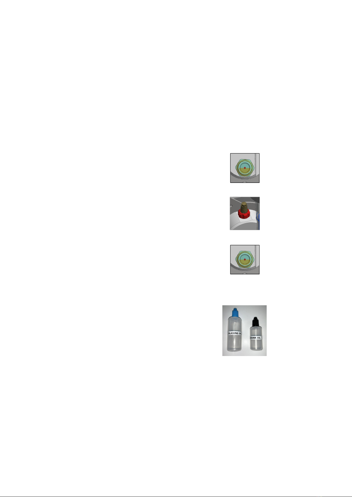
1. Oil Level
With the compressor positioned on a level surface,
check that the oil level meets the
red dot on the sight glass.
Top up as necessary using the following:
Remove rep cap - screw anti-clockwise
Slowly squeeze the Hill H8000 crank oil into the
exposed hole until the lubricant level meets the
red dot in the sight glass
DO NOT MIX CRANK OIL AND SILICONE OIL AND DO NOT OVERFILL
Leave the oil to settle for 5 mins, if the oil level drops
below the red dot apply more oil until the oil level
is maintained
Replace the red cap until finger tight
Set Up
5
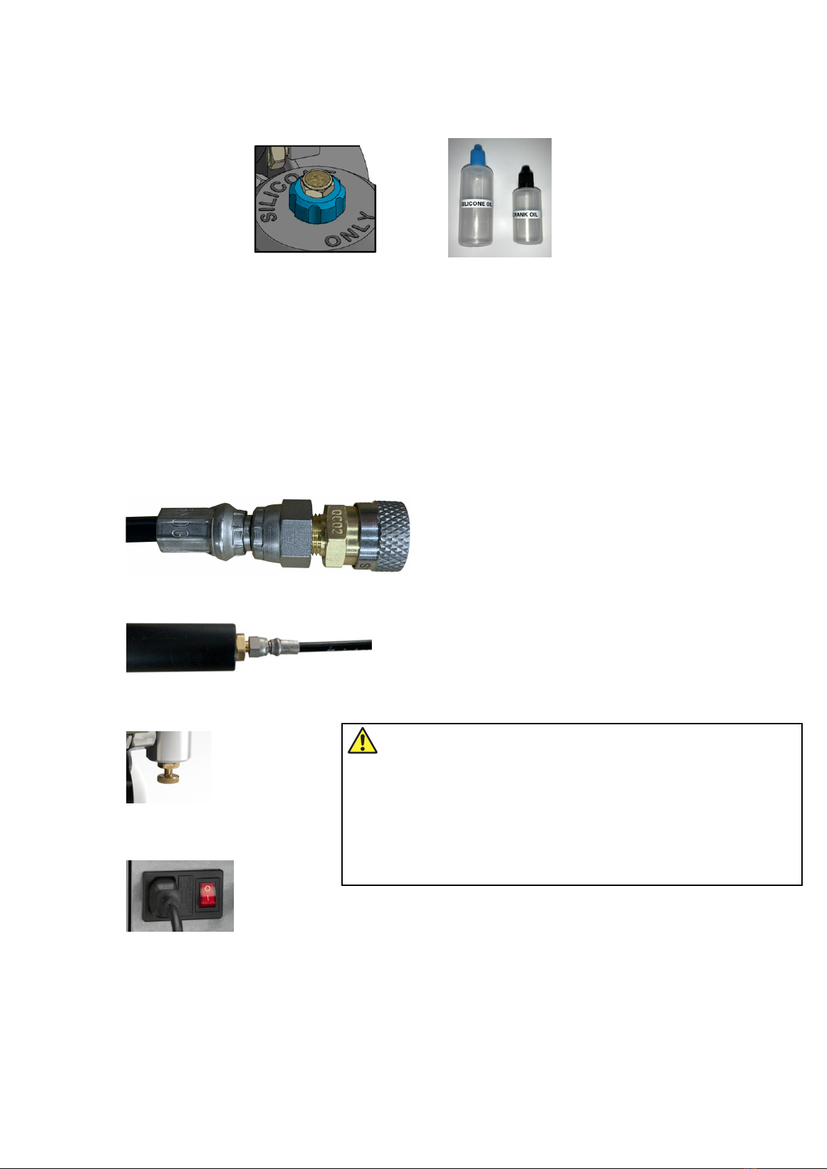
2. Silicone Lubricant Level
3. Power connection and Operating Instructions
Fill the lubricant reservoir up to the blue line using the following:
Remove blue cap - screw anticlockwise
Slowly squeeze the Hill Silicone Oil through the exposed hole until the oil reaches the limit
indicated on the reservoir
DO NOT MIX CRANK OIL AND SILICONE OIL
Replace blue cap until finger tight
Connect filling probe to hose, ensure spanner tight
Connect filling probe to cylinder, ensure spanner tight
Ensure bleed screw is closed (finger tight)
Insert power cable into pump
Please avoid using any electrical extension leads if possible. However, if you are using a 3rd
party extension lead, this must be rated to a minimum of 110v/16A or 230v/13A depending
on your local power supply. If unsure, please determine what your local power supply is
before operating the compressor.
CAUTION: If using a quick release release coupling,
always check and make sure the collar on the female
quick disconnect is inthe forward position and secure
on the male fitting you are connecting it to. It is
recommendedthat you check the connection by attempting
to pull the female and male ends apart while the collar
on the fitting is in the forward position.

6
Switch compressor on
The screen will briefly show the Hill logo, the software version and the accumulated running
hours
before requesting confirmation that the lubricant levels have been checked and are correct
Rotate the knob again to alternate between BAR and PSI. When you have chosen the unit of
measure, depress the control knob to confirm. The chosen unit of measure will be retained for
future use even when the compressor is switched off. This can be chaged at any time.
Press the rotary control knob
to confirm the lube check
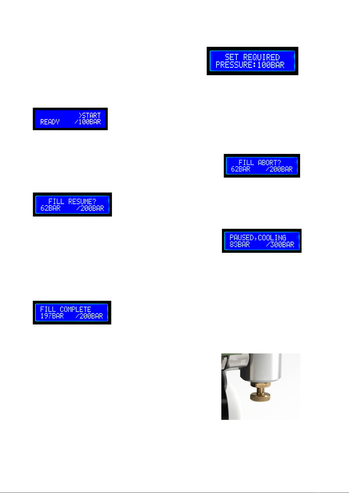
The display will then change to “set pressure”. A default pressure of 100BAR (1450PSI/10MPa)
is diplayed
If you are using the compressor for the first time, the unit of measure will display in BAR.
To change the unit of measure to PSI or MPa, rotate the control knob clockwise and press
to confirm
To return to the “set pressure” screen, rotate the knob anticlockwise and press to confirm
7
To set the pressure, rotate the control knob clockwise to
increase the fill pressure required. When you reach the
desired pressure, press the control knob to confirm.
The maximum pressure that can be set is 300BAR
(4350PSI/30MPa). DO NOT SET THE COMPRESSOR ABOVE THE MANUFACTURER’S
RECOMMENDED PRESSURE FOR THE CYLINDER YOU ARE FILLING. The target
pressure is not retained for subsequent fills and will require resetting each time.
Rotate the control knob to reach the start display
Press the control knob and the compressor will commence filling
The display will show the operating temperature, the current
working pressure and the target set pressure
You can manually pause the filling at any time by depressing the
rotary control knob once, the display will show “Fill Abort?”
You can either confirm the fill abort by depressing the control
knob once more or to resume the fill,
or rotate the control knob once more to show “Fill resume”
and then press the knob to confirm
The compressor is programmed to only operate within a pre-set
temperature range. The compressor will automatically pause if
the working temperature exceeds this pre-set. This is normal
and no operator intervention is required. The display will show
the progress of the cooling cycle and when the working
temperature falls below the pre-set the compressor will restart. If you are filling a larger
capacity cylinder, this could happen multiple times. You can abort the fill at any time within
the cooling cycle if required
When the target pressure is reached the display will show
“Fill complete” along with confirmation of the working pressure
and the target pressure.
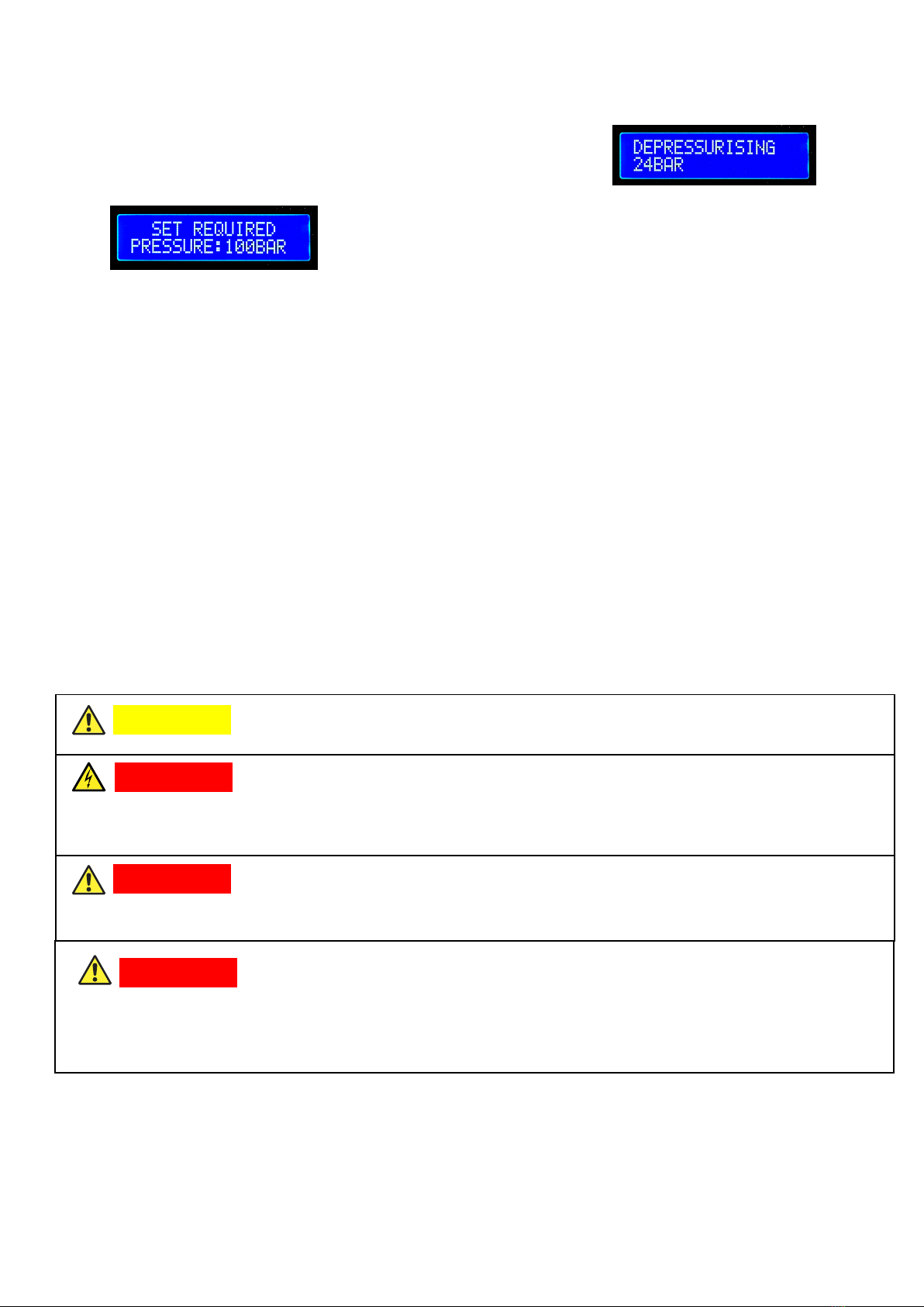
DO NOT disconnect the cylinder until the compressor has been depressurised
Depressurise by releasing the bleed screw. Whilst
depressurising, the compressor will expel some moisture and
a small amount of lubricant. Suitable precautions should be
taken to protect any floor coverings under the compressor.
8
The display will show the progress of the depressurisation
until it reaches the minimum display value 0BAR. You can
disconnect the cylinder.
The display will revert to the “set required pressure screen”
After one accumulative hour of pumping, the compressor will stop and request that you
check the lubricant levels. The compressor will not restart until you press the control knob. If
connected to a large diving cylinder, close the valve on the cylinder and take this opportunity
to depressurise/drain the compressor.
DO NOT LEAVE THE COMPRESSOR UNATTENDED WHEN IN USE!
IN THE UNLIKELY EVENT THAT YOUR COMPRESSOR MALFUNCTIONS, DO NOT
ATTEMPT TO FIX THE PROBLEM YOURSELF. PLEASE CALL THE DISTRIBUTOR
YOU PURCHASED IT FROM.
PLEASE RETAIN THE ORIGINAL RECEIPT OF PURCHASE
The most up to date version of this instructions manual will be available at www.hillpumps.com
Please check this website regularly
PARTS OF THIS COMPRESSOR GET VERY HOT. DO NOT TOUCH THESE HOT PARTS
DO NOT TOUCH MOVING PARTS, FOR EXAMPLE THE COOLING FAN.
KEEP FINGERS AND LOOSE CLOTHING AWAY FROM MOVING PARTS
WARNING
DANGER
WARNING
DANGER OF ELECTRIC SHOCK
DO NOT OPERATE OUTSIDE IN THE RAIN
DO NOT OPERATE WITH WET HANDS OR WET CLOTHES
DANGER

Troubleshooting
9
Closedown
Storage
Maintenance
- Compressor will not start
Make sure that the power cable is inserted correctly and that the
compressor is switched on, check that the fuse in the switch has
not blown
- Pressure does not exceed 50BAR and air escapes from the Pressure
Relief Valve
See maintenance on website for Disc Valve cleaning
- Pressure asked for on compressor is not pressure in cylinder
Cylinder valve may cause small pressure loss, adjust pressure on
compressor to compensate
Make sure that the cylinder is removed and bleed screw is opened to release
pressure
Keep upright at all times
Change both lubricants every 50 running hours or once yearly (whichever
comes first)
Unscrew sight glass to change Crank Oil (make sure you have a
suitable container underneath) and drain.
Unscrew silicone oil bottle and change oil.
ERNEST H. HILL LIMITED
L
ONGACRE WAY - HOLBROOK - SHEFFIELD S20 3FS - ENGLAND
T
elephone; +44 (0) 114 248 4882
www.hillpumps.com sales@hillpumps.com
Other manuals for EC-3000
2
Table of contents
Other HILL PUMPS Air Compressor manuals


Popular Air Compressor manuals by other brands


Campbell Hausfeld
Campbell Hausfeld FP260100 Easy setup guide

KAESER
KAESER CSD 75 Service manual

Comprag
Comprag A7510 manual

Gardner Denver
Gardner Denver GD150 Installation operating & maintenance manual

Probuilder
Probuilder 43660 instruction manual

Daikin
Daikin VRV IV RKXYQ5T8Y1B Series Installation and operation manual

Scheppach
Scheppach 7906100712 Translation of the original instruction manual

Danfoss
Danfoss Turbocor TT-300 Service manual

Sullair
Sullair TS-20 Operator's manual and parts list

Gardner Denver
Gardner Denver EBB BB-7.5 HP Operating and service manual

MODE
MODE HS08-6 Series instruction manual

Campbell Hausfeld
Campbell Hausfeld Vertical Operating instrctions