Hill 3900 User manual

Model 3900 Downow
Service Manual
IMPORTANT: Fill in Pertinent Information on Page 3 for Future Reference

Table of Contents
IMPORTANT PLEASE READ:
The information, specications and illustrations in this manual are based on the latest information available at the time of
printing. The manufacturer reserves the right to make changes at any time without notice.
This manual is intended as a guide for service of the valve only. System installation requires information from a number of
suppliers not known at the time of manufacture. This product should be installed by a plumbing professional.
This unit is designed to be installed on potable water systems only.
This product must be installed in compliance with all state and municipal plumbing and electrical codes. Permits may be
required at the time of installation.
If daytime operating pressure exceeds 80 psi, nighttime pressures may exceed pressure limits. A pressure reducing valve must
be installed.
Do not install the unit where temperatures may drop below 32°F (0°C) or above 110°F (43°C).
Do not place the unit in direct sunlight. Black units will absorb radiant heat increasing internal temperatures.
Do not strike the valve or any of the components.
Warranty of this product extends to manufacturing defects of the vessel and controller, not the membrane. Misapplication of this
product may result in failure to properly condition water, or damage to product.
A prelter should be used on installations in which free solids are present.
In some applications local municipalities treat water with Chloramines. High Chloramine levels may damage valve components.
Correct and constant voltage must be supplied to the control valve to maintain proper function.
•
•
•
•
•
•
•
•
•
•
•
•

Job No. ___________________________________________________________________________________
Model No. _________________________________________________________________________________
Water Test _________________________________________________________________________________
Capacity Per Unit ___________________________________________________________________________
Mineral Tank Size _____________ Diameter ____________ Height _______________
Brine Tank Size & Salt Setting per Regeneration ___________________________________________________
2900s Control Valve Specications
1. Type of Timer
A. 7 Day or 12 Day
B. 3,750 to 63,750 Gallon Meter or
18,750 to 318,750 Gallon Meter or
Other ________________________________
C. Meter Wiring Package
1. System #4 - 1 Tank, 1 Meter, Immediate or Delayed Regeneration
2. System #5 - 2 Tanks, 2 Meters, Interlock
3. System #6 - 2 Tanks, 1 Meter, Series Regeneration
4. System #7 - 2 Tanks, 1 Meter, Alternator
2. Timer Program Settings
A. Backwash _________________________ Minutes
B. Brine & Slow Rinse __________________ Minutes
C. Rapid Rinse ________________________ Minutes
D. Brine Tank Rell _____________________ Minutes
3. Drain Line Flow Control __________________ gpm
4. Brine Line Flow Controller ________________ gpm
5. Injector Size # _________________________
6. A. Hard Water Bypass
B. No Hard Water Bypass
Page 3
Job Specication Sheet

Page 4
General Commercial Pre-Installation Check List
WATER PRESSURE: A minimum of 25 pounds of water pressure is required for regeneration valve to operate
effectively.
ELECTRICAL FACILITIES: A continuous 115 volt, 60 Hertz current supply is required. Make certain the current
supply is always hot and cannot be turned off with another switch.
EXISTING PLUMBING: Condition of existing plumbing should be free from lime and iron buildup. Piping that is
built up heavily with lime and/or iron should be replaced. If piping is clogged with iron, a separate iron lter unit
should be installed ahead of the water softener.
LOCATION OF SOFTENER AND DRAIN: The softener should be located close to a drain.
BY-PASS VALVES: Always provide for the installation of a by-pass valve.
CAUTION: Water pressure is not to exceed 125 p.s.i., water temperature is not to exceed 110° F, and the unit
cannot be subjected to freezing conditions.
Installation Instructions
1. Place the softener tank where you want to install the unit making sure the unit is level and on a rm base.
(Maximum 4 feet apart for twin units)
2. All plumbing should be done in accordance with local plumbing codes. The pipe size for the drain line should
be the same size as the drain line ow control connection. Water meters are to be installed on soft water
outlets. Twin units with 1 meter shall be installed on common soft water outlet of units.
3. Solder joints near the drain must be done prior to connecting the Drain Line Flow Control tting. Leave at
least 6” between the DLFC and solder joints when soldering when the pipes are connected on the DLFC.
Failure to do this could cause interior damage to the DLFC.
4. Teon tape is the only sealant to be used on the drain tting. The drain from twin units may be run through a
common line.
5. Make sure that the oor is clean beneath the salt storage tank and that it is level.
6 Place approximately 1” of water above the grid plate (if used) in your salt tank. Salt may be placed in the unit
at this time.
7. Place in by-pass position. Turn on the main water supply. Open a cold soft water tap nearby and let run a few
minutes or until the system is free from foreign material (usually solder) that may have resulted from the
installation.
8. Place the by-pass in service position.
9. Manually index the softener control into “service” position and let water ow into the mineral tank. When water
ow stops, close inlet valve, place control in “backwash” position to relieve head of air, then gradually open
inlet valve to purge remaining air in tank. Return control to service position.
10. Electrical: All electrical connections must be connected according to codes. Use electrical conduit if
applicable. Plug into power supply.

Page 5
3200 Timer Setting Procedure
How To Set Days On Which Water Conditioner Is To
Regenerate:
Rotate the skipper wheel until the number “1” is at the
red pointer. Set the days that regeneration is to occur
by sliding tabs on the skipper wheel outward to expose
trip ngers. Each tab is one day. Finger at red pointer is
tonight. Moving clockwise from the red pointer, extend
or retract ngers to obtain the desired regeneration
schedule.
How To Set The Time Of Day:
1. Press and hold the red button in to disengage the
drive gear.
2. Turn the large gear until the actual time of day is at
the time of day pointer.
3. Release the red button to again engage the drive
gear.
How To Manually Regenerate Your Water
Conditioner At Any Time:
1. Turn the manual regeneration knob clockwise.
2. This slight movement of the manual regeneration
knob engages the program wheel and starts the
regeneration program.
3. The black center knob will make one revolution in
the following approximately three hours and stop in
the position shown in the drawing.
4. Even though it takes three hours for this center knob
to complete one revolution, the regeneration cycle of
your unit might be set only one half of this time.
5. In any event, conditioned water may be drawn after
rinse water stops owing from the water
conditioner drain line.
How to Adjust Regeneration Time:
1. Disconnect the power source.
2. Locate the three screws behind the manual
regeneration knob by pushing the red button in and
rotating the 24 hour dial until each screw appears in
the cut out portion of the manual regeneration knob.
3. Loosen each screw slightly to release the pressure
on the time plate from the 24 hour gear.
4. Locate the regeneration time pointer on the inside
of the 24 hour dial in the cut out.
5. Turn the time plate so the desired regeneration time
aligns next to the raised arrow.
6. Push the red button in and rotate the 24 hour dial.
Tighten each of the three screws.
7. Push the red button and locate the pointer one more
time to ensure the desired regeneration time
is correct.
8. Reset the time of day and restore power to the unit.

Page 6
3210 Timer Settings
Typical Programming Procedure
Calculate the gallon capacity of the system, subtract
the necessary reserve requirement and set the gallons
available opposite the small white dot on the program
wheel gear.
NOTE: Drawing shows 8,750 gallon setting. The
capacity (gallons) arrow denotes remaining gallons
exclusive of xed reserve.
How To Set The Time Of Day:
Press and hold the red button in to disengage the
drive gear.
Turn the large gear until the actual time of day is
opposite the time of day pointer.
Release the red button to again engage the drive
gear.
1.
2.
3.
How To Manually Regenerate Your Water
Conditioner At Any Time:
Turn the manual regeneration knob clockwise.
This slight movement of the manual regeneration
knob engages the program wheel and starts the
regeneration program.
The black center knob will make one revolution in
the following approximately three hours and stop in
the position shown in the drawing.
Even though it takes three hours for this center
knob to complete one revolution, the regeneration
cycle of your unit might be set for only one half of
this time.
In any event, conditioned water may be drawn after
rinse water stops owing from the water conditioner
drain line.
Immediate Regeneration Timers:
These timers do not have a 24 hour gear. Setting the
gallons on the program wheel and manual regeneration
procedure are the same as previous instructions.
1.
2.
3.
4.
5.
NOTE: To set meter capacity
rotate manual knob one - 360°
revolution to set gallonage.

Page 7
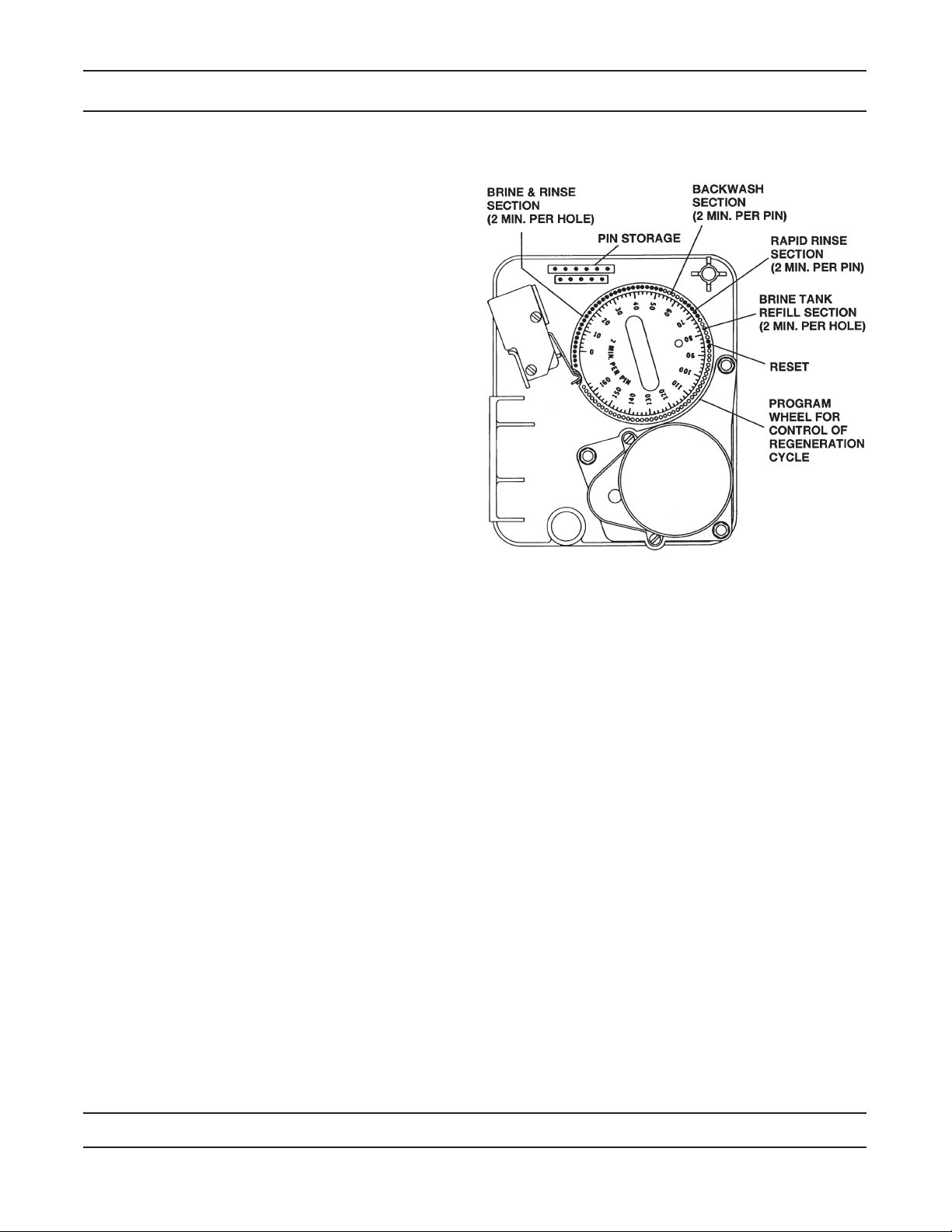
3200 & 3210 Timer Series
How To Set The Regeneration Cycle Program:
The regeneration cycle program on your water
conditioner has been factory preset, however,
portions of the cycle or program may be lengthened or
shortened in time to suit local conditions.
3200 & 3210 Series Timers (Figure to Right)
To expose cycle program wheel, grasp timer in
upper left-hand corner and pull, releasing snap
retainer and swinging timer to the right.
To change the regeneration cycle program, the
program wheel must be removed. Grasp program
wheel and squeeze protruding lugs toward center,
lift program wheel off timer. (Switch arms may
require movement to facilitate removal)
Return timer to closed position engaging snap
retainer in back plate. Make certain all electrical
wires locate above snap retainer post.
Timer Setting Procedure for 3200 & 3210
Timer
How To Change The Length Of The Backwash
Time:
The program wheel as shown in the drawing is in the
service position. As you look at the numbered side of
the program wheel, the group of pins starting at zero
determines the length of time your unit will backwash.
EXAMPLE: If there are six pins in this section, the time
of backwash will be 12 min. (2 min. per pin). To change
the length of backwash time, add or remove pins as
required. The number of pins times two equals the
backwash time in minutes.
How To Change The Length Of Brine And Rinse
Time:
The group of holes between the last pin in the
backwash section and the second group of pins
determines the length of time that your unit will
brine and rinse (2 min. per hole.)
To change the length of brine and rinse time, move
the rapid rinse group of pins to give more or fewer
holes in the brine and rinse section. Number of
holes times two equals brine and rinse time in
minutes.
1.
2.
3.
1.
2.
How To Change The Length Of Rapid Rinse:
The second group of pins on the program wheel
determines the length of time that your water
conditioner will rapid rinse. (2 min. per pin.)
To change the length of rapid rinse time, add or
remove pins at the higher numbered end of this
section as required. The number of pins times two
equals the rapid rinse time in minutes.
How To Change The Length Of Brine Tank Rell
Time:
The second group of holes in the program wheel
determines the length of time that your water
conditioner will rell the brine tank (2 min. per hole.)
To change the length of rell time, move the two
pins at the end of the second group of holes as
required.
The regeneration cycle is complete when the outer
microswitch is tripped by the two pin set at end of
the brine tank rell section.
The program wheel, however, will continue to rotate
until the inner micro-switch drops into the notch on
the program wheel.
1.
2.
1.
2.
3.
4.
Regeneration Cycle Program Setting Procedure - Downow
Page 8
3200 & 3210 Timer Series
How To Set The Regeneration Cycle Program:
The regeneration cycle program on your water
conditioner has been factory preset, however,
portions of the cycle or program may be lengthened or
shortened in time to suit local conditions.
3200 & 3210 Series Timers (Figure to Right):
To expose cycle program wheel, grasp timer in upper
left-hand corner and pull, releasing snap retainer and
swinging timer to the right
To change the regeneration cycle program, the
program wheel must be removed. Grasp program
wheel and squeeze protruding lugs toward center, lift
program wheel off timer. (Switch arms may require
movement to facilitate removal.)
Return timer to closed position engaging snap retainer
in back plate. Make certain all electrical wires locate
above snap retainer post.
Timer Setting Procedure for 3200 & 3210
Timer
How To Change The Length Of The Backwash
Time:
The program wheel as shown in the drawing is in the
service position. As you look at the numbered side of
the program wheel, the group of pins starting at zero
determines the length of time your unit will backwash.
EXAMPLE: If there are six pins in this section, the time
of backwash will be 12 min. (2 min. per pin). To change
the length of backwash time, add or remove pins as
required. The number of pins times two equals the
backwash time in minutes.
How To Change The Length Of Brine And Rinse
Time:
The group of holes between the last pin in the
backwash section and the second group of pins
determines the length of time that your unit will brine
and rinse (2 min. per hole.)
To change the length of brine and rinse time, move the
rapid rinse group of pins to give more or fewer holes in
the brine and rinse section. Number of holes times two
equals brine and rinse time in minutes.
How To Change The Length Of Rapid Rinse:
The second group of pins on the program wheel
determines the length of time that your water
conditioner will rapid rinse. (2 min. per pin.)
To change the length of rapid rinse time, add or remove
pins at the higher numbered end of this section as
required. The number of pins times two equals the
rapid rinse time in minutes.
How To Change The Length Of Brine Tank Rell
Time:
The second group of holes in the program wheel
determines the length of time that your water
conditioner will rell the brine tank (2 min. per hole.)
To change the length of rell time, move the two pins at
the end of the second group of holes as required.
The regeneration cycle is complete when the outer
microswitch is tripped by the two pin set at end of the
brine tank rell section. The program wheel, however,
will continue to rotate until the inner micro-switch drops
into the notch on the program wheel.
Regeneration Cycle Program Setting Procedure - Upow

Page 9
Notes

Page 10
3210 Timer Assembly
61502-3210_REVA
For Service Assembly Numbers, See the Back of this Manual

Page 11
3210 Timer Assembly
Item No. Quantity Part No. Description
1..................1...................13870 ......................Housing, Timer, 3200
2..................1...................13802 ......................Gear, Cycle Actuator
3..................1...................40096-02.................Dial 2AM Regen Assy, Black
4..................1...................13886 ......................Knob, 3200
5..................4...................13296 ......................Screw, Hex Wsh, 6-20 x 1/2
6..................2...................11999 ......................Label, Button
7..................1...................60405-50.................Program Wheel, w/2” Std Label
8..................1...................13806 ......................Retainer, Program Wheel
9..................1...................13748 ......................Screw, Flat Head St, 6-20 x 1/2
10................1...................14265 ......................Clip, Spring
11................1...................15424 ......................Spring, Detent, Timer
12................1...................15066 ......................Ball, 1/4” Delrin
13................1...................13018 ......................Pinion, Idler
14................1...................13312 ......................Spring, Idler Shaft
15................1...................13017 ......................Gear, Idler
16................1...................13164 ......................Gear, Drive
17................1...................13887 ......................Plate, Motor Mounting
18................1...................18743-1...................Motor, 120V, 60Hz 1/30 RPM, 5600
19................1...................13278 ......................Screw, Fillister Hd, 6-32 x .156
20................1...................13830 ......................Pinion, Program Wheel Drive
21................1...................13831 ......................Clutch, Drive Pinion
22................1...................14276 ......................Spring, Meter, Clutch
23................1...................14253 ......................Retainer, Clutch Spring
24................3...................11384 ......................Screw, Phil, 6-32 x 1/4
25................1...................13881 ......................Bracket, Hinge Timer
26................3...................14087 ......................Insulator
27................1...................10896 ......................Switch, Micro
28................1...................15320 ......................Switch, Micro, Timer
29................2...................11413 ......................Screw, Pan Hd Mach, 4-40 x 1 1/8
30................1...................14198 ......................Label, Indicator
31................1...................15465 ......................Label, Caution
32................1...................14007 ......................Label, Time of Day
33................1...................14045 ......................Label, Instruction
34................1...................13902 ......................Harness, 3200
35................2...................40422 ......................Nut, Wire, Tan
36................1...................15354-01.................Wire, Ground, 4”
37................1...................19210 ......................Program Wheel Assy
38................17 .................41754 ......................Pin, Spring, 1/16 x 5/8 SS, Timer
39................1...................13911 ......................Gear, Main Drive, Timer
40................1...................15354-01.................Wire, Ground 4”
For Service Assembly Numbers, See the Back of this Manual

Page 12
Powerhead Assembly
For Service Assembly Numbers, See the Back of this Manual

Page 13
Powerhead Assembly
For Service Assembly Numbers, See the Back of this Manual

Page 14
Powerhead Assembly
For Service Assembly Numbers, See the Back of this Manual

Page 15
Powerhead Assembly
For Service Assembly Numbers, See the Back of this Manual

Page 16
Control Valve Assembly
For Service Assembly Numbers, See the Back of this Manual
10
13 14
5
2
8
6
4
1
3
16
25
17 16
17
19
8
13
22
11
24
12
9
13 7
14 13
151314
131413
15
1314
20
21
18
16
17
23
23

Page 17
Control Valve Assembly
For Service Assembly Numbers, See the Back of this Manual
Item No. Quantity Part No. Description
1................... 1.................... 16067-02.................VALVE BODY,3900,AUX TAP
2................... 1.................... 15114 ......................VALVE BODY,3150
3................... 1.................... 16258......................FLOW STRAIGHTENER,3900
4................... 1.................... 15112 ......................SEAL,3150 ADAPTER BASE
5................... 2.................... 40118 ......................SCREW,SCKT HD,1/2-13 UNC
6................... 1.................... 16088......................PLUG,BRASS,2”,NPT,3900
7................... 1.................... 16078......................O-RING,-149,3900
8................... 1.................... 16074......................COUPLING,ADAPTER,3900
9................... 1.................... 16077......................O-RING,-140
10................. 1.................... 16130......................PISTON,HIGH BACKWASH
11................. 1.................... 15125......................ROD,PISTON,3150
12................. 2.................... 14818......................RING,PISTON ROD,SNAP
13................. 8.................... 11720 ......................SEAL,PISTON,2900/3150
14................. 5.................... 10369......................SPACER,2”,2900/3150
15................. 2.................... 10368......................SPACER,NARROW,3150/3900
16................. 4.................... 16068......................SEAL,3900
17................. 2.................... 16069......................SPACER,3900
18................. 1.................... 16070......................SPACER,3900
19................. 1.................... 16071......................SPACER,3900
20................. 1.................... 16072......................ROD,PISTON,3900,LOWER
21................. 1.................... 16076......................O-RING,-042,3900
22................. 1.................... 15118-01 .................PLUG,END,3150,NATURAL,MACHINED
23................. 2.................... 11242 ......................QUAD RING,-112,560CD
24................. 1.................... 14922......................O-RING,-035,PISTON
25................. 1.................... 16073-01.................PLUG,END,NATURAL
3900 Mounting Kits (Options):
............................................ 60190......................Flange Kit, Park & Structural
............................................ 60192......................Flange Kit, Welded
............................................ 60193......................Flange Kit, 6” Threaded
............................................ 61417......................Fixed Sidemount (NPT)
............................................ 61417-22.................Fixed Sidemount (BSP)

Page 18
1800 Brine Assembly
For Service Assembly Numbers, See the Back of this Manual
60036_REVA

Page 19
1800 Brine Assembly
For Service Assembly Numbers, See the Back of this Manual
Item No. Quantity Part No. Description
1................... 1.................... 16340......................Body, Injector, 1800 D/F
2................... 1.................... 15128-xx .................Injector Nozzle
3................... 1.................... 15127-xx .................Injector Throat
4................... 3.................... 15246......................O-ring, -116
5................... 1.................... 16341-01.................Cap, Injector, 1800
6................... 8.................... 12473......................Screw, Hex Wsh, 10-24 x 5/8
7................... 1.................... 16341-02.................Plug, Injector, 1800
8................... 1.................... 13303-01.................O-ring, -021, 560CD
9................... 1.................... 16497-01.................Stem Assy, 1800, Brine Valve
10................. 1.................... 18713......................Brine Valve Body, 1800
11................. 1.................... 11772 ......................Spring, 3150 Brine Valve
12................. 1.................... 11774 ......................Ring, Retaining
13................. 1.................... 16498-01.................Stem Guide Assy, Brine
14................. 1.................... 16387......................Plug, Pipe, 1/2” NPT
15................. 2.................... 18702......................Fitting, Tube, 1/2 NPT 5/8
16................. 1.................... 18703......................Tube, Brine, 5/8 OD Annealed
17................. 1.................... 60009-00.................Air Check, #900, Commercial Less Fittings
60009-01.................Air Check, #900, Commercial, HW Less Fittings
Not Shown ... 1.....................................................Flow Control (Specify Flow Rate)
Option Without Brine Valve
1..............................16605......... Retainer Plate
1..............................19860......... Fitting, Brine Valve, 1800
Delete: Items 9 through 16
Injector Throat
15127-04.................#4............... Green
15127-05.................#5............... Red
15127-06.................#6............... White
15127-07.................#7............... Blue
15127-08.................#8............... Yellow
15127-09.................#9............... Violet
15127-10.................#10............. Black
Injector Nozzle
15128-04.................#4............... Green
15128-05.................#5............... Red
15128-06.................#6............... White
15128-07.................#7............... Blue
15128-08.................#8............... Yellow
15128-09.................#9............... Violet
15128-10.................#10............. Black

Page 20
3” Brass Meter Assembly
For Service Assembly Numbers, See the Back of this Manual
Item No. Quantity Part No. Description
1................... 1.................... 16254......................Meter Body
2................... 1.................... 16279......................Impeller Shaft
3................... 1.................... 16575......................Impeller Assembly
4................... 1.................... 16400......................Meter Cover Assembly - Std.
..................... 1.................... 16401......................Meter Cover Assembly - Ext. Range
5................... 3.................... 15707......................O-Ring - 236
6................... 6.................... 12112 ......................Screw - Hex Hd.
..................... 6.................... 15886......................Screw - Hex Hd. (Metric)
7................... 1.................... 16280......................Flow Straightener
8................... 2.................... 16328......................Connecting Flange
9................... 8.................... 40118 ......................Screw - Hex Hd.
..................... 8.................... 17122......................Screw - Hex Hd. (Metric)
10................. 8.................... 16386......................Nut - 1/2-13
11................. 1.................... 16574......................Stainless Steel Washer
Table of contents
Popular Water Dispenser manuals by other brands


Aqua To Go
Aqua To Go Argento Cleaning instructions

DS Services of America
DS Services of America 200K Series How to Clean

BRIO
BRIO CLCTPOU720UVF3 Setup manual

Pelican Water Technologies
Pelican Water Technologies PS48 owner's manual

TZS First AUSTRIA
TZS First AUSTRIA FA-5448-6 instruction manual

Follett
Follett VU155N Series Specifications

Lancaster
Lancaster City Soft Plus XFactor Series Installation, operating and service manual

SYR
SYR IT 4000 Instructions for use

Oasis
Oasis POU_1RREC Series Installation & service instructions

Zip
Zip 801912UK user manual

MrCool
MrCool MTWB05 Owners & installation manual

Bunn
Bunn H5E Installation & operating guide