Hillrom Itegris 2001B User manual

DRAFT 08/27/03
INSTALLATION INSTRUCTIONS
Integris® 2001B
Headwall System
and Vertical Chase
(with and without a
Breaker Panel)
From Hill-Rom
Product No. P2001B
For Parts or Technical Assistance is444rc
Technical Support: (800) 445-3720
Customer Service: (800) 445-3730
Canada: (800) 267-2337
International: Contact your distributor.
www.hill-rom.com
For Parts or Technical Assistance is444re
Technical Support: (800) 445-3720
Customer Service: (800) 445-3730
Canada: (800) 267-2337
International: Contact your distributor.
www.hill-rom.com


October 13, 2003 is444re Page i
08/27/03 DRAFT
Integris® 2001B Headwall
System and Vertical Chase
(with and without
a Breaker Panel)
Installation Instructions
is444re
Revision Letter Pages Affected Date
Original Issue May, 2000
A All August, 2000
B 1, 19, and 20 November, 2000
C All April, 2001
D All October, 2001
E All October, 2003

Page ii is444re October 13, 2003
08/27/03 DRAFT
© 2003 by Hill-Rom Services, Inc. ALL RIGHTS RESERVED.
No part of this text shall be reproduced or transmitted in any form or by any
means, electronic or mechanical, including photocopying, recording, or by any
information or retrieval system without written permission from Hill-Rom
Services, Inc. (Hill-Rom).
The information in this document is confidential and may not be disclosed to
third parties without the prior written consent of Hill-Rom.
Sixth Edition
First Printing 2000
Printed in the USA
E-Z Ancor® is a registered trademark of Illinois Tool Works, Inc.
Hill-Rom® is a registered trademark of Hill-Rom Services, Inc.
Integris® is a registered trademark of Hill-Rom Services, Inc.
National Electrical Code® is a registered trademark of National Fire Protection
Association, Inc.
NEC® is a registered trademark of National Fire Protection Association, Inc.
The information contained in this document is subject to change without
notice. Hill-Rom makes no commitment to update or keep current, the
information contained in this manual.
The only product warranty intended by Hill-Rom is the express, written
warranty accompanying the bill of sale to the original purchaser. Hill-Rom
makes no other warranty, express or implied, and in particular, makes no
warranty of merchantability or fitness for a particular purpose.
Additional copies of this document can be obtained from Hill-Rom.

October 13, 2003 is444re Page iii
DRAFT 08/27/03
Table of Contents
Introduction. . . . . . . . . . . . . . . . . . . . . . . . . . . . . . . . . . . . . . . . . . . . . . . . . . . . . . . . . . 1
Order of Installation . . . . . . . . . . . . . . . . . . . . . . . . . . . . . . . . . . . . . . . . . . . . . . . . . . . 3
Fastener Identification . . . . . . . . . . . . . . . . . . . . . . . . . . . . . . . . . . . . . . . . . . . . . . . . . 5
Determining the Wall/Construction Type. . . . . . . . . . . . . . . . . . . . . . . . . . . . . . . . . . . 7
Installing the Medical Gas Drops . . . . . . . . . . . . . . . . . . . . . . . . . . . . . . . . . . . . . . . . . 7
Installing the Vertical Chase with a Breaker Panel . . . . . . . . . . . . . . . . . . . . . . . . . . . 9
Installing the Hanger Bracket . . . . . . . . . . . . . . . . . . . . . . . . . . . . . . . . . . . . . . . . . 9
Installing the Vertical Chase. . . . . . . . . . . . . . . . . . . . . . . . . . . . . . . . . . . . . . . . . 11
Installing the Vertical Chase without a Breaker Panel . . . . . . . . . . . . . . . . . . . . . . . . 13
Installing the Raceway . . . . . . . . . . . . . . . . . . . . . . . . . . . . . . . . . . . . . . . . . . . . . . . . 16
Installing the Raceway Hanger Bracket(s) . . . . . . . . . . . . . . . . . . . . . . . . . . . . . . 16
Positioning and Mounting a Single Raceway Section . . . . . . . . . . . . . . . . . . . . . 19
Mounting Multiple Raceway Sections . . . . . . . . . . . . . . . . . . . . . . . . . . . . . . . . . 21
Connecting the Gas Pipe. . . . . . . . . . . . . . . . . . . . . . . . . . . . . . . . . . . . . . . . . . . . 22
Installing the Covers. . . . . . . . . . . . . . . . . . . . . . . . . . . . . . . . . . . . . . . . . . . . . . . . . . 23
Installing the Raceway Gas Pipe Cover . . . . . . . . . . . . . . . . . . . . . . . . . . . . . . . . 23
Installing the Splice Covers . . . . . . . . . . . . . . . . . . . . . . . . . . . . . . . . . . . . . . . . . 23
Installing the Covers on the Vertical Chase with a Breaker Panel. . . . . . . . . . . . 23
Installing the Covers on the Vertical Chase without a Breaker Panel . . . . . . . . . 23

Table of Contents
Page iv is444re October 13, 2003
DRAFT 08/27/03
NOTES:

October 13, 2003 is444re Page 1 of 24
DRAFT 08/27/03
Subject: Integris® 2001B Headwall System and Vertical Chase (with and
without a Breaker Panel) Installation Instructions
Introduction
This installation instruction sheet describes how to install the Integris® 2001B Headwall
System raceway (A) and vertical chase (with a breaker panel) (B) or the vertical chase
(without a breaker panel) (C) (see figure 1 on page 1).
Figure 1. Integris® 2001B Headwall System and Vertical Chase
Prior to installation, carefully read all of the installation instructions for the components you
are installing.
WARNING:
For installation of the Integris® 2001B Headwall System (fire-rated/non-
seismic), ensure that the walls are constructed of at least 20 gauge steel studs
on 16" (41 cm) centerlines, and covered with a minimum of 5/8" (15.9 mm) dry
wall. Failure to do so could result in the collapse of the Integris® 2001B
Headwall System. Personal injury or equipment damage could occur.

Page 2 of 24 is444re October 13, 2003
DRAFT 08/27/03
Before installation of the headwall system components, the facility’s medical gases and
vacuum lines should have been run to the general location according to NFPA 99 and NFPA
70, National Electric Code®1(NEC®2).
Tools required: Standard drill/power screwdriver
#2 phillips head screwdriver
¼" drill bit
Medium screwdriver
½" spade bit
Large screwdriver
7/8" spade bit
11/32" open end wrench
1" spade bit
5/16" hex head nutdriver
Ratchet wrench
3/8" hex head nutdriver
9/16" deep socket with 3" extension
Tape measure
Level
Chalk line
Rubber mallet or block and hammer
Ladder
Adjustable wrench
Parts required: (1) 205935 Splice cover top, complete
(1) 205934 Splice cover lower, 2001
Related Documents:Integris® B Lite Rail Installation Instructions (is443)
1. National Electric Code® is a registered trademark of National Fire Protection Association, Inc.
2. NEC® is a registered trademark of National Fire Protection Association, Inc.

October 13, 2003 is444re Page 3 of 24
DRAFT 08/27/03
Order of Installation
The numbered steps below correspond with the order of installation for the listed components.
1. Determine the type of wall (D) and construction type (see figure 2 on page 4).
2. Install the medical gas drops (E).
3. Perform one of the following:
• To install the vertical chase (with a breaker panel) (B), install the vertical chase
hanger bracket and the vertical chase with a breaker panel (B).
• Install the vertical chase (without a breaker panel) (C).
4. To install the raceway (A), perform the following:
a. Install the raceway hanger bracket (F).
b. Position and install a single section of raceway (A).
c. Mount multiple sections of raceway (A).
d. Connect the gas pipe.
5. To install the covers, perform the following:
a. Install the gas pipe cover (G).
b. Install the vertical chase bottom cover (H).

Page 4 of 24 is444re October 13, 2003
DRAFT 08/27/03
Figure 2. Component Identification

October 13, 2003 is444re Page 5 of 24
DRAFT 08/27/03
Fastener Identification
The fasteners in the following installation instructions are referred to by callout letter (see
table 1 on page 5) and (see figure 3 on page 6).
Table 1. Fastener Callout Letters
Callout Letter Description
I Screw, #12-14 x 1½", self-drilling, hex head
J Cup washer
K Screw, 3/8"-16 x 3", slotted round
L Toggle wing, 3/8"-16
M Installation clip
N Screw, #6 x 3/8", truss head
O Screw, #12-14 x ½", type AB, hex head
P Transition pin
Q #8-32 locknut
R Screw, #6-20 x 3/8", flat head
S Top splice cover
T Screw, #8-32 x ½", pan head
UE-Z Ancor®ascrew anchor
a. E-Z Ancor® is a registered trademark of Illinois Tool Works, Inc.
V Screw, #8-18 x 7/8", pan head
W Lower splice cover
X Screw, #10-32 x ½", pan head

Page 6 of 24 is444re October 13, 2003
DRAFT 08/27/03
Figure 3. Fasteners

October 13, 2003 is444re Page 7 of 24
DRAFT 08/27/03
Determining the Wall/Construction Type
WARNING:
The installation method differs for each wall and construction type. Failure to
determine the wall and construction type could result in personal injury or
equipment damage.
1. Before proceeding, refer to the local or state building codes, and determine the type of
wall (D) and construction type (see figure 2 on page 4):
•Seismic walls are constructed to prevent damage from an earthquake.
•Non-seismic walls are not constructed to prevent damage from an earthquake.
•Fire-rated walls are constructed to prevent the spread of fire.
•Non-fire-rated walls are not constructed to prevent the spread of fire.
2. Perform one of the following:
•Onseismic walls, install the wall backing plates according to the Office of
Statewide Health, Planning, and Development (OSHPD)-approved drawings
and the as-built drawings, and then go to “Installing the Medical Gas Drops”
on page 7.
NOTE:
For seismic construction requirements, contact Hill-Rom Technical Support at
800-445-3720.
•Onnon-seismic walls (both fire and non-fire-rated), go to “Installing the Med-
ical Gas Drops” on page 7.
Installing the Medical Gas Drops
1. To locate the connections to the medical gas supplies, refer to the as-built drawings for
the Integris® 2001B Headwall System.
2. Ensure that the connections to the medical gas supply are located in the center of the
vertical chase (B) or (C), with the oxygen supply connection oriented closest to the
raceway (A) (see figure 4 on page 8). If the connections are not properly located, a
contractor must relocate them.
3. Install the medical gas service drops.

Page 8 of 24 is444re October 13, 2003
DRAFT 08/27/03
Figure 4. Medical Gas Drops
Finished floor

October 13, 2003 is444re Page 9 of 24
DRAFT 08/27/03
4. Perform one of the following (see figure 2 on page 4):
• On a vertical chase with a breaker panel (B), go to “Installing the Vertical
Chase with a Breaker Panel” on page 9.
• On a vertical chase without a breaker panel (C), go to “Installing the Vertical
Chase without a Breaker Panel” on page 13.
Installing the Vertical Chase with a Breaker Panel
Installing the Hanger Bracket
NOTE:
Before installing a vertical chase with a breaker panel, you must install a chase hanger
bracket.
WARNING:
The installation method differs for each wall and construction type. Failure to
determine the wall and construction type could result in the collapse of the
Integris® 2001B Headwall System. Personal injury or equipment damage
could occur.
1. Ensure that the wall meets the required specifications:
•Onnon-seismic construction, make certain the walls are constructed of at least
20 gauge steel studs on 16" (41 cm) centerlines and covered with a minimum
of 5/8" (15.9 mm) dry wall.
•Onseismic construction requirements, contact Hill-Rom Technical Support at
800-445-3720.
2. If installing a vertical chase (B) against a corner wall, allow a minimum of 1/16"
(1.6 mm) for the vertical trim between the vertical chase (B) and the side wall (see fig-
ure 5 on page 10).
3. For the location and height of the vertical chase (B), refer to the as-built drawings.
4. From the ceiling (Y), measure down the height of the vertical chase (B), and strike a
level horizontal line (Z).
5. Locate the side of the vertical chase (B) on the end of raceway on the horizontal line
(Z).
6. To locate the end of the chase hanger bracket (AA), measure 3/8" (9.5 mm) in from the
side of the vertical chase (B).
7. Remove the chase hanger bracket (AA) from the bottom of the vertical chase (B), and
save the fasteners.

Page 10 of 24 is444re October 13, 2003
DRAFT 08/27/03
Figure 5. Vertical Chase with a Breaker Panel Hanger Bracket Installation
Refer to as-built drawings
Bed centerline

October 13, 2003 is444re Page 11 of 24
DRAFT 08/27/03
8. Align the bottom surface of the chase hanger bracket (AA) with the horizontal line (Z).
9. On non-fire-rated walls, perform the following:
a. On the wall (D), mark both pairs of 1" holes (AB) in the chase hanger bracket
(AA).
b. At each pair of 1" (3 cm) holes (AB), drill only one of the 1" (3 cm) holes in the
dry wall. If an obstruction or wall stud is encountered, use the alternate 1" (3
cm) hole (AB).
10. Perform one of the following:
•Onnon-seismic, non-fire-rated walls, install the slotted round screw (K),
toggle wings (L), and cup washers (J) to secure the chase hanger bracket (AA)
to the wall.
•Onfire-rated and seismic walls, install the self-drilling hex head screws (I) to
secure the chase hanger bracket (AA) to the wall stud or backing plate.
Installing the Vertical Chase
1. At the raceway side of the vertical chase (B), remove the corner trim (AC) from the
vertical chase (B) (see figure 6 on page 12).
2. Remove the finish cover (AD).
3. Lift the vertical chase (B) into position on the wall (D).
4. On non-fire-rated walls (D), perform the following:
a. On the wall (D), mark both pairs of 1" holes (AB) in the back of the vertical
chase (B).
b. At each pair of 1" holes (AB), drill only one of the 1" holes in the dry wall. If an
obstruction or wall stud is encountered, use the alternate 1" hole (AB).
5. Perform one of the following:
•Onnon-seismic, non-fire-rated construction, install the slotted round screw
(K), toggle wings (L), and cup washers (J) to secure the vertical chase (B) to
the wall (D).
•Onfire-rated and seismic walls, install the self-drilling hex head screws (I) to
secure the vertical chase (B) to the wall stud or backing plate.
6. Install the fasteners removed in step 7 of “Installing the Hanger Bracket” on page 9 to
secure the bottom of the vertical chase (B) to the chase hanger bracket (AA).
7. Go to “Installing the Raceway” on page 16.

Page 12 of 24 is444re October 13, 2003
DRAFT 08/27/03
Figure 6. Vertical Chase with a Breaker Panel Installation

October 13, 2003 is444re Page 13 of 24
DRAFT 08/27/03
Installing the Vertical Chase without a Breaker Panel
WARNING:
The installation method differs for each wall and construction type. Failure to
determine the wall and construction type could result in the collapse of the
Integris® 2001B Headwall System. Personal injury or equipment damage
could occur.
1. Ensure that the wall meets the required specifications:
•Onnon-seismic construction, make certain the walls are constructed of at least
20 gauge steel studs on 16" (41 cm) centerlines and covered with a minimum
of 5/8" (15.9 mm) dry wall.
•Onseismic construction requirements, contact Hill-Rom Technical Support at
800-445-3720.
2. If installing a vertical chase (C) against a corner wall, allow a minimum of 1/16"
(1.6 mm) for the vertical trim between the vertical chase (C) and the side wall (see fig-
ure 2 on page 4).
Page 14 of 24 is444re October 13, 2003
DRAFT 08/27/03
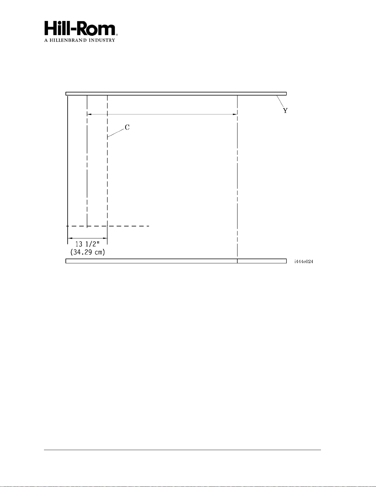
3. For the location and height of the vertical chase (C), refer to the as-built drawings (see
figure 7 on page 14).
Figure 7. Vertical Chase without Breaker Panel Layout
4. At the raceway side of the vertical chase (C), remove the corner trim (AC) from the
vertical chase (C) (see figure 8 on page 15).
5. Remove the finish cover (AD).
6. Remove the bottom cover (H), and retain the screws (AE).
7. Lift the vertical chase (C) into position on the wall (D).
8. Ensure that the top of the vertical chase (C) is flush with the ceiling (Y) (see figure 7
on page 14).
9. On the wall (D), mark all six pairs of 1" (3 cm) holes (AB) in the backplate of the ver-
tical chase (C) (see figure 8 on page 15).
10. Set the vertical chase without breaker panel (C) aside.
11. At each pair of holes (AB) marked on the wall (D), drill only one of the 1" (3 cm)
holes in the dry wall. If an obstruction or wall stud is encountered, use the alternate
marked hole.
Refer to as-built drawings
Bed centerline
Table of contents
Other Hillrom Power Tools manuals


