Sherline Products 8-DIRECTION MILL Owner's manual
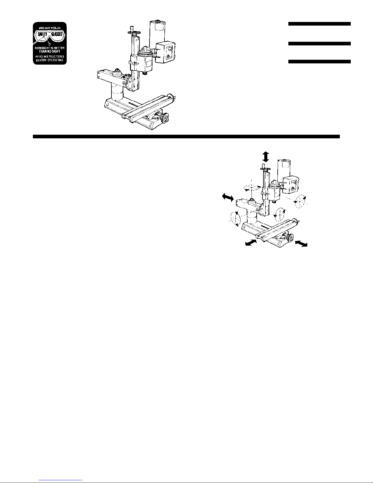
8-DIRECTION MILL
P/N 2000 (Metric P/N 2010)
Using the multidirectional milling capabilities
The design of the 8-direction mill allows you to do
everythingthatcouldbedonewithpreviousmodelsofthe
Sherline mill plus much more. Now angled holes can be
drilledormillingoperationscanbecompletedfromalmost
any angle on parts mounted square to the table. The
increased swing and movement of the column allows
larger surfaces to be machined, eliminating the need for
thehorizontalmillingconversion.
Unpacking and assembling a new 8-direction mill
The major components of your new 8-direction mill are
preassembled at the factory and are then packaged for
efficient shipping. After unpacking your shipping box,
you will then assemble the major components to ready
your mill for operation. The mill XY base must be
removedfromthe piece ofplywoodthat locates itduring
shipment. To make any adjustments to the handwheels,
backlash, gibs and so on, see the instruction manual that
isincludedwiththemill.Instructionsarealsofoundthere
for assembly of the headstock/motor/speed control unit.
Toassemblethemulti-directioncolumn,makereference
to the exploded view provided on the last page of these
instructions and complete the steps that follow:
1. Attach the round column base(P/N 5666)to the mill
base with the two 1/4-20 x 1-1/2" socket head cap
screwsprovided.
2. Screwthearmhold-downbolt(P/N5613)intothetop
oftheroundcolumnbaseandtightenwithanadjustable
wrench. Two flat indentations are provided for the
wrench to grip.
3. Sliptheroundcolumntop(P/N5655)overthepinand
rotateituntiltheflatsidesareparalleltothemillbase
withtheengravedindicatorlineonthesamesideasthe
X-axishandwheel.
4. Usingan11/16"or17mm*wrench,loosentheflange
nut holding the bed and swing arm together. Rotate
the bed away from the swing arm until they are at
approximately a 90° angle to each other. Retighten
the flange nut firmly to hold the column in this
SHERLINE
PRODUCTS
INCORPORATED 1974
SHERLINE PRODUCTS INC. ··
··
· 3235 Executive Ridge ··
··
· Vista ··
··
· California 92083-8527 ··
··
· FAX: (760) 727-7857
Toll Free Order Line: (800) 541-0735 ··
··
· International/Local/Tech. Assistance: (760) 727-5857 ··
··
· Internet: www.sherline.com
12/11/00,1of6
position. Discard the protective spacer that was
installed between the bed and arm during shipping.
*NOTE:A17mmwrenchusuallyworksonan11/16"hex
nutbutisaclosefit.Ifyour17mmwrenchistootightand
you don’t have any inch tools you will have to use an
adjustablewrench.
5. Set the swing arm over the column and align it
approximatelysquarewiththemillbaseandinabout
the center of its travel. Make sure the swing arm
registersontheflatsofthecolumntopandisproperly
seated.Whilestillholdingtheswingarmunitinplace,
setthehold-downwasher(P/N5620)overtheendof
the bolt. Put a flange nut on the end of the bolt and
tightenitagainstthehold-downwasherfirmlytolock
the swing arm in place. NOTE: There should be NO
LUBRICATION on the mating surfaces between
thearm andthe columnbase. Frictionbetween these
surfaces keeps the arm from moving during cuts.
6. Placethecolumnadjustmentblock(P/N5635)ontop
of the swing arm and attach it with two 10-32 x 5/8"
socket head cap screws at both ends. Adjust the
1"longcenterboltsothatitisjusttouchingtheflatin
the bottom of the relieved section in the top of the
FIGURE 1—The axes of movement of a Sherline 8-
direction mill.
XY
Z
4
5
6
7
8
Note: This is a supplement to the instructions included in the Sherline
Assembly and Instruction Guide that comes with each new machine.

pivotknucklewhenthecolumnisinthe90°position.
NOTE: If you remove the column adjustment block to
accommodate a backward tilt movement of the column,
makesureyoureplaceitwhenreturningthecolumntoan
upright position. It not only serves as a reference point
when returning the column to the 90° position, it also
keepsitfrom accidentally swingingdownand damaging
the table if the flange nut is loosened.
7. Slip the alignment key* into its keyway in the mill
saddle.Placetheheadstock/motor/speedcontrolunit
overthepinonthemillsaddleandoverthealignment
key.Tightenthesetscrewinthesideoftheheadstock
toholdtheentireunitinplace.Rechecktobesureyou
have tightened the flange nut on the shouldered bolt
pivotpinsecurelysothatalltheweightofthecolumn
is not resting on the column adjustment block bolt.
*NOTE: The alignment key is precision ground and will
onlyfitintothekeywaywiththegroundedgestowardthe
sides.
The mill is now ready to be positioned for use if you will
bedoingangledoperationsorreadytobesquaredupifyou
will be milling square parts. The following instructions
willexplainthestepsusedto“indicatein”theheadofthe
mill so it will be square to the table.
The additional challenges of dealing with
so many adjustments
Havingsomanyadjustablecomponentsoffersyoumany
more possibilities, but it also brings with it additional
challenges.You must make sure eachof theadjustments
is securely tightened before beginning your cut. Large
clamping surfaces are provided which offer plenty of
frictional area, so it is not necessary to overtighten the
lockingnutsandscrews.Also,asyouadjustyourmachine
closertotheextremesofitsmovement,itissuggestedthat
youtakelightercutstoreducethepossibilityofflexingor
vibration. Let common sense and experience be your
guidehere.
Obviously, the additional movements provided by an 8-
directionmillcolumnalsomeanmorewillbeinvolvedin
returningthespindletoasquarepositioninrelationtothe
table.Thisisthesameprocedurethatmustbeusedonfull
sizedmachinesthatoffersimilarmovements.Beingable
to square up a mill is one of the skills that must be
developed by any machinist. Using the laser engraved
markings and the adjustment block provided with your
Sherline mill will allow you to bring it back to a location
veryclosetosquare.Fromthereyouwillusedialindicators
to “indicate in” the head the final few thousandths of an
inch.Thefirstfewtimesyoudoitwillprobablytakesome
time. The more often you do it, the faster it will go.
Remember that alignment for small parts is less critical
thanifyour cutwillbe traversingalonger distance.How
accurately you must indicate in the head will be dictated
by the parts you will be making.
Precautions on overtightening
As with all adjustments on any machine, overtightening
can distort components or ruin the built-in accuracy of
yourmachine.Thisisparticularlytrueonsmallermachines
wherethepoweroftheoperatorismuchgreaterinrelation
tothesizeofthecomponentsthanitisonlargermachines.
It is possible to deform the T-slot, which results in a
worktable that isn’t flat. I believe that the people who
damage Sherline T-slots are the same people who break
theT-slotsonexpensivehardenedandgroundtools.You
havetodevelopa“touch”sothisdoesn’thappen.Itisvery
difficult to correctly square work up with the machine if
the table is damaged and the work is “rocking”.
MACHININGTIP:Useofatoolingplate(P/N3560)is
an inexpensive way to protect the surface of your mill
table while providing a flat, versatile clamping surface.
SQUARING UP YOUR MILL
Determining the level of accuracy you really need
Squaring up a multi-direction mill can be a chore if you
want“perfection”.Itisbesttodeterminehowaccuratethe
setupmustbebeforeyoustart.Thelargeraclosetolerance
part is the better the setup required. An error of .001"
(.025mm)perinch(25.4mm)wouldbeaverysmallerror
onapart.4"(10mm) long.However,apartthatis5"long
wouldhave an errorof .005".Thetype ofmachining that
isgoingtobe performedalsohasabearing onthequality
ofthesetup.Asanexample,adrilledholedoesn’tusually
requirethequalityofsetupthatwouldbeusedforabored
hole,(assumingtheholeisbeingboredforaccuracyrather
than for lack of a drill of the proper size). The amount of
workthatwillbedonewiththesetupshouldbeconsidered
too. If your setup is just to do one particular job you only
have to set it up close enough to do that job. If the setup
willaccommodate future operationsas well, it should be
adjusted to the tolerances of the most critical job. For
example,squaringupamillandvisetoworkonanumber
of precise parts is worth more of your attention than
settingupto drilloneclearance holeina noncriticalpart.
Limitations of the production process
Before starting you should realize that these mills are
relativelyinexpensivemachinetools.Theyhaveaccurately
milledslidesbutthesurfacesarenot ground. Toincrease
the accuracy of a Sherline tool only a percentage point
would dramatically increase the price. We try to give a
customerwhatweconsider“themostbangforthebuck”.
Why aren’t there alignment pins
to square up the machine?
If you are a novice to machining, you probably believe a
machineshouldbedesignedsothatacoupleofpinscould
be dropped into holes, squaring up the machine and
eliminating this whole process. After all, that is the way
they do it with woodworking machinery. The truth is the
tolerances that work well for wood cutting tools simply
aren’taccurateenoughformostmetalworkingtools.You
P/N 2000, 2 of 6
NOTE: Before installing the adjustment block squaring
fixture onto the swing arm, make sure there are no chips
or debris in the pocket of the arm mount or on the end of
theadjustment screw.
justcan’t hold thetolerancesrequired with“pins”.When
they fit tight enough to lock the head square to the table
youcan’tremovethemtodo work that isn’tsquare.They
become more of a problem than the problem they were
installed to eliminate. For example, an alignment or
assembly error of .010" in a wooden kitchen table will
neverbenoticed.Usuallytheflooritsitsonisnotevenflat.
It would be a waste of time and effort to make it more
accurate than it has to be. On the other hand, a cylinder
that has been bored out of square with the crankshaft in
an automobile engine could wear the entire engine at an
alarmingrate.Thepistongoesupanddownamilliontimes
in a normal day’s use. The additional cost in fuel and
shortened life demands accuracy. The Model 2000
Sherline mill allows you to provide this accuracy by
making the adjustments required to suit a particular job.
Start by getting the column close to
square with the table
Thefirst place tostart isto getthecolumn approximately
squarewiththetableusingthepointersandlaserengraved
scalesonthemachine.Thefirsttimeyousetitupyouwill
have to use a machinist’s square on the side-to-side
columnrotaryadjustmentasthepointerwillnothavebeen
"zeroed in" yet. None of these adjustments must be
extremely precise at this point because a finger type dial
indicatorwillbeusedtomakethefinal adjustments later.
Removetheheadstock/motor/speedcontrolunitfromthe
saddle.Placeamachinist’ssquareonthetableandlineup
the front of the saddle to get the column approximately
square front to back. Then line up on the right side of the
saddle to get the column approximately square side to
side. Reinstall the headstock assembly.
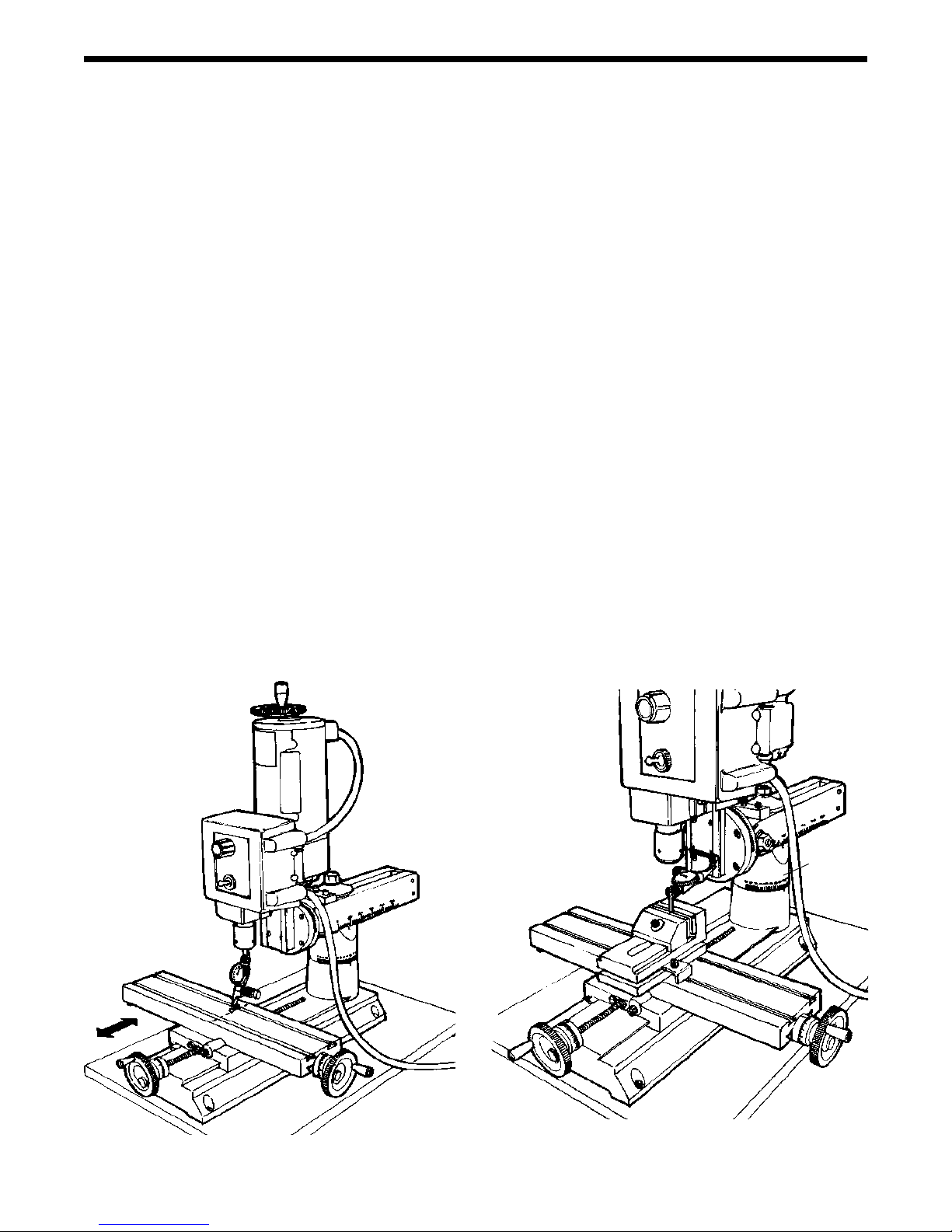
Check for any built-in error in your machine
(SeeFigure2.)Tocheckthebuilt-inerrorofthemachine
useadialindicatormountedinthespindle.Movethetable
under spindle with the Y-axis handwheel and note the
error. This error will usually be around .001" to .002"
(.05mm) in 3" (76mm). (Remember the components are
not precision ground, they are precision milled.) When
squaring the head this error should be accounted for.
Rememberyouaresquaring the headandspindleto base
of the machine where the saddle travels, not the surface
of the table itself. The head doesn’t have to be square for
thisoperationaslongasyoudon’trotatethespindlesince
you are only checking for square in one direction.
Squaring up the ram
(See Figure 3.) The next decision to make is where the
spindleis tobe located.With allthe adjustmentsthat can
bemadewiththe8-directionmillyou’llprobablystartwith
the spindle located near the middle of the X/Y table
movements. Something that isn’t too obvious should be
considered now. If the ram (the two-bar slide that allows
youtomovetheheadinoroutandleftorright)isn’tsquare
withtheX-axis,therotatingcolumncalibrationswillhave
an error. To square up the ram, mount a dial indicator to
the worktable and move the X-axis back and forth while
readingtheleft and rightsurfacesofthe column bednear
thebottom.Thisonlyhastobedoneifyouwillberotating
the column and want to be able to rely on the angle
graduationreadings.Onceset, locktheramin place with
theflangenut.WithasteelscribeorX-Acto®knifeblade,
scribealineonthecolumnbaseoppositethe“zero”mark
on the angle scale for future reference.
P/N 2000, 3 of 6
FIGURE 2—Checking for built in error in the table
travel along the Y-axis
FIGURE 3—Squaring up the ram parallel to the Y-axis.
The indicator can be held with a chuck on the table or a
mill vise as shown here.
WHEN SQUARE,
SCRIBE ZERO
REFERENCE
MARK HERE

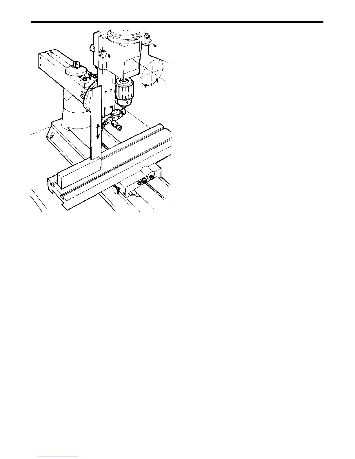
Squaring the column with the X-axis
(See Figure 4.) The column should next be squared with
theX-axis.Thisisaccomplishedwithanindicatormounted
inthespindle.Havethefoursockethead capscrewsused
to clamp the column rotation tight enough to keep the
columnfromrotating,butnotsotightthatyoucan’tmove
itwitha lighttapfrom a plasticmalletto thecolumnbed.
Becausethe axis that allows you to tiltthe columnin and
out hasn’t been squared yet you should only read the
indicatoratthesameY-axislocationontheworktablethat
you used before. Offset the indicator at an angle in the
spindle so that when the spindle is rotated it describes
about a 2" to 3" circle on the table. Take readings at the
extreme left and right positions. Adjust the column with
light taps until there is little difference in the readings at
either extreme. I wouldn’t try to get it perfect yet, just
close enough so there isn’t a gross error.
FIGURE 4—Squaring the left to right rotation of the
column with the X-axis
Squaring the column with the Y-axis
(See Figure 5.) Loosen the flange nut on the horizontal
pivot pin so that the column can be moved using the
adjustment screw in the alignment block but there is no
slop in the assembly. The tilt is harder to set because the
spindle doesn’t rotate at the pivot point, but once you
understandthis,thetaskbecomessimpler.Thealignment
block adjustment screw helps make fine adjustments in
thisdirectioneasy.Withtheblockinplaceandtheflange
nutloosetheentireassemblyiskeptfromfallingforward
by the adjusting screw. This block can be left in place
unless the ram is completely retracted or the column is
tiltedbackatananglethatinterfereswiththeblock.With
theindicatorstillheldinthespindle,takereadingsparallel
with the Y-axis near the front and rear edges of the table.
Raise or lower the column with the alignment block
adjusting screw until the readings are the same front and
rear.Remember the location of thepivot pointand allow
for it.
Example:
If the indicator reading is larger at the front of the table
than the back, then that means the column must be tilted
back. Say your reading is “0” at the back and .010"
(.25mm) at the front. If you tipped the column back until
theindicatorreadzeroatthefront,thereadingattheback
would not remain at “0” but would now be a negative
reading.This iscaused because the pivot point is located
far enough behind the spindle so that both front and rear
measuring points are still in front of it. Swinging the
column back actually raises both points. The front point
raises more than the back point, but both do go up. You
will have to keep tilting the column back and measuring
until you get the same reading front and back. This may
requiremoremovementthatyoufirstthoughtbasedonthe
differencebetweentheinitialmeasurements.
Fine tuning the headstock alignment
(See Figure 6.) It is time to make the final adjustments to
therotatingcolumn,butfirstI’lladdalittlemoreconfusion
toyourlife.RememberwhenIsaidthatalignmentpinsare
somewhatuselesstolineupamachine?Well,asmuchas
I hate to admit it, in a sense we already have one. It is the
alignmentkeythatholdstheheadstockassemblysquareto
thecolumnsaddle,which ismountedonthe column bed.
Removal of this key is what allows you to pivot the
headstockontheSherlinelathesandmills.Itisoneofthe
featuresthatmakeourmachineseasytouse,versatileand
very adaptable. It is also another thing you have to
consider when searching for “perfect” alignment. If you
havemorethan onekey,don’t mixthemup because they
arematchedduringassemblytofitascloselyaspossible.
I have found the best way to deal with this potential
P/N 2000, 4 of 6
ADJUST FORE/AFT MOVEMENT
WITH CENTER ADJUSTMENT
SCREW ON ALIGNMENT BLOCK
LOCK ADJUSTMENT
IN PLACE WITH
11/16" FLANGE NUT
FIGURE5—Squaringtheforeandaftpivotmovementof
the column with the Y-axis
P/N 2000, 5 of 6
problemistopushtheheadsquareagainstthekeybefore
tighteningtheconepointscrewthatlockstheheadstockin
place.Ifyoueverwanttocheckalignmentofthekeytothe
column bed, mount a dial indicator in the spindle. Raise
and lower the head while reading the vertical edge of a
precisionsquare.Adjusttherotatingcolumnuntilthereis
no error as the indicator moves up and down the square.
Now read the table with the indicator. If the slot and key
areperfectthereshouldn’tbeanyerror,butin mostcases
therewillbeasmallamount.Thiscanusuallybeeliminated
by taking advantage of what play does exist in the
alignment key and slot. With the cone point set screw
loosened slightly, tap the headstock with a plastic mallet
to take out play in the direction you want to go. Then
retighten the set screw.
Making final adjustments
Therotatingcolumnandtiltingadjustmentscanbefinalized
so the indicator reads “0” as the spindle is rotated,
however the error we measured when checking the table
flatness could be accounted for now if need be. If the
pointeron the backof therotary column diskdoesn't line
upwiththezeromark,loosenthescrewholdingitinplace
and reset it to indicate zero for future reference.
Yourmachine isnow “indicatedin” andready touse. As
you get a feel for your machine and go through this
adjustmentprocedurea fewtimes,the timeittakes to get
good results will decrease. Being able to accurately
indicateinamillisoneoftheskillsthatmustbedeveloped
by any machinist who plans on making accurate parts.
FIGURE6—Finetuningtheheadstockrotationalignment
with a machinist’s square and dial indicator
Thoughtheadjustmentsonlargermachinesmaybemade
in slightly different ways, the skills and procedures you
learn here can be applied to other machines as well.
Using the column spacer block
In normal use the column spacer block will not be
required.However, ifyou are working on alarger partor
yoursetup requires moreclearance undertheswing arm,
the spacer block can be installed to raise the column an
additionaltwoinches.(Installationwillbe made easierif
you first remove the headstock/motor unit to reduce the
weightofthecolumn.)Toinstallthespacerblock,remove
theflangenutontopofthecolumnhold-downbolt,andlift
off the hold-down washer so that the entire column top
andswingarmassemblycanbeliftedoffofthehold-down
bolt.Screwtheextensionboltonto the endofthecolumn
bolt and tighten with an adjustable wrench. Slide the
column spacer over the bolt and reinstall the column top
and swing arm assembly. Reinstall the headstock/motor
unit.
Lowering the headstock for working close to the table
Toworkdownclosetothetableonthinstockortorunan
end mill past the edge of the table, the column may be
loweredby placingthe columntop (P/N 5655) above the
swing arm instead of below it. Remove the flange nut,
hold-down washer and swing arm. Place the swing arm
overthehold-downboltdirectlyontopofthecolumnbase
(P/N 5666). Place the column top back onto the hold-
downboltupsidedownandreplacethehold-downwasher
and flange nut. Although you cannot use the alignment
lines to help square up the head, this makes for a very
strong and stable setup.
Engineering compromises
I’malwaysat odds withmyselfwhenI writeinstructions
on complicated procedures. By giving you this much
informationIknowthatImaybesolvingaproblemforone
customer by making them aware of it. At the same time I
am probably confusing another customer who would
never have noticed the problem because of the type of
work that the mill or lathe is being used for. I don’t want
to create a customer who spends all his time trying to
achieveperfectalignment for workthatdoesn'trequire it
and ends up never using the machine. Engineering is
alwaysacompromise.Idealwiththis fact with eachnew
productthatIdesign.Whileourmachinesaren’taccurate
enoughforsomecustomers,theyarestilltooexpensivefor
others. I hope you are pleased with the new capabilities
thismulti-directionmillcanbringtoyourshop.Ithinkyou
willfindthecombinationof features offersagoodvalue.
Joe Martin, President and Owner
Sherline Products Inc.
HEADSTOCK PIVOTS ON
SADDLE PIN. EVEN WITH
ALIGNMENTKEYINPLACE,
SLIGHT ADJUSTMENT CAN
BE MADE TO GET
HEADSTOCK PERFECTLY
SQUARE..
NOTE: This instruction sheet is a supplement to the
SherlineAssemblyandInstructionGuidethatcomeswith
eachnewmachine.Forsafetyrules,operatinginstructions
and information on the other components of the Model
2000 mill, consult that publication. It also includes basic
instructionsonmetalworkingthatwillbehelpfulfornew
machinists.
P/N 2000, 6 of 6
1
3
10
72
6
26
4
5
9
11
11 12
13
14
15
16
20
21
8
22
25
18
19
17
23
24
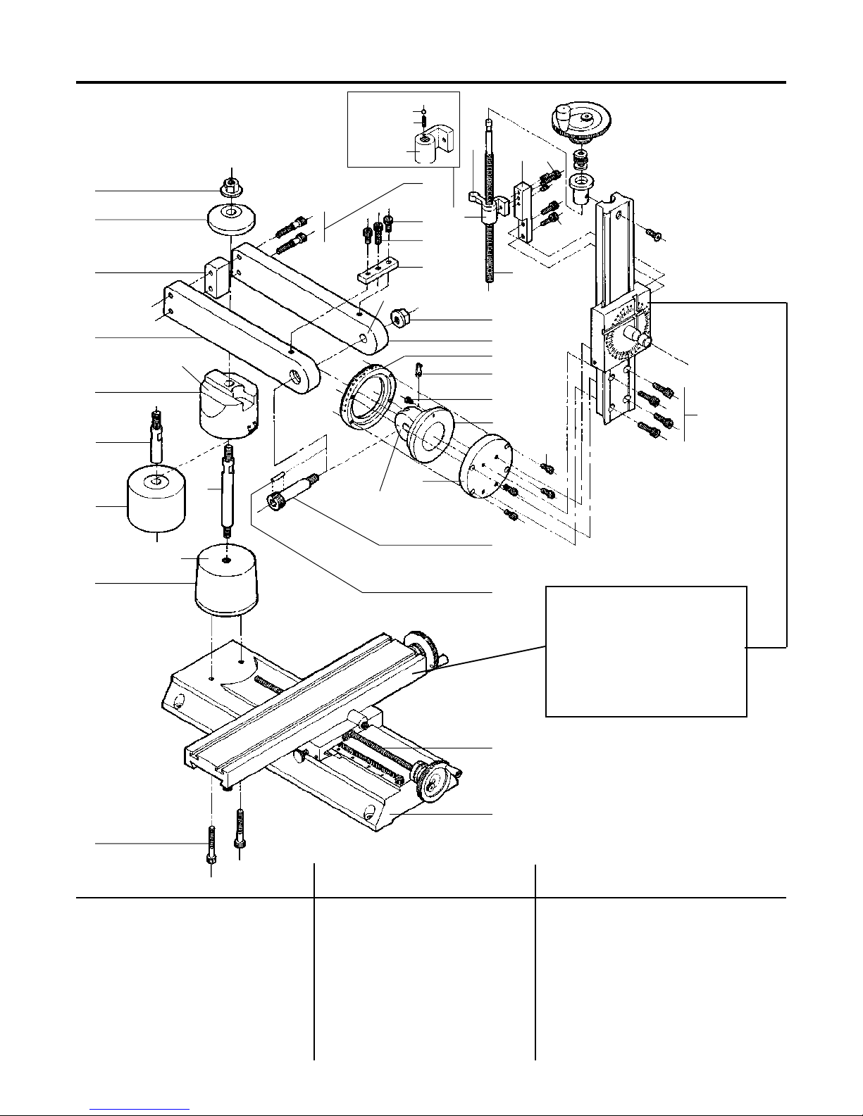
NOTE
For part numbers of table, column bed,
saddle and headstock/motor/speed
control portions of mill, see exploded
view in the Sherline Assembly and
Instruction Guide that came with your
mill.
EXPLODED VIEW AND
PARTS LISTING
SHERLINE MODEL 2000 MILL COLUMN
27
28 29 25
26
REF NO.
NO. P/N REQ. DESCRIPTION
1 35160 1 Graduated Clamping Ring
2 35170 1 Moveable Clamping Disk
3 40340 1 10-32 x 1" SHCS
4 40330 2 10-32 x 5/8" SHCS
5 56240 2 1/4-20 x 1-1/2" SHCS
6 56010 1 #2000 Mill Base (Metric P/N 5602)
7 56130 1 Arm Hold-down Bolt #2000
8 56200 1 Arm Hold-down Washer #2000
9 56210 1 3/8-16 x 2" Shouldered Bolt
10 56220 1 Swing Arm side #2000
REF NO.
NO. P/N REQ. DESCRIPTION
11 56230 2 Flange Nut
12 50220 2 1/4-20 x 1-3/4" SHCS
13 56330 1 Swing Arm side #2000
14 56350 1 Column Adjustment Block
15 56400 1 Arm Spacer Block #2000
16 56440 1 Arm Mount #2000
17 56450 1 Index Tab
18 50211 1 8-32 x 1/4” Button Head Screw
19 56470 1 3/32” x 1/2” Dowel Pin
20 56550 1 Model 2000 Column Top
REF NO.
NO. P/N REQ. DESCRIPTION
21 56700 1 Model 2000 Column Base
22 56160 1 Y-axis leadscrew (Metric P/N 5615)
23 56110 1 Extension bolt
24 56770 1 Column spacer
25 40690 5 10-32 x 3/4” SHCS
26 40670 6 10-32 x 1/2” SHCS
27 40177 1 Saddle nut w/ ball (Metric P/N 41177)
28 40175 1 Saddle locking lever (Metric P/N 41175)
29 40176 1 Saddle travel extension
30 45011 1 Z-axis leadscrew (Metric P/N 45161)
30
SADDLE NUT DETAIL
SADDLE NUT
(Asby.–40177/41177)
SPRING, P/N 22630
1/8" BALL, P/N 40178
NO LUBRICATION HERE
NO LUBRICATION HERE
NO LUBRICATION HERE
NO LUBRICATION HERE
Table of contents
Other Sherline Products Power Tools manuals


Popular Power Tools manuals by other brands


Huskie Tools
Huskie Tools SL-750 Operation manual

Gesipa
Gesipa taurus 1 Operating manual with spare parts list

Parkside
Parkside PBSG 95 C3 Translation of the original instructions

Metabo
Metabo STEB 70 Quick Original instructions

Skil
Skil 4570 Operating/safety instructions

EINHELL
EINHELL BT-HA 2000 operating instructions


