ABB B-CK 240 User manual

Power and Productivity
for a better world™
Operating Instructions
HYDRAULIC COMPRESSION TOOL SET
Catalog Number: B-CK 240
TA04902 C Page 1 of 8
Page
1.0 GENERAL INFORMATION..................... 2
1.1 Warnings & Safety Rules ...................... 2
1.2 Features............................................... 2
1.3 Specifications....................................... 2
2.0 Parts & Accessories .............................. 3
2.1 Hydraulic Compression Tool ................. 3
2.2 Battery Charger.................................... 3
2.3 Battery ................................................. 3
2.4 Carrying Case ...................................... 3
2.5 Optional Power Supply......................... 3
3.0 Operating Instructions .......................... 4
3.1 Charging the Battery............................. 4
3.2
Attaching & Detaching the Battery Pack
. .. 4
3.3 Switch Operations................................ 4
3.4 Compression Operation ....................... 5
3.5 Maintenance & Inspection .................... 5
3.6 Troubleshooting.................................... 6
4.0 Important Operation Precautions ........ 6
4.1 Precautions for the Compression Tool .. 6
4.2 Precautions for the Battery Pack. ......... 6
4.3 Precautions for the Charger. ................. 6
5.0 Parts Breakdown................................... 7
5.1 Parts Diagram ...................................... 7
5.2 Parts List.............................................. 8
TABLE OF CONTENTS

IMPORTANT: Read and understand all of the
instructions and safety information in this manual
before operating or servicing this tool.
1.0 GENERAL INFORMATION
ABB conrms the tool described in this instruction manual complies with the basic safety and health requirements of
EC Machinery Directive 2006/42/EC and EMC Directive 2004/108/EC relating to electromagnetic compatibility.
WARNINGS & SAFETY RULES
1.1
WARNINGS
1. BE FAMILIAR WITH YOUR TOOL.
Read the instruction manual. Become aware of its proper
usage as well as the potential hazards.
2. NEVER ATTEMPT TO MAKE A COMPRESSION ON A
"HOT" LINE. HIGH VOLTAGE!
• Never assume the power is OFF! Determine beforehand
if any electrical hazards could exist when making a
connection to a line or wire.
• Tools are NOT insulated for use on or near energized
conductors. Use of these tools near energized
conductors may lead to electrical shock, causing severe
injury or death. DO NOT use these tools near energized
conductors without adequately insulating operator and
surroundings.
3. KEEP FINGERS AND OTHER BODY PARTS AWAY
FROM COMPRESSION DIES & MOVING PARTS.
Pinch point hazard. Compression Dies at high force can
cause severe personal injury. Keep all body parts away
from moving parts of the tool during operation.
4. DO NOT SHORT CIRCUIT THE BATTERY.
5. WEAR ALL REQUIRED PERSONAL PROTECTIVE
EQUIPMENT.
6. DO NOT DISPOSE OF TOOL OR BATTERY AS
RESIDUAL WASTE. RECYCLE EXHAUSTED
BATTERIES. TOOL CONTAINS HYDRAULIC OIL,
CIRCUIT BOARDS, AND OTHER COMPONENTS
WHICH MUST BE DISPOSED OF SEPARATELY
ACCORDING TO LOCAL ENVIRONMENTAL
STANDARDS.
SAFETY RULES
1. KEEP WORK AREA CLEAN AND WELL LIGHTED.
Poor lighting and cluttered areas invite accidents.
2. MAINTAIN TOOL WITH CARE. Keep tool in good
condition at all times. Keep it clean for best and safest
performance.
3. DON'T OVER-REACH. Keep proper footing and balance
at all times.
4. NEVER OPERATED TOOL WITHOUT CRIMPING DIES
INSTALLED. Ensure connector material is inserted
between dies before compression.
FEATURES1.2
• Fully automatic, self-contained power tool.
• Removable battery cartridge - simply change the
cartridge for continuous use.
• One handed operation.
• Fully enclosed weather resistant housing.
• LED work lights.
IN ORDER TO OBTAIN WARRANTY SERVICE YOU
MUST REGISTER YOUR PRODUCT BY LOGGING
IN ON www.tnb.com/toolregistration. FAILURE TO
REGISTER YOUR PRODUCT VOIDS ALL
WARRANTIES.
SPECIFICATIONS
HYDRAULIC COMPRESSION TOOL:
B-CK240
Drive Unit: 1
4.4V DC Motor
Dimensions:
425 mm L x 89 mm W x 144 mm H
Weight:
2.6 kg without battery
Capacities:
6-240 mm
2
Jaw Opening:
45 mm
Output:
52 kN
BATTERY:
BAT-LI34
Battery Type: Sealed Lithium Ion
Voltage:
14.4V DC
Dimensions:
110 mm L x 70 mm W x 130 mm H
Capacities:
3.3 Ah
Weight:
0.56 kg
Charging time:
60 minutes
CHARGER:
BATC-230
Input Voltage: 230 V, 50 Hz
Dimensions:
150 mm L x 90 mm W x 85 mm H
Weight:
0.5 Kg
1.3
TA04902 C Page 2 of 8
41 2 3
65 5 5

HYDRAULIC COMPRESSION TOOL (B-CK 240)
2.1
Ram
LED
Work Light
LED
Work Light
Work Light
Button
Hanging Strap
Advance
Trigger
Release
Button
CHARGER
(
BATC-230
)
2.2
LED Lamp
Air Vent
Air Vent
Air Vent
CARRYING CASE
2.4
BATTERY
(
BAT-LI34
)
2.3
OPTIONAL POWER SUPPLY (POWER-230)
SOLD SEPARATELY
2.5
2.0 PARTS AND ACCESSORIES
TA04902 C Page 3 of 8

100%
Stop
100%
Stop
GREENRED
RED
CHARGING THE BATTERY
3.1
Left
LED Lamp
Battery
Right
LED Lamp
1. Connect the power cord of Charger BATC-230 to a 230V 50Hz outlet. The Left LED Lamp Illuminates Red [STAND BY].
2. Insert the Battery rmly into the charger.
The Right LED Lamp Illuminates Green [CHARGING].
NOTE: Do not short-circuit the Charger by placing foreign materials in the contacts on Charger, as this will damage the Charger
and expose the user to potential safety hazards.
3. Charging takes approximately 60 minutes (100% capacity).
When charging is complete, the Right LED Lamp Blinks GREEN [COMPLETION].
NOTE: Alternate LED Lamp displays as shown:
Left LED:
Indicates Operating Mode
RED shines: Charger in operation
RED blinks: Charging error
(Malfunction)
Right LED:
Indicates Operating Mode:
GREEN shines: Battery is recharging
GREEN blinks: Battery is fully charged
RED shines: Battery is fully defective
RED blinks: Charging error
(battery is overheated / cold)
Leave the battery in the charging slot until the correct
temperature has been reached and charging is possible.
IMPORTANT INFORMATION! (see Step 4.3)
The lithium ion battery pack LiA-34 will be
automatically calibrated for optimized charging
operation:
Left LED:
Indicates Operating Mode:
RED shines: Charger in operation
Right LED:
Indicates Operating Mode:
GREEN shines, RED blinks four times additionally.
Charging starts after calibration as described above.
ATTACHING & DETACHING THE BATTERY PACK
3.2
1. To attach the Battery, slide
it into the base of the Tool
until it stops and the Latch
engages.
2. After inserting the Battery,
check that it is securely in
place by pulling it gently
without pressing the Latch.
3. To detach the Battery, pull
out the Battery while
pressing the Latch.
Bottom
of Tool
Battery
Press Latch
for Detaching
Insert
Detach
3.0 OPERATING INSTRUCTIONS
SWITCH OPERATIONS
3.3
1. The ram advances when the Trigger is depressed and
stops when the Trigger is released.
2. To retract the ram, depress the Release Button. The ram
continues to retract while the Release Button is depressed.
Trigger
Release
Button
Work Light
Button
TA04902 C Page 4 of 8

MAINTENANCE & INSPECTION
3.5
1. To ensure smooth operation and prevent rust, store the tool in a cool dry area. Ensure that moving parts are lubricated regularly.
2. When the plastic housing becomes dirty, clean it with a soft soaped cloth.
3. Dust, sand, and dirt impact the operation, performance and durability of any hydraulic device. After each use, the tool should be
wiped with a clean cloth taking care to remove any residue, especially close to the movable parts.
NOTE: Always remove the battery pack from the unit before replacing parts or maintenance.
FIGURE 1
Lift Latch
FIGURE 2
Die Retaining Screw
Die Retaining
Screw
C-Head Ram
2
1
6 Ton Series Dies
To close, lift the C-Head
until it is securely engages
to the Latch.
FIGURE 3
Latch Engaged
COMPRESSION OPERATION
3.4
WARNING
Pinch point hazard. Compression Dies at high
force can cause severe personal injury. Keep
all body parts away from moving parts of the
tool during operation.
1. Retract the Ram fully by pressing the release button (see Step 3.3).
2. Open the tool head by lifting the Latch (Figure 1).
3.
Select the appropriate size dies for the connector being used.
4. Loosen the two Die Retaining Screws. Insert one die half into the C-head
and then insert the other half of the die into the Ram (Figure 2). Tighten the Die Retaining Screws.
5. Close by lifting the C-Head until it is securely engaged to the Latch (Figure 3).
6. Place connector between the dies. Press the trigger and advance the Ram (Step 3.3) so the connector is held lightly
between the dies. Do not deform the connector.
7. Insert the conductor into the connector.
8. Press the trigger until the compression is complete. A series of clicks will be heard followed by a release in the pressure
when compression is complete.
9. Press the release button (Step 3.3) to retract the ram. The ram continues to retract while the release button is pressed.
The ram stops when it is fully retracted.
10. Remove the compressed connector from the tool.
TA04902 C Page 5 of 8

4.0 IMPORTANT OPERATING PRECAUTIONS
TROUBLESHOOTING
3.6
Problem Cause Solution
The motor does not operate at all.
The battery is not charged or defective. Charge or replace the battery.
There is dust or foreign objects lodged at
the battery contacts. Remove foreign objects.
The switch is misaligned. Check to see if switch is aligned with trigger,
consult tool service.
The motor runs but ram will not advance, or ram
advances but will not build pressure.
Consult tool service.
Air in hydraulic system.
Insufcient hydraulic oil.
Hold the tool with head towards the oor to
allow air to rise towards top of oil bladder.
Defective hydraulic circuit. Consult tool service.
The ram will not retract
Tool did not complete a full cycle and
bypass.
Depress trigger and allow tool to reach full
pressure and bypass, then depress release
button to retract the ram.
The connector is jammed in compression
dies.
Depress and hold release button while prying
compression dies apart.
The release button is bent or misaligned. Consult tool service.
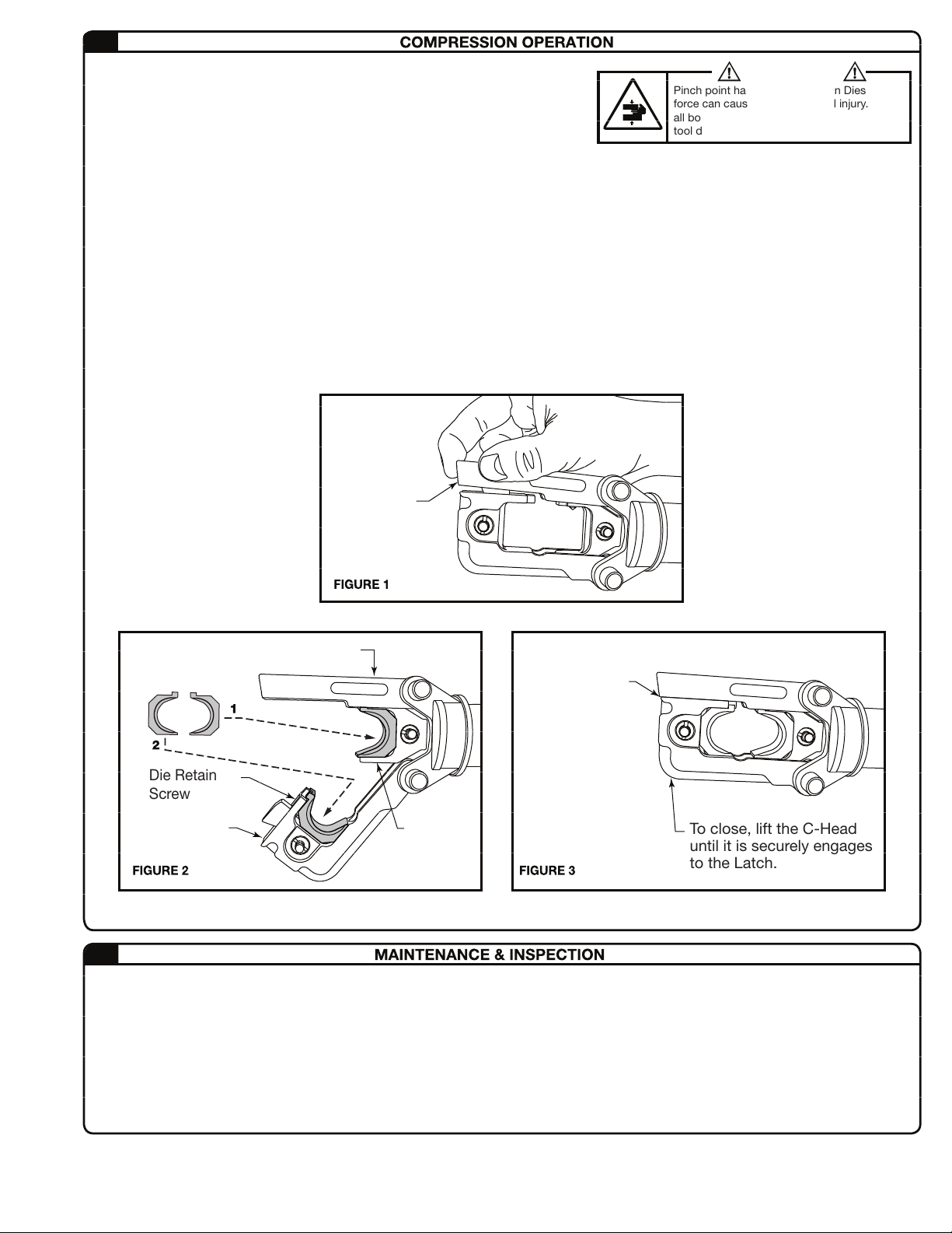
4.1 PRECAUTIONS FOR COMPRESSION TOOL
1. Select the appropriate dies for the connector and
conductor to be compressed. Incorrect combinations
result in inferior connections between the connector and
conductor and are an electrical hazard.
2. Never operate the tool without dies installed.
3. Always point the tool away from other people.
4. If the tool is stored for an extended period at a
temperature of less than 25º F (-5º C), the tool should be
allowed to return to room temperature to ensure smooth
operation. Use the tool only after it has been at room
temperature for 1 hour.
5. Do not drop the tool. Dropping the tool may damage the
hydraulic circuit and cause malfunctions.
6.
Keep the head and ram clean and free of debris. Solvents
can be used to clean the head but should not be used on
the plastic body. Use soap & water to clean the body.
PRECAUTIONS FOR THE BATTERY PACK
4.2
1. Do not short circuit the contacts or expose the
battery to water, oil or solvents.
2. Do not disassemble or attempt to repair the
battery.
3. Do not dispose of the battery by burning or as residual waste.
4. Do not drop or otherwise abuse the battery.
5. Do not leave the battery in locations where it will be
exposed to a temperature greater than 104 degrees F (40
degrees C) for an extended period.
6. The battery has a limited life. When the charge holding
capacity becomes about 1/2 that of the original capacity,
the battery should be replaced.
7. If the battery is stored without being charged, natural
drainage will cause the power to be reduced. The battery
should be charged every 3 months if not in use regularly.
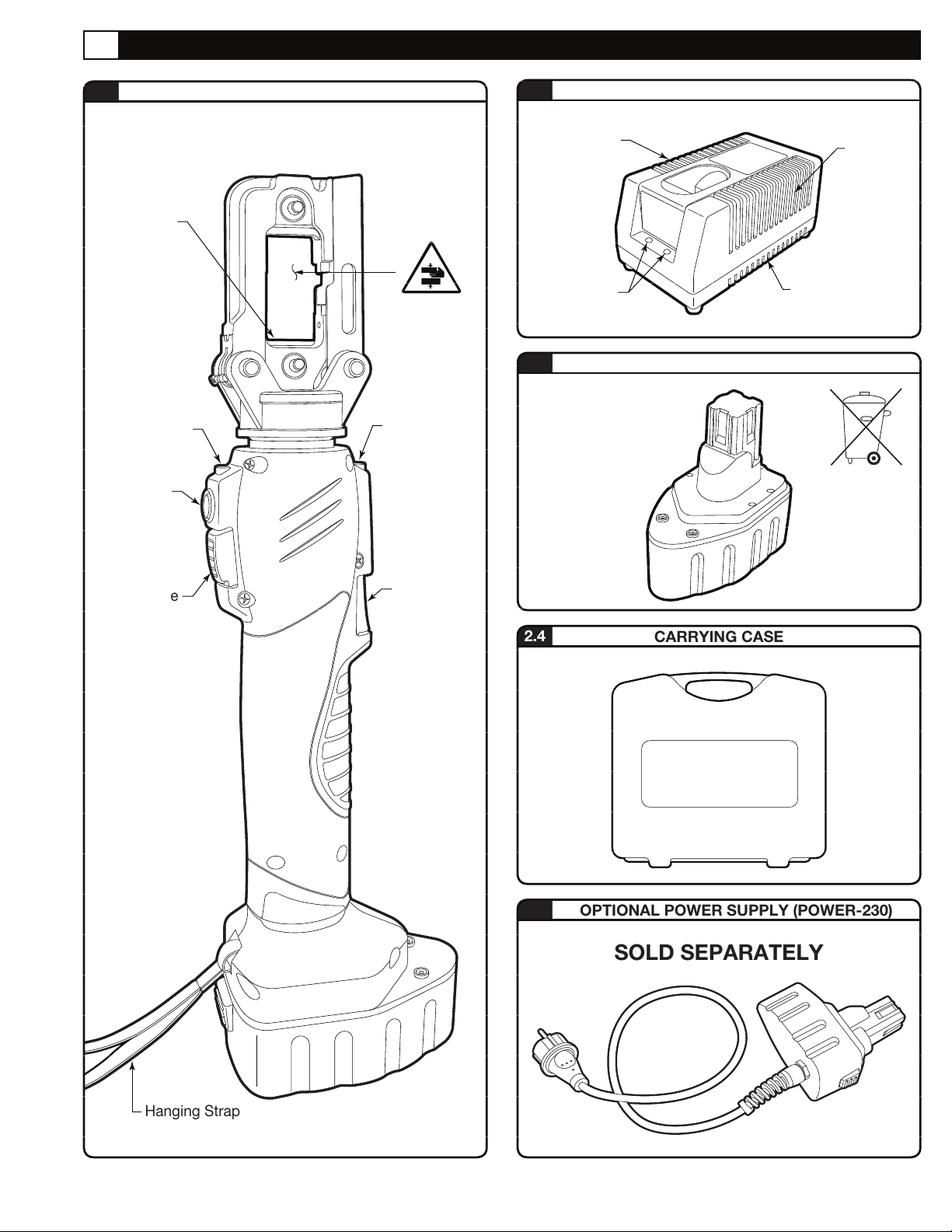
PRECAUTIONS FOR THE CHARGER
4.3
1. The Right LED lamp illuminates green and remains on when the unit begins charging a battery. The indicator Blinks Green
when charging is completed.
2. This unit is for charging battery BAT-LI 34 only. Do not use the charger for any other devices.
3. The Charger automatically calibrates the battery as needed for optimized charging. The Right LED lamp will Illuminate Green
then Blink Red 4 times to indicate calibration. Charging will begin after calibration completes.
4. Charge batteries at an ambient temperature of 50-95 degrees F (10-35 degrees C). Charging time is approximately 60
minutes for 100% capacity. If the Right LED Blinks RED, the battery is too HOT/COLD. Leave the battery in the charging slot
and charging will begin once the proper temperature is reached.
5. Never short circuit the output contacts.
6. Do not expose the charger to water, oil or solvents.
7. Do not disassemble, modify, drop or otherwise abuse the charger.
TA04902 C Page 6 of 8

B-CK240 PARTS DIAGRAM
5.1
5.0 PARTS BREAKDOWN
TA04902 C Page 7 of 8

TA04902 C Page 8 of 8
B-CK240 PARTS LIST
5.2
For Parts or Service, contact Thomas & Betts Tool Service Center at 1-800-284-TOOL (8665)
* not included (accessory)
Thomas & Betts Corporation
Memphis, Tennessee
www.tnb.com
ABB
8 Bvd Millenium,
B-7110 La Louviere,
Belgium
© 2016 ABB. All Rights Reserved.
NO. DESCRIPTION ITEM No. QTY NO. DESCRIPTION ITEM No. QTY
1 Housing (L) 07175017 1 49 Screw 07452020 1
2 Housing (R) 07175018 1 50 Spring 07398002 1
3 Switch Unit 07746005
07413001
1 51 Cylinder Head 07652002 1
4 Switch Rod 1
5 Switch 07746006 1
6 Spring 07123660 1
7 Release Lever 07053003 1
8 Holder 07212002 2
9 Spring 07123006 1
10 Rubber Cover 07206001 1
11 Plate 07722205 1
12 Screw 07452573 8
13 Spring Washer 07131223
07417415
8
14 Washer 8
15 Power Unit 07037001
07358012
1
16 O-Ring 1
17 Plug 07530001 1
18 Oil Reservoir 07351006 1
19 O-Ring 07358013 1
20 Bush 07068346 1
21 Spring 07123662 2
22 Seal Packing 07081344 2
23 Back-Up Ring 07358240 2
24 Valve Cap 07593226 2
25 Piston 07371224 2
26 Steel Ball 07506101 1
27 Screw 07452254 1
28 Retainer 07044001 1
29 Scew 07452019 1
30 Spring 07123663 2
31 Ball 07277123 3
32 O-Ring 07358698 2
33 Valve 07559293 2
34 Filter 07136002 2
35 Ring 07386322 2
36 Spring 07123664 1
37 O-Ring 07358186 2
38 Back-Up Ring 07535152 1
39 Plug 07530250 1
40 Reaction Pin 07055206 1
41 O-Ring 07358242 1
42 Housing 07175019 1
43 Valve Screw 07585217 2
44 Spring 07123665 2
45 Ball 07277122 2
46 O-Ring 07358014 1
47 Back-Up Ring 07535153 1
48
Piston
07267018 1
52 Screw 07452789 2
53 Plug 07040001 1
54 Spring 07123219 1
55 Screw 07452243 1
56 Retaining Screw 07606001 4
57 Pin 07105002 4
58 Holder 07212003 1
59 Bush 07157001 2
60 Spring 07123007 2
61 Screw 07452023 1
62* Crimping Die Accessory 2
63 Spring 07123008 1
64 Screw 07452021 2
65 Hanger 07069002 1
66 Hanger 07452022 1
67 Lock 07452022
68 Spring 07123009
1
1
70 Relief Valve 07546007 1
Table of contents
Other ABB Power Tools manuals

ABB
ABB REX 521 User manual

ABB
ABB Smart Tool + User manual

ABB
ABB VD4G-25 User manual

ABB
ABB VD4 Series User manual

ABB
ABB AMVAC Quick start guide

ABB
ABB Emax E1 Quick guide

ABB
ABB AMVAC Quick start guide

ABB
ABB GSec/T1 Programming manual

ABB
ABB HD4 Series Quick guide

ABB
ABB Thomas&Betts BAT22-6NV2 User manual